KnxEib
by Luis A Alvarez-Gomez
switch1
light
with
| ETS Basics |
Structure | Setup ETS5 |
Working with ETS5 |
|---|---|---|---|
|
Device Swithes Actuators PhyAddr GroupAddr On/Off Feedback SimPanel MinSetup |
Bus Line Area PhyAddr |
Buildings Catalogs GroupAddr |
Switches
System (Plant) Inputs
Actuators
System (Plant) Outputs

Knx
device
1.1.3
Channel 1
Channel 2
Channel 3
Channel 4
Switches
Actuators
Bus
Knx


Knx
device
1.1.2
Channel 1
Channel 2
Channel 3
Channel 4
Knx
device
1.1.1
Channel 1
Channel 2
Channel 3
Channel 4
Knx
device
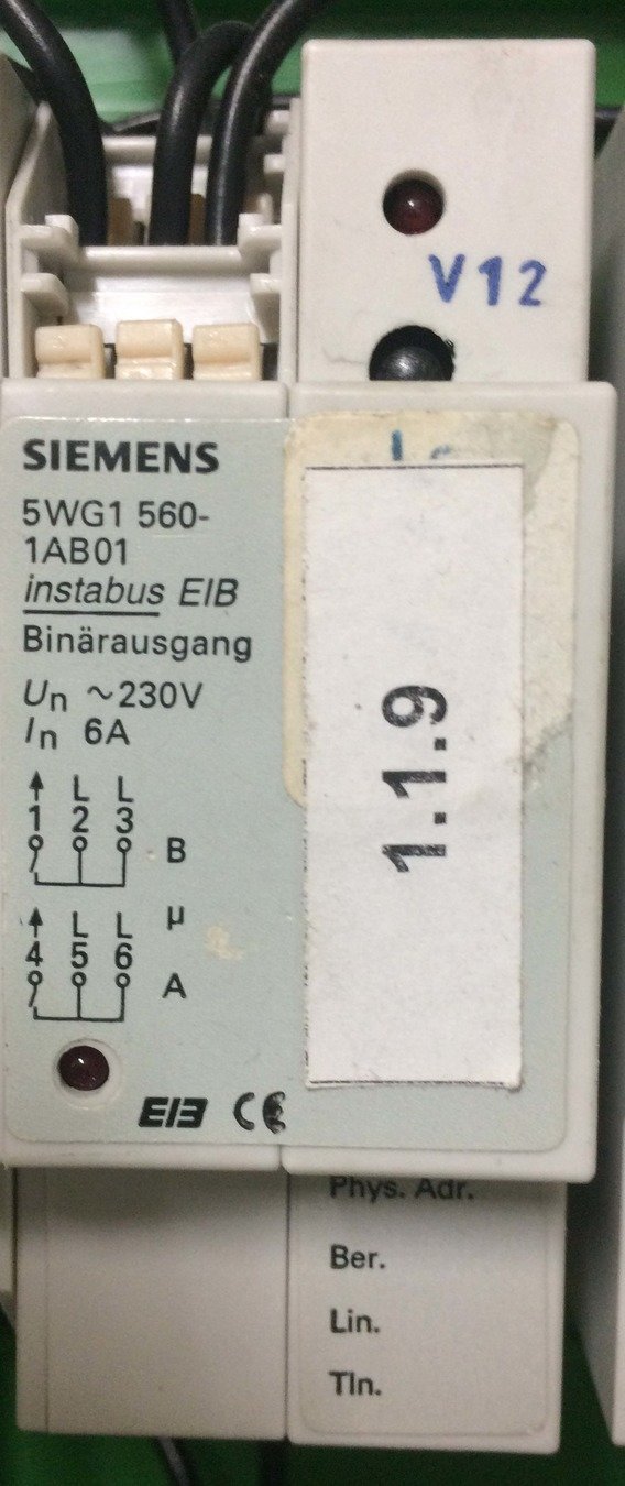
1.1.9
Channel 1
Channel 2
Channel 3
Channel 4
Knx
device
2.2.1
Channel 1
Channel 2
Channel 3
Channel 4
Knx
device
2.1.2
Channel 1
Channel 2
Channel 3
Channel 4
Knx
device
1.1.3
Channel 1
Channel 2
Channel 3
Channel 4
Switches
Actuators
Bus
Knx
Knx
device
1.1.2
Channel 1
Channel 2
Channel 3
Channel 4
Knx
device
1.1.1
Channel 1
Channel 2
Channel 3
Channel 4
Knx
device
1.1.9
Channel 1
Channel 2
Channel 3
Channel 4
Knx
device
2.2.1
Channel 1
Channel 2
Channel 3
Channel 4
Knx
device
2.1.2
Channel 1
Channel 2
Channel 3
Channel 4
Group Addresses
1/1/1
1/1/1
1/1/1
1/1/2
1/2/3
1/2/2
Knx
device
1.1.3
Channel 1
Channel 2
Channel 3
Channel 4
Switches
Actuators
Bus
Knx
Knx
device
1.1.2
Channel 1
Channel 2
Channel 3
Channel 4
Knx
device
1.1.1
Channel 1
Channel 2
Channel 3
Channel 4
Knx
device
1.1.9
Channel 1
Channel 2
Channel 3
Channel 4
Knx
device
2.2.1
Channel 1
Channel 2
Channel 3
Channel 4
Knx
device
2.1.2
Channel 1
Channel 2
Channel 3
Channel 4
Group Addresses
1/1/1
1/1/1
1/1/1
1/1/2
1/2/3
1/2/2
"On"
Knx
device
1.1.3
Channel 1
Channel 2
Channel 3
Channel 4
Switches
Actuators
Bus
Knx
Knx
device
1.1.2
Channel 1
Channel 2
Channel 3
Channel 4
Knx
device
1.1.1
Channel 1
Channel 2
Channel 3
Channel 4
Knx
device
1.1.9
Channel 1
Channel 2
Channel 3
Channel 4
Knx
device
2.2.1
Channel 1
Channel 2
Channel 3
Channel 4
Knx
device
2.1.2
Channel 1
Channel 2
Channel 3
Channel 4
Group Addresses
1/1/1
1/1/1
1/1/1
1/1/2
1/2/3
1/2/2

Knx
device
1.1.3
Channel 1
Channel 2
Channel 3
Channel 4
Switches
Actuators
Bus
Knx
Knx
device
1.1.2
Channel 1
Channel 2
Channel 3
Channel 4
Knx
device
1.1.1
Channel 1
Channel 2
Channel 3
Channel 4
Knx
device
1.1.9
Channel 1
Channel 2
Channel 3
Channel 4
Knx
device
2.2.1
Channel 1
Channel 2
Channel 3
Channel 4
Knx
device
2.1.2
Channel 1
Channel 2
Channel 3
Channel 4
Group Addresses
1/1/1
1/1/1
1/1/1
1/1/2
1/2/3
1/2/2
feedback
Knx
device
1.1.3
Channel 1
Channel 2
Channel 3
Channel 4
Switches
Actuators
Bus
Knx
Knx
device
1.1.2
Channel 1
Channel 2
Channel 3
Channel 4
Knx
device
1.1.1
Channel 1
Channel 2
Channel 3
Channel 4
Knx
device
1.1.9
Channel 1
Channel 2
Channel 3
Channel 4
Knx
device
2.2.1
Channel 1
Channel 2
Channel 3
Channel 4
Knx
device
2.1.2
Channel 1
Channel 2
Channel 3
Channel 4
Group Addresses
1/1/1
1/1/1
1/1/1
1/1/2
1/2/3
1/2/2
"Off"
Knx
device
1.1.3
Channel 1
Channel 2
Channel 3
Channel 4
Switches
Actuators
Bus
Knx
Knx
device
1.1.2
Channel 1
Channel 2
Channel 3
Channel 4
Knx
device
1.1.1
Channel 1
Channel 2
Channel 3
Channel 4
Knx
device
1.1.9
Channel 1
Channel 2
Channel 3
Channel 4
Knx
device
2.2.1
Channel 1
Channel 2
Channel 3
Channel 4
Knx
device
2.1.2
Channel 1
Channel 2
Channel 3
Channel 4
Group Addresses
1/1/1
1/1/1
1/1/1
1/1/2
1/2/3
1/2/2
Knx
device
1.1.3
Channel 1
Channel 2
Channel 3
Channel 4
Switches
Actuators
Bus
Knx
Knx
device
1.1.2
Channel 1
Channel 2
Channel 3
Channel 4
Knx
device
1.1.1
Channel 1
Channel 2
Channel 3
Channel 4
Knx
device
1.1.9
Channel 1
Channel 2
Channel 3
Channel 4
Knx
device
2.2.1
Channel 1
Channel 2
Channel 3
Channel 4
Knx
device
2.1.2
Channel 1
Channel 2
Channel 3
Channel 4
Group Addresses
1/1/1
1/1/1
1/1/1
1/1/2
1/2/3
1/2/2
feedback
Knx
device
1.1.3
Channel 1
Channel 2
Channel 3
Channel 4
Switches
Bus
Knx
Knx
device
1.1.2
Channel 1
Channel 2
Channel 3
Channel 4
Knx
device
1.1.1
Channel 1
Channel 2
Channel 3
Channel 4
Knx
device
1.1.9
Channel 1
Channel 2
Channel 3
Channel 4
Knx
device
2.2.1
Channel 1
Channel 2
Channel 3
Channel 4
Knx
device
2.1.2
Channel 1
Channel 2
Channel 3
Channel 4
1/1/1
1/1/1
1/1/1
1/1/2
1/2/3
1/2/2
Knx Panel
hager TXB201A Switch actuator for bus system
Band suppressor/choke for home 6181-101 |
obsolete eBay sensor
-
a 29V power supply >= 300mA
-
a KNX choke or 47-Ohm between PS and bus line
-
a KNX sensor (push buttons + KNX bus coupler)
-
a KNX actuator Some KNX sensors (like wall-mounted push buttons) have status LEDs that can be controlled from the KNX bus. In this case, you do not need a separate actuator. Otherwise have a look on eBay for old binary outputs
-
USB or Ethernet interface: more flexible multiple devices can access it simultaneously
LOGO!KNXVISU
Buildings
Devices
GroupAddr
Topology
PhyAdd
Catalog
Manufacturer DB
KNX System Structures
Topology Bus
Line Area PhyAddr
EIB = European Installation Bus
KNX = EIB + BatiBUS + EHSA
KNX transmission media:
•Twist Pair – EIB:the most widely used
•Power Line - Batibus
•Radio Frequency - EHSA
•IP/Ethernet
KNX BUS
Par trenzado
Max. length between the power supply and a device is 350 m
Line
1 line can have 64 devices
1 line Max. length 1000 m
1 line Max. length of two devices 700 m
Line
An area can have 15 lines
Every line is connected to main line via a line coupler
The main line needs a separate power supply module
Area
A system can have 15 areas
A system can have as many as 14400 devices(15*15*64)
Structure
PA – Physical Address
Line Coupler
Line Repeater

Line Coupler: area、line isolation
Line Repeater: line devices extension (one line can connect up to 3 repeaters in parallel)
Bus Coupling Unit
Buildings
- HOUSE
- FIRST FLOOR
- BATH
- DINNING
- CEILING LIGHT
- 0/0/1 LIGHT CEILING-DINING ON/OFF
- 0/1/0 LIGHT CEILING-DINING ON/OFF STATUS
- 0/2/0 LIGHT CEILING-DINING DIMMING
- 0/3/0 LIGHT CEILING-DINING DIMMING VALUE
- 0/4/0 LIGHT CEILING-DINING DIMMING STATUS
- KITCHEN
- RESTROOM
- CABINET
- THEATER
- SECOND FLOOR
- FIRST FLOOR
1.1.3
1.1.9
5WG1 211-2AB11
5WG1 560-1AB01
- Edificio Principal
- Planta1
- Cocina
- Cuarto de Baño
- Cuarto de Invitados
- Cuarto de Servicio
- Armario
- Sala de Estar
- Planta2
- Cuarto de Baño
- Dormitorio Principal
- Dormitorio Hijo1
- Dormitorio Hijo2
- Garaje
- Planta1
Edificios
1.1.3
1.1.9
5WG1 211-2AB11
5WG1 560-1AB01
Physical Address
Physical Address indicates the physical location the device locates in, assign an unique physical ID to every device by ETS according to the device’s physical installation position.
PA
Physical Address
A(area).B(line).C(device)
A=0-15 The same area, the same A
B=0-15 The same line, the same B
C=0-255
4bit.4bit.8bit
PA format: 1.1.3
Devices
5WG1 211-2AB11
5WG1 560-1AB01
Search in Catalog
1.1.3
1.1.9
5WG1 211-2AB11
5WG1 560-1AB01


press btn
press btn
led
led
GetData
bus coupling unit (BCU)
binary output
push button double front/back
Group Addresses
-
Define specific system Funtions
-
Create Associations of Devices
-
Set Comunication between App Objs
Association between system Inputs and Outputs
(Sensors or Switches and Actuators)
MainGroups/MiddleGroups/GroupAddresses
floor1,f2/lighting,dimmer,blinds/lightA,lightB
Group Address
Group Address is a link, to achieve the control function. With same group address, the objects can communicate with each other, e.g., if you want to use button A to control relay channel C, then you need to assign a GA to both of them.
GA
Group Address
X/Y/Z Main group/middle group/sub-group X=0-15, Y=0-7, Z=1-255
Group address 0/0/0 is reserved for broadcast
One object can link with more than one group addresses
Different objects can link with same group address
GA format: 0/0/1
Direcciones de Grupo
-
Definir Funciones específicas del Sistema
-
Crear Asociaciones entre los Aparatos
-
Comunicación entre los Objetos de Programa
Asociación entre las Entradas y Salidas del Sistema (Sensores y Actuadores)
Grupos Principales/Grupos Intermedios/Direcciones de Grupo