THREE.JS and WEBGL:
Next Steps
R.P. Churchill
PMP, CLSSBB, CSM, CSPO, CSD
Chris Uehlinger gave a nice introduction to Three.js and WebGL in December so I decided to experiment with it on one of my own projects.
Here's what I learned...
Thumb, index finder, and middle finger specify positive X-, Y-, and Z-axes.
You need to assume a world coordinate system in three dimensions. As long as the system is right-handed the viewing transform will make everything behave as expected.
Curl of fingers around thumb pointing towards each positive axis shows the positive direction of rotation around each axis.
Holding your hands back to back shows that right- and left-handed systems have the same X- and Y-directions but the Z-directions go the opposite way.
Set up the 3D graphics and the initial scene:
<html>
  <head>
    <title>Basic Three.js</title>
    <style>
      body { margin: 0; }
      canvas { width: 100%; height: 100% }
    </style>
  </head>
  <body>
    <script src="https://cdnjs.cloudflare.com/ajax/libs/three.js/r82/three.min.js"></script>
    <script>
      //basic initialization
      var aspectRatio = window.innerWidth/window.innerHeight;
      var camera = new THREE.PerspectiveCamera(75, aspectRatio, 0.1, 1000);

      var renderer = new THREE.WebGLRenderer();
      renderer.setSize(window.innerWidth, window.innerHeight);

      var canvas = renderer.domElement;
      document.body.appendChild(canvas);  //can also be appended to a DIV

      var scene = new THREE.Scene();

      //add new code here
    </script>
  </body>
</html>
Add a simple element:
      //define a line in 3D
      function define3DLine(x1,y1,z1,x2,y2,z2,lineColor) {
        var material = new THREE.LineBasicMaterial({ color: lineColor });
        var geometry = new THREE.Geometry();
        geometry.vertices.push(
          new THREE.Vector3(x1, y1, z1),
          new THREE.Vector3(x2, y2, z2)
        );
        var line = new THREE.Line(geometry, material);
        scene.add(line);
        return line;
      }
Use those elements to define a grid:
      //build a grid
      var xMin = -3;
      var xMax = 3;
      var xInc = 0.5;
      var zMin = -3;
      var zMax = 3;
      var zInc = 0.5;
      var gridLineColor;

      for (var z=zMin; z<=zMax; z+=zInc) {
        if (z != 0) {
          gridLineColor = "#0000FF";
        } else {
          gridLineColor = "#FF0000";
        }
        define3DLine(xMin,0,z,xMax,0,z,gridLineColor);
      }

      for (var x=xMin; x<=xMax; x+=xInc) {
        if (x != 0) {
          gridLineColor = "#0000FF";
        } else {
          gridLineColor = "#FF0000";
        }
        define3DLine(x,0,zMin,x,0,zMax,gridLineColor);
      }
Now we'll define a point of view by giving the "camera" a location and a direction, and finally we'll draw the scene:
      //define a location to look at, in this case the global origin
      global3DBaseX = 0;
      global3DBaseY = 0;
      global3DBaseZ = 0;
      global3DLookTarget = new THREE.Vector3(global3DBaseX, global3DBaseY, global3DBaseZ);

      //place the camera
      camera.position.x = 0;
      camera.position.y = cHeight;        //values appropriate to scene
      camera.position.z = cRadius * 1.6;
      camera.lookAt(global3DLookTarget);

      //draw the scene
      renderer.render(scene, camera);
This grid is on the X-Z plane:
You have to understand where the origin of each object is. When you set an object's location, this is actually the location of the object's origin.
We started with a simple line. More complicated objects are built up from collections of lines and points. Three points are guaranteed to define a plane. Meshes are just collections of planes, ideally sharing lines and points.
Operations like rotate, scale, and shear (skew) are based on the object's origin.
Primitive shapes are generated with their origins in the center. The origin of an object can be changed by applying a matrix transformation, or by using a geometry.translate shortcut function.
A shape's material property is what lets you see the surfaces. Those surfaces are only visible if you add a light to the scene.
Shapes are composed of a geometry and a material. If you want to be able to see and color the vertices separately you can add a mesh to the object, which also contains a duplicate geometry and its own material.
Materials can be applied to surfaces individually.
The type of shader determines how light interacts with the surfaces.
Add a simple element:
      //add a green cube at 0, 0, 0
      var geometry = new THREE.BoxGeometry(1, 1, 1);

      var material1 = new THREE.MeshBasicMaterial({ wireframe: true, color: 0x00ff00 });

      var cube1 = new THREE.Mesh( geometry, material1 );

      scene.add(cube1);
Is that not the most exciting thing you've ever seen?
Make the element do something interesting:
      //animation loop
      function render() {
        //cube rotates around x-axis
	cube1.rotation.x += 0.01;

        renderer.render(scene, camera);

        requestAnimationFrame(render);
      }

      //run process the first time
      render();
Well, that's at least a little more exciting...
Formally speaking, if you want to rotate an object in place around its origin when that is not at the global origin you have to do the following things:
Three.js hides a lot of this complexity from you -- or you can go ahead and do it the old-fashioned way.
These operations could all be concatenated but it was cumbersome and you had to know exactly what you were doing.
-Translate the object to the global origin
-Perform the desired rotation around the desired point
-Translate the object back to its original location
I started teaching myself JavaScript by recreating an old 3D animation I had written in Delphi.
I had to store all of the data, perform all of the matrix operations, and figure out all of the hidden line/surface removal by hand.
Let's add some more elements, but in different places:
      //add a yellow cube at 2, 0, -2
      var material2 = new THREE.MeshBasicMaterial({ wireframe: true, color: 0xffff00 });

      var cube2 = new THREE.Mesh( geometry, material2 );

      cube2.position.set(2, 0, -2);

      scene.add(cube2);

      //add a cyan cube at -2, 2, 2
      var material3 = new THREE.MeshBasicMaterial({ wireframe: true, color: 0x00ffff });

      var cube3 = new THREE.Mesh( geometry, material3 );

      cube3.position.set(-2, 2, 2);

      scene.add(cube3);
Can we tell where the objects are?
Let's look at the scene from different angles.
The camera shows where we're going to be looking from:
What did we have to add to make this scene?
We'll start by adding a cylinder:
      //create the camera
      // mesh
      faceColor = "#880088";
      vertexColor = "#FF00FF";
      // 1/4 unit radius top and bottom, one unit high, 12 faces around
      var geometryCyl = new THREE.CylinderGeometry(0.25, 0.25, 1.0, 12);
      var materialCyl = new THREE.MeshPhongMaterial({
        color: faceColor,
        shading: THREE.FlatShading,
        polygonOffset: true,
        polygonOffsetFactor: 1,  //positive value pushes polygon farther away
        polygonOffsetUnits: 1
      });
      var cylinder = new THREE.Mesh( geometryCyl, materialCyl );

      // wireframe
      var geometryWf = new THREE.EdgesGeometry( cylinder.geometry );
      //linewidth defaults to 1 in Windows iirc
      var materialWf = new THREE.LineBasicMaterial( { color: vertexColor, linewidth: 1 } );
      var wireFrame = new THREE.LineSegments( geometryWf, materialWf );
      cylinder.add( wireFrame );

      //translate so the center is at one end
      cylinder.geometry.translate(0, -0.5, 0);
      wireFrame.geometry.translate(0, -0.5, 0);

      scene.add( cylinder );
We have to add a light source or we won't be able to see the surfaces:
      //face material won't be visible unless we add a light
      var light = new THREE.HemisphereLight( 0xeeeeee, 0x888888, 1 );

      light.position.set( 0, 20, 0 );

      scene.add( light );
Next we need a way to modify existing lines:
      //from define a line in 3D
      //  geometry.vertices.push(
      //    new THREE.Vector3(x1, y1, z1),
      //    new THREE.Vector3(x2, y2, z2)
      //  );

      function colorToHex(color) {
        //strip off hash character
        var c = color.slice(1,color.length);
        //if 3 convert to 6
        if (c.length == 3) {
          c = c[0] + c[0] + c[1] + c[1] + c[2] + c[2];
        }
        return "0x" + c;
      }

      //modify an existing line
      function update3DLine(segment, x1, y1, z1, x2, y2, z2, lineColor) {
        segment.geometry.vertices[0].x = x1;
        segment.geometry.vertices[0].y = y1;
        segment.geometry.vertices[0].z = z1;
        segment.geometry.vertices[1].x = x2;
        segment.geometry.vertices[1].y = y2;
        segment.geometry.vertices[1].z = z2;
        //set flag so new coordinates are used
        segment.geometry.verticesNeedUpdate = true;  //set this flag!

        segment.material.color.setHex(colorToHex(lineColor));
      }
Sometimes we have to tell the framework we updated something.
Define the tracking lines:
      var cLineColor = "#FF8800";
      var rLineColor = "#FFFFFF";
      var cx0 = 0;  var cy0 = 0;  var cz0 = 0;
      var cx1 = 4;  var cy1 = 0;  var cz1 = 0;
      var cx2 = 4;  var cy2 = 0;  var cz2 = 0;
      var cx3 = 4;  var cy3 = 3;  var cz3 = 0;
      var xLine = define3DLine(cx0, cy0, cz0, cx1, cy1, cz1, cLineColor);
      var zLine = define3DLine(cx1, cy1, cz1, cx2, cy2, cz2, cLineColor);
      var yLine = define3DLine(cx2, cy2, cz2, cx3, cy3, cz3, rLineColor);
      var rLine = define3DLine(cx0, cy0, cz0, cx2, cy2, cz2, rLineColor);
      var hLine = define3DLine(cx3, cy3, cz3, cx0, cy0, cz0, rLineColor);
Initialize a few things:
      //initialization for actions
      var twoPi = Math.PI * 2.0;
      var halfPi = Math.PI * 0.5;
      var cRadius = 5;
      var cHeight = 4;
      var cInc = 0.005;
      //+X is zero, -Z is PI/2, -X is PI, +Z is 1.5PI
      var cAngle = (1.5 * Math.PI) - cInc;
      var rx;
      var ry;
      var rz;
Have the camera orbit the scene:
      function cylRotations() {
        cAngle += cInc;
        if (cAngle > twoPi) {
          cAngle -= twoPi;
        } else if (cAngle < 0.0) {
          cAngle += twoPi;
        }

        var x = cRadius * Math.cos(cAngle);
        var z = -cRadius * Math.sin(cAngle);
        var y = cHeight;

        //update rotation and position of animated camera
        rx = 0.0;
        ry = cAngle;
        rz = halfPi + Math.atan(y / cRadius);
        cylinder.rotation.x = rx;
        cylinder.rotation.y = ry;
        cylinder.rotation.z = rz;

        cylinder.position.set(x, y, z);

        //update the lines that highlight the camera position
        cx0 = 0;  cy0 = 0;  cz0 = 0;
        cx1 = x;  cy1 = 0;  cz1 = 0;
        cx2 = x;  cy2 = 0;  cz2 = z;
        cx3 = x;  cy3 = y;  cz3 = z;
        update3DLine(xLine,cx0,cy0,cz0,cx1,cy1,cz1,cLineColor);
        update3DLine(zLine,cx1,cy1,cz1,cx2,cy2,cz2,cLineColor);
        update3DLine(yLine,cx2,cy2,cz2,cx3,cy3,cz3,rLineColor);
        update3DLine(rLine,cx0,cy0,cz0,cx2,cy2,cz2,rLineColor);
        update3DLine(hLine,cx3,cy3,cz3,cx0,cy0,cz0,rLineColor);
      }
Call the orbit function in the animation loop:
      //animation loop
      function render() {
        //each cube rotates around a different axis
        cube1.rotation.x += 0.01;
        cube2.rotation.y += 0.01;
        cube3.rotation.z += 0.01;

        cylRotations();

        renderer.render(scene, camera);

        requestAnimationFrame(render);
      }
We're moving the camera here, and not the objects:
We set the position of the camera and the coordinates we want to look at.
The code for this is much simpler:
      //initialization for actions
      var twoPi = Math.PI * 2.0;
      var halfPi = Math.PI * 0.5;
      var cRadius = 5;
      var cHeight = 4;
      var cInc = 0.005;
      var cAngle = (1.5 * Math.PI) - cInc;

      //do this for every update
      function cylRotations() {
        cAngle += cInc;
        if (cAngle > twoPi) {
          cAngle -= twoPi;
        } else if (cAngle < 0.0) {
          cAngle += twoPi;
        }

        var x = cRadius * Math.cos(cAngle);
        var z = -cRadius * Math.sin(cAngle);
        var y = cHeight;

        //update location of viewport camera
        camera.position.set(x,y,z);
        camera.lookAt(global3DLookTarget);
      }
We can create functions that move the camera position:
      var cYIncrement = 0.1;
      var cYMax = 10;
      var cYMin = -2;
      var cRIncrement = 0.1;
      var cRMax = 20;
      var cRMin = 2;

      function moveUp() {
        cHeight += cYIncrement;
        if (cHeight > cYMax) {
          cHeight = cYMax;
        }
      }

      function moveDown() {
        cHeight -= cYIncrement;
        if (cHeight < cYMin) {
          cHeight = cYMin;
        }
      }

      function moveIn() {
        cRadius -= cRIncrement;
        if (cRadius < cRMin) {
          cRadius = cRMin;
        }
      }

      function moveOut() {
        cRadius += cRIncrement;
        if (cRadius > cRMax) {
          cRadius = cRMax;
        }
      }

      function restoreDefaults() {
        cHeight = 4;
        cRadius = 5;
      }
These functions can be attached to sensed events:
      document.onkeydown = checkKey;

      function checkKey(e) {
        e = e || window.event;  //up 38 down 40
        if (e.keyCode == '37') { //left arrow
        } else if (e.keyCode == '39') { //right arrow
        } else if (e.keyCode == '38') { //up arrow
          moveUp();
        } else if (e.keyCode == '40') { //down arrow
          moveDown();
        } else if (e.keyCode == '66') { //b key
          moveOut();
        } else if (e.keyCode == '70') { //f key
          moveIn();
        } else if (e.keyCode == '36') { //home key
          restoreDefaults();
        }
      }
This example uses the keyboard but we can use other events as well:
We can tie to events in the Gamepad API and others, depending on the OS and browser.
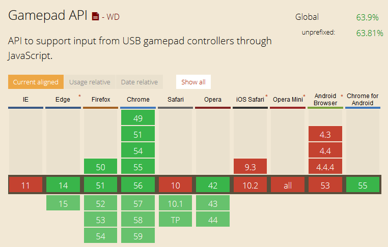
Chrome is experimenting with adding support for sensing Bluetooth inputs directly. Who knows where this will go...
http://caniuse.com/#feat=gamepad as of 1/31/17
Listen for changing canvas size, change the aspect ratio (which changes the viewing frustum), and notify the framework:
//from: http://stackoverflow.com/questions/641857/javascript-window-resize-event
/*  function: addEvent
    @param: obj         (Object)(Required)
      - The object which you wish to attach your event to.
    @param: type        (String)(Required)
      - The type of event you wish to establish.
    @param: callback    (Function)(Required)
      - The method you wish to be called by your event listener.
    @param: eventReturn (Boolean)(Optional)
      - Whether you want the event object returned to your callback method.*/

    var addEvent = function(obj, type, callback, eventReturn) {
      if(obj == null || typeof obj === 'undefined')
        return;

      if(obj.addEventListener)
        obj.addEventListener(type, callback, eventReturn ? true : false);
      else if(obj.attachEvent)
        obj.attachEvent("on" + type, callback);
      else
        obj["on" + type] = callback;
    };

    //An example call to the new addEvent function:
    var watch = function(evt) {
      //Older browser versions may return evt.srcElement
      //Newer browser versions should return evt.currentTarget
      var dimensions = {
        height: (evt.srcElement || evt.currentTarget).innerHeight,
        width: (evt.srcElement || evt.currentTarget).innerWidth
      };
      //https://threejs.org/docs/api/cameras/PerspectiveCamera.html
      renderer.setSize(dimensions.width, dimensions.height);
      camera.aspect = dimensions.width / dimensions.height;
      //here's another flag to alert the framework!
      camera.updateProjectionMatrix();
    };

    addEvent(window, 'resize', watch, true);
Notice that the apparent size of the image changes with the window:
Update aspect ratio AND (vertical) field-of-view angle.
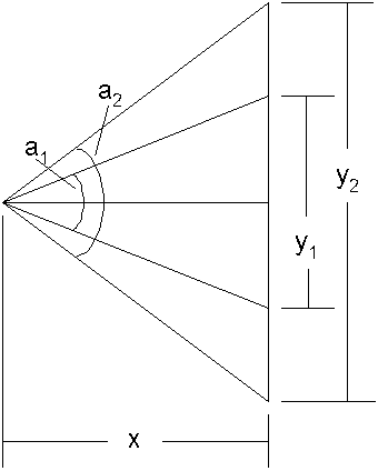
We want the view to stay the same size. We know a1 and y1 so we can calculate x.
When we know the new y2 and the old x (constant x -> constant apparent size) we can find the new field-of-view angle.
We have it right when these operations are reversible.
Update (vertical) field-of-view angle:
      var fovBaseX;
      var fovBase = 75;

      function calcFovBaseX(angle,y) {
        var ang = angle / 180.0 * Math.PI;
        ang *= 0.5;
        var x = (y * 0.5) / Math.tan(ang);
        return x;
      }

      function calcFovAngle(height) {
        var hgt = height * 0.5;
        hgt /= fovBaseX;
        var angle = 2.0 * Math.atan(hgt);
        var ang = angle / Math.PI * 180.0;
        return ang;
      }

      //fovBaseX = calcFovBaseX(75,500);  //returns 325.8063432103014
      //var k = calcFovAngle(500);        //returns 75!

      //basic initialization
      var aspectRatio = window.innerWidth/window.innerHeight;
      fovBaseX = calcFovBaseX(fovBase, window.innerHeight);
      var camera = new THREE.PerspectiveCamera(fovBase, aspectRatio, 0.1, 1000);

      //---------------------------------------
      //update when sensing resize
      renderer.setSize(dimensions.width, dimensions.height);
      camera.aspect = dimensions.width / dimensions.height;
      camera.fov = calcFovAngle(dimensions.height);  //new fov
      camera.updateProjectionMatrix();               //alert the framework!
This works whether we're viewing one image or two!
Here's how I incorporated this into a project of my own.
It defines the 3D shapes from existing 2D data.
It generates reports and is completely configurable. There's a looong To Do list that I'll be sawing away at over time. :-)
It's a discrete-event simulation framework composed of simple components including Arrival Generators, Entries, Queues, Processes, Bags (parking lots), Decision Points, Exits, and moving Entities.
We don't want to make lots of entities and rely on the garbage collector to dispose of the old ones...
    //create each entity
    function define3DEntity(x1,y1,bottomRadius,height,segments,faceColor,vertexColor) {
      var geometry = new THREE.CylinderGeometry(0,bottomRadius,height,segments);
      var material = new THREE.MeshPhongMaterial({
        color: faceColor,
        shading: THREE.FlatShading,
        polygonOffset: true,
        polygonOffsetFactor: 1,  //positive value pushes polygon farther away
        polygonOffsetUnits: 1
      });
      var cone = new THREE.Mesh( geometry, material );

      // wireframe
      var geo = new THREE.EdgesGeometry( cone.geometry );
      var mat = new THREE.LineBasicMaterial( { color: vertexColor, linewidth: 1 } );
      var wireframe = new THREE.LineSegments( geo, mat );
      cone.add( wireframe );

      cone.position.set(x1,(height+global3DComponentThickness),y1);
      scene.add( cone );
      setOf3DEntities.push(cone);
    }

    //define all entities we'll ever use, locate them out of frame
    function initGraphics3DEntities() {
      for (var i = 0; i < global3DMaxEntityCount; i++) {
        define3DEntity(10000, 10000, 5, global3DEntityHeight, 8, globalReadyColor, globalReadyVertexColor);
      }
      normalize3DEntities(0);  //parameter is starting index
    }

    //update one entity
    function update3DEntity(index,x1,y1,faceColor,vertexColor) {
      setOf3DEntities[index].material.color.setHex(colorToHex(faceColor));
      setOf3DEntities[index].children[0].material.color.setHex(colorToHex(vertexColor));
      setOf3DEntities[index].position.x = x1;
      setOf3DEntities[index].position.y = global3DTopHeight + (global3DEntityHeight / 2) + global3DNodeUpOffset;
      setOf3DEntities[index].position.z = y1;
    }

    //place unused entities out of frame
    function normalize3DEntities(startIndex) {
      if (startIndex > global3DMaxEntityCount) {
        alert("asked to normalize at too many 3D entities");
      }
      for (var i=startIndex; i < global3DMaxEntityCount; i++) {
        update3DEntity(i,10000,10000,globalReadyColor,globalReadyVertexColor);
      }
    }

    //update the characteristics of the scene, using only the entities needed
    function update3D() {
      //clearCanvas3D("#0000FF");
      var i;
      global3DRefreshEntityCount = 0;
      //change color of path- or box-components if applicable
      //then update entities associated with each component
      for (i = 0; i < numComponents; i++) {
        if (setOfComponents[i].getComponentType() != "Arrivals") {
          setOfComponents[i].graphic.update3DComponent();
          setOfComponents[i].graphic.update3DEntities();
        }
      }
      normalize3DEntities(global3DRefreshEntityCount);
    }  //update3D
...so we create a bunch at the beginning and use what we need for each update. The extras can be stored out of visual range.
Last but not least, adding 2D text to 3D scenes is almost too horrible to contemplate.
Nobody's figured out a really good way to do it yet.
Here's the relevant code if you're desperate to check it out:
      //define one label, a canvas mapped to a 2D plane
      function make3DLabel(text) {
        //create a canvas
        var canvas1 = document.createElement('canvas');
        var context1 = canvas1.getContext('2d');
        context1.canvas.width = 100;
        context1.canvas.height = 55;
        context1.fillStyle = "rgba(0,0,0,0.0)";
        context1.fillRect(0,0,200,200);
        context1.font = "28px Arial";
        context1.fillStyle = "rgba(255,0,0,1)";
        context1.textAlign="center";
        context1.fillText(text, 50, 35);

        // canvas contents will be used for a texture
        var texture1 = new THREE.Texture(canvas1)
        texture1.needsUpdate = true;

        var materialt = new THREE.MeshBasicMaterial({ map: texture1, side: THREE.DoubleSide });

        //create a 2D plane
        var plane = new THREE.Mesh(
            new THREE.PlaneGeometry(1, 0.5),
            materialt
          );

        if (axisFrames) {
          var geom = new THREE.EdgesGeometry( plane.geometry );
          var matl = new THREE.LineBasicMaterial( { color: 0xFFFF00, linewidth: 1 } );
          var wire = new THREE.LineSegments(geom, matl);
          plane.add(wire);
        }
        return plane;
      }

      //instantiate two labels
      xLabel = make3DLabel("X-axis");
      xLabel.position.set(3.5, 0, 0);
      scene.add(xLabel);
      xLabel.rotation.y = cAngle + halfPi;

      zLabel = make3DLabel("Z-axis");
      zLabel.position.set(0, 0, 3.5);
      scene.add(zLabel);
      zLabel.rotation.y = cAngle + halfPi;

      //--------------------------------
      //at the bottom of the cylRotations function

        xLabel.rotation.y = cAngle + halfPi;
        zLabel.rotation.y = cAngle + halfPi;
There are a few good discussions out there about better ways to do this.
This presentation and other information can be found at my website.
E-mail: bob@rpchurchill.com
LinkedIn: linkedin.com/in/robertpchurchill