Configure dynamic routing protocols to enable communication between multiple networks

Business Scenario
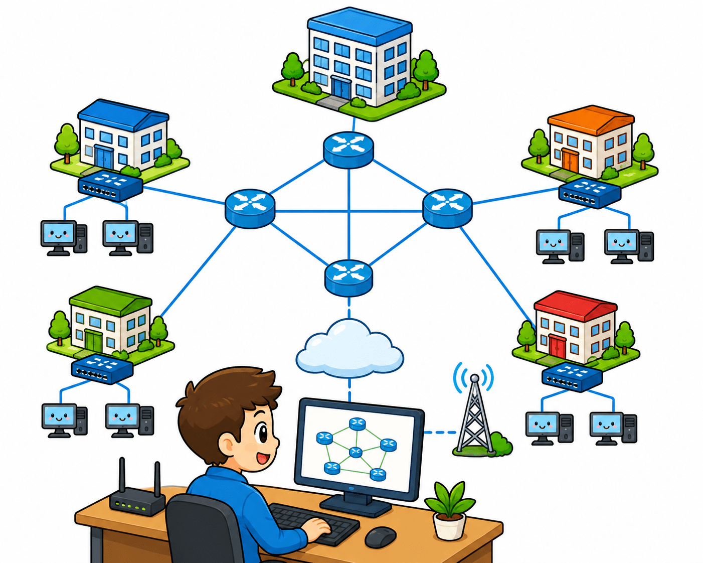
You are a Network Security Intern at SkyLink Networks, responsible for connecting multiple branch offices. Your task is to configure dynamic routing protocols like OSPF for efficient path selection, RIP for basic routing between networks, and understand how BGP enables communication across different organizations.By implementing and testing these protocols in Cisco Packet Tracer, you ensure seamless data flow and reliable
connectivity between all networks.

Pre-Lab Preparation
Topic :Network Routing & Communication
1) Routing Process - ARP DHCP NAT
2) Routing Protocols – BGP RIP OSPF
Task 1: Configuring Basic Dynamic Routing Using RIP. Implementing Efficient Routing with OSPF Establishing Inter-Network Routing Using BGP
Configure OSPF Routing :
1
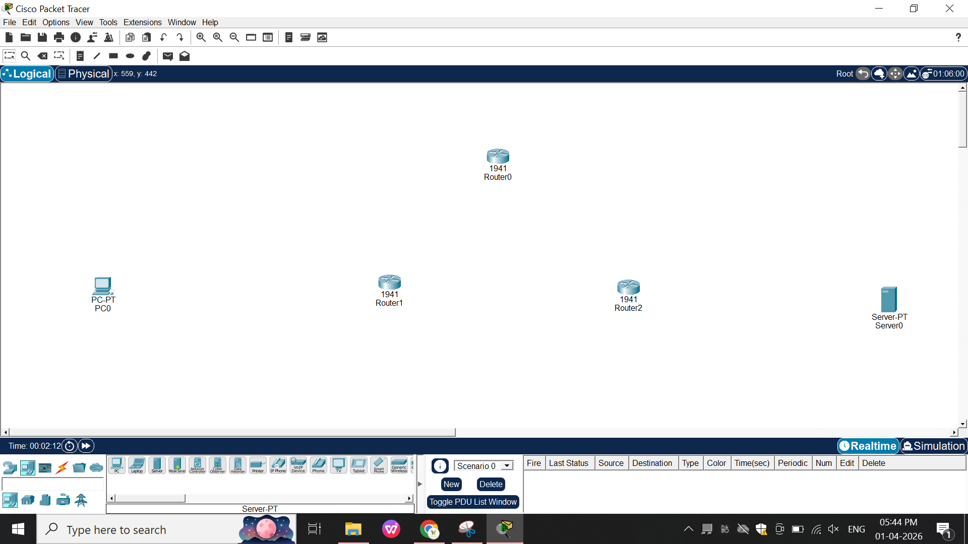
Add Devices in Packet Tracer
a
a
b
a
-
1 PC
-
1 Server
-
3 Routers (1841/1941)
Rename routers:
-
Router1 (Left)
-
Router3 (Top)
-
Router5 (Right)
2
Add Serial Modules (IMPORTANT)
3
Connect Devices
Click Router → Physical tab
a
a
b
a
c
a
d
a
e
a
a
a
Power OFF router
Drag HWIC-2T module
Insert into slot
Power ON
Do this For Router 1 and Router 3
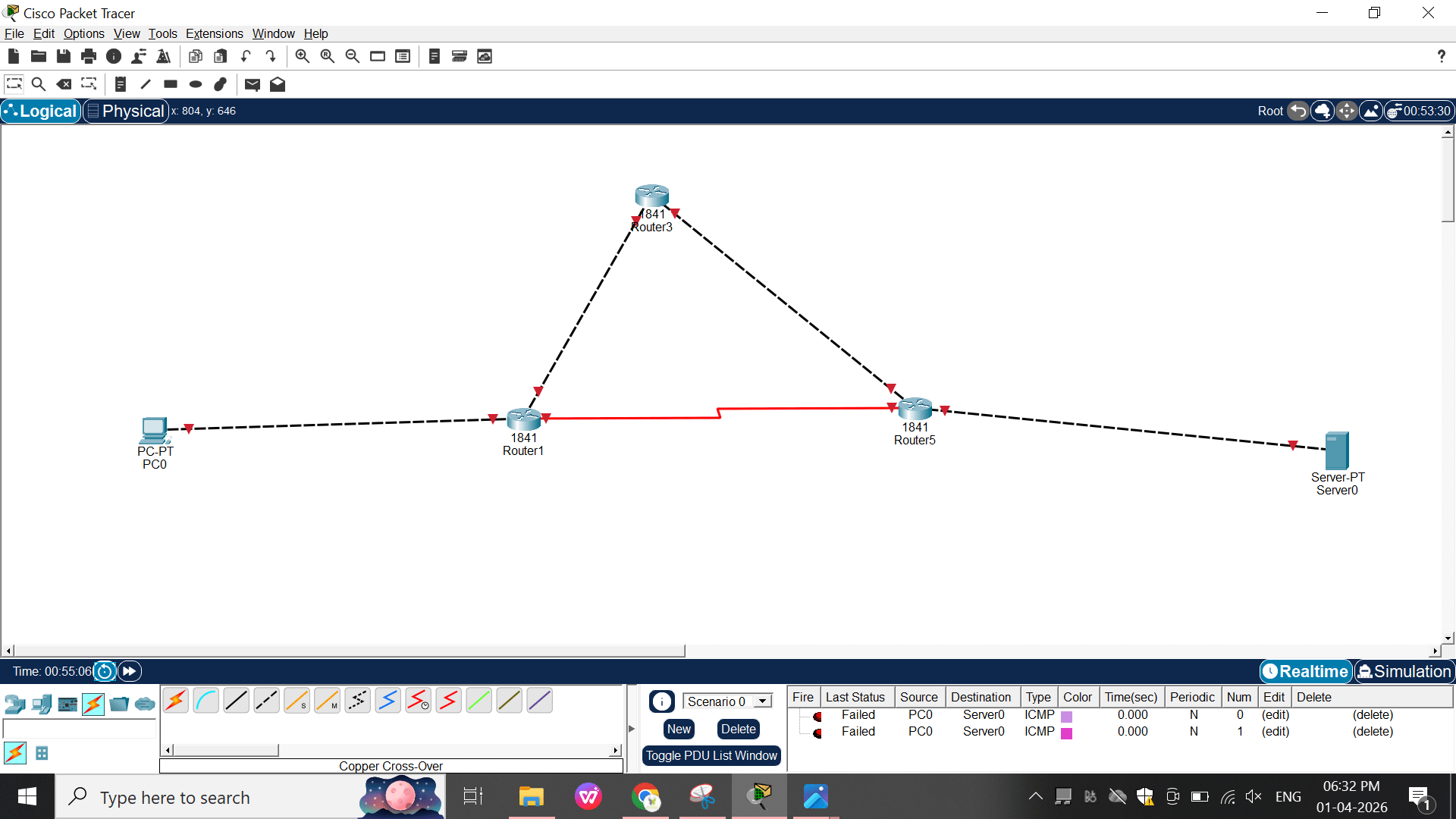
Use cables:
-
PC ↔ Router1 → Copper CrossOver
-
Router1↔ Router3 → Serial (DCE/DTE)
-
Router3 ↔ Router5 → Serial
-
Router1 ↔ Router5 → Serial (backup link)
-
Router5 ↔ Server → Copper Straight


IP Addressing
4
a
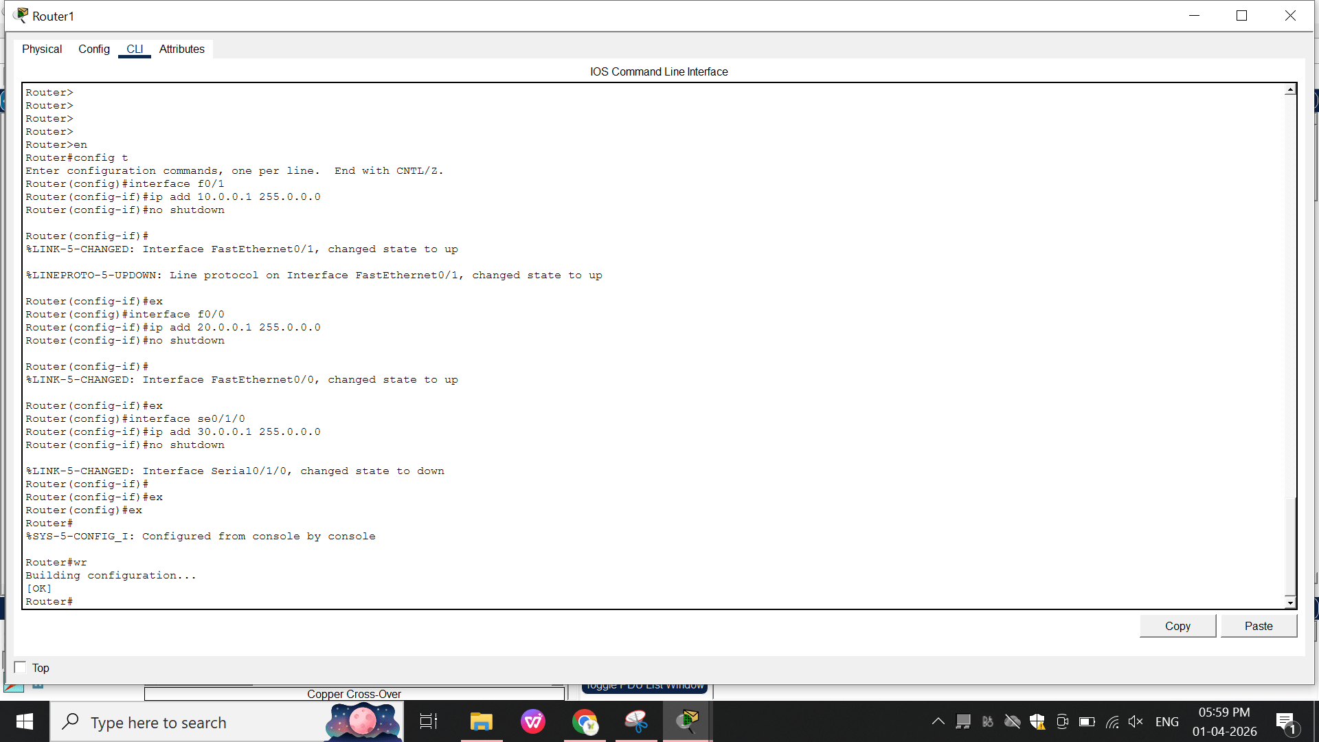
Router 1:
-
int f0/1
-
ip add 10.0.0.1 255.0.0.0
-
no shutdown
- int f0/0
- ip add 20.0.0.1 255.0.0.0
- no shutdown
- int se0/1/0
- ip add 30.0.0.1 255.0.0.0
- no shutdown
b
Router3 : Run this in R3
-
int f0/1
-
ip add 40.0.0.1 255.0.0.0
-
no shutdown
- int f0/0
-
ip add 20.0.0.2 255.0.0.0
-
no shutdown
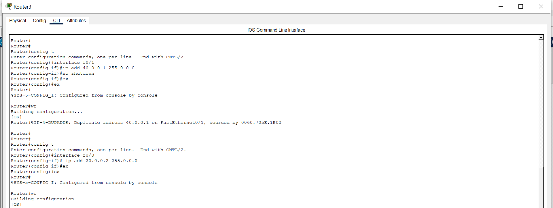
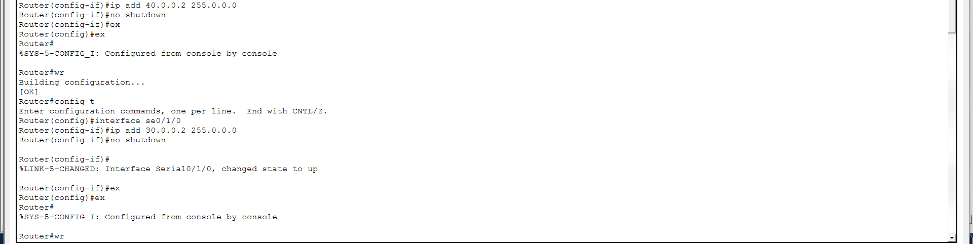
- int s0/1/0
- ip add 30.0.0.2 255.0.0.0
- no shutdown
Router5 : Run this command in R5
c
- int f0/0
- ip add 50.0.0.1 255.0.0.0
- no shutdown
- int f0/1
- ip add 40.0.0.2 255.0.0.0
- no shutdown

Configure OSPF Routing
5
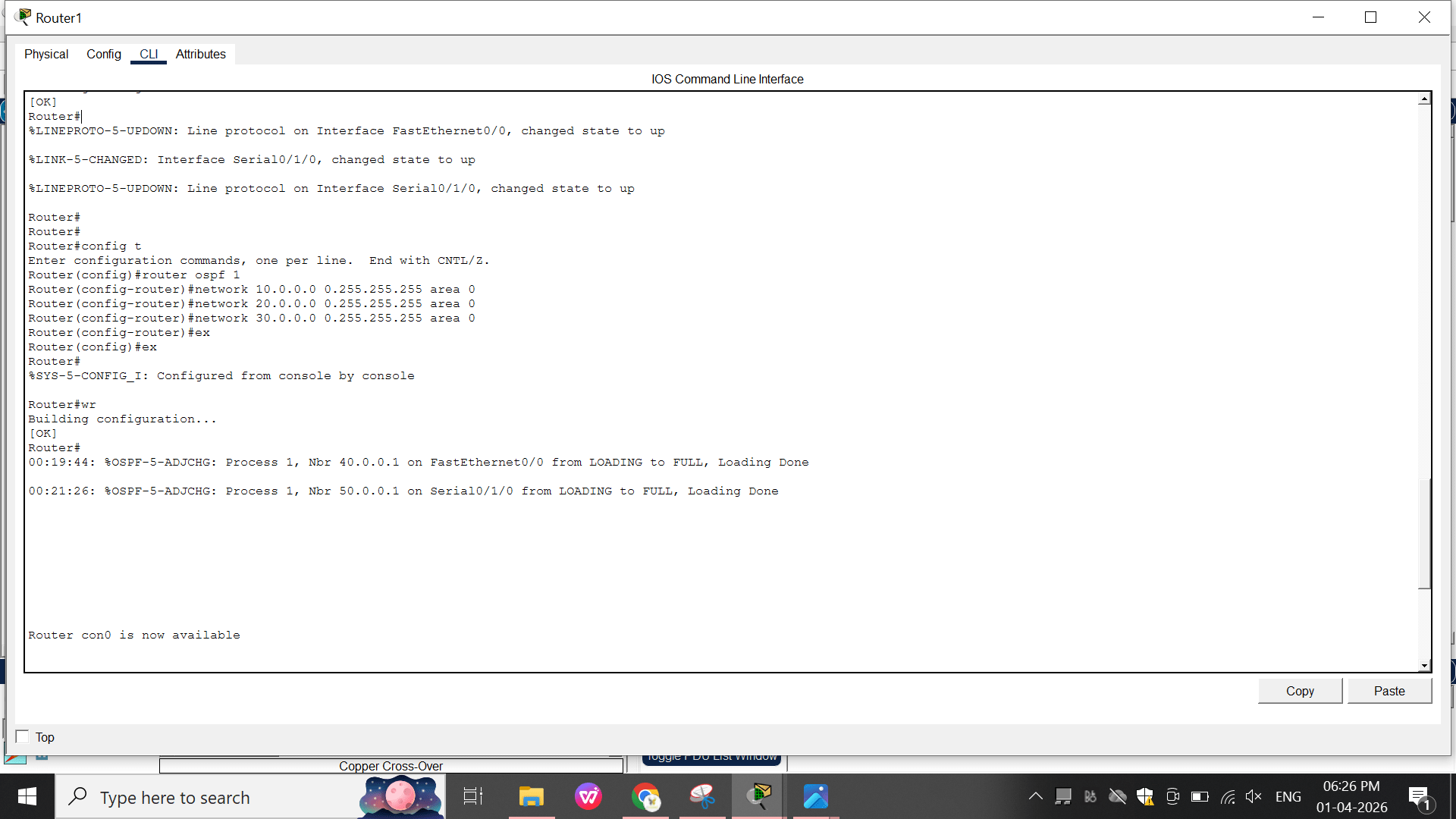
Router1
a
-
router ospf 1
-
network 10.0.0.0 0.255.255.255 area 0
-
network 20.0.0.0 0.255.255.255 area 0
-
network 30.0.0.0 0.255.255.255 area 0
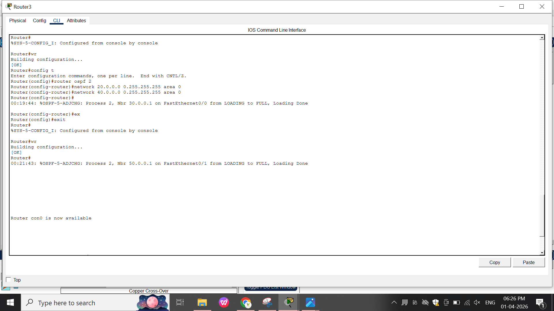
Router3
b
-
ex
- router ospf 2
- network 20.0.0.0 0.255.255.255 area 0
- network 40.0.0.0 0.255.255.255 area 0
- ex
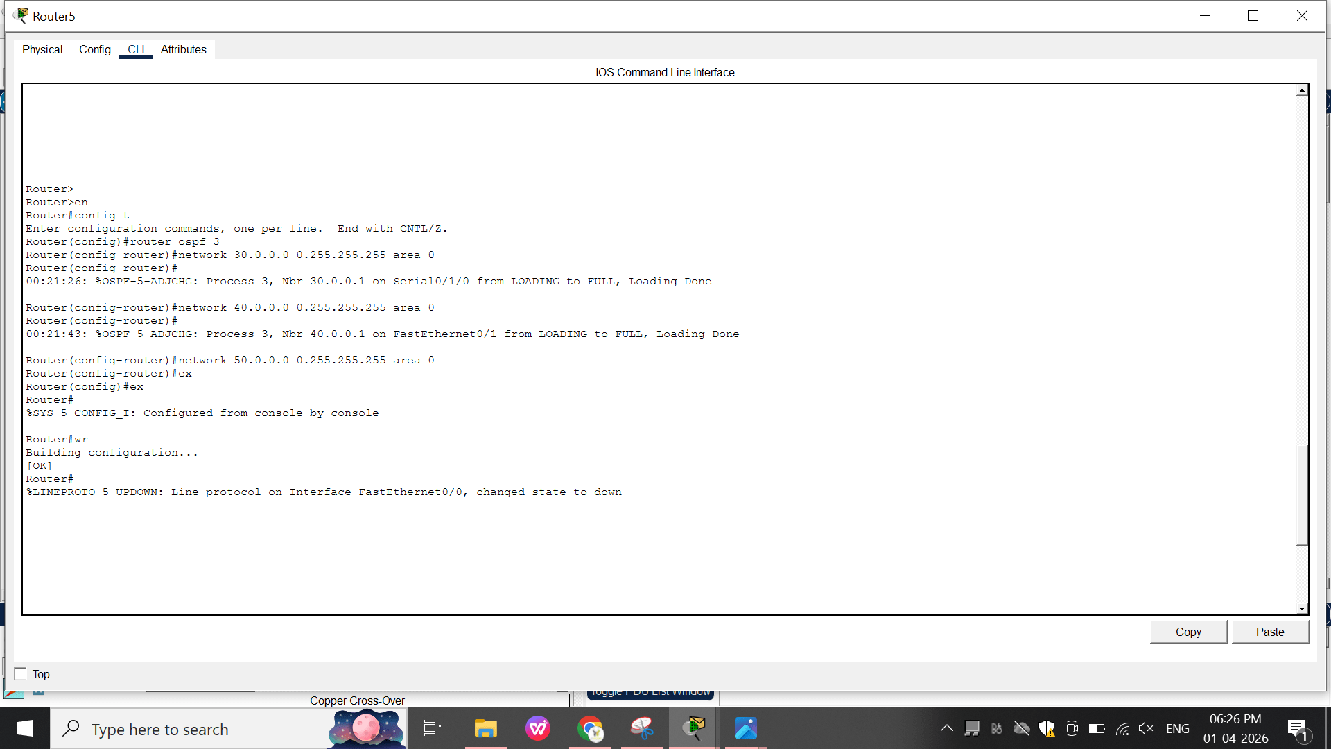
Router5
c
- router ospf 3
- network 30.0.0.0 0.255.255.255 area 0
6
Configure PC & Server
- network 40.0.0.0 0.255.255.255 area 0
- network 50.0.0.0 0.255.255.255 area 0
- ex
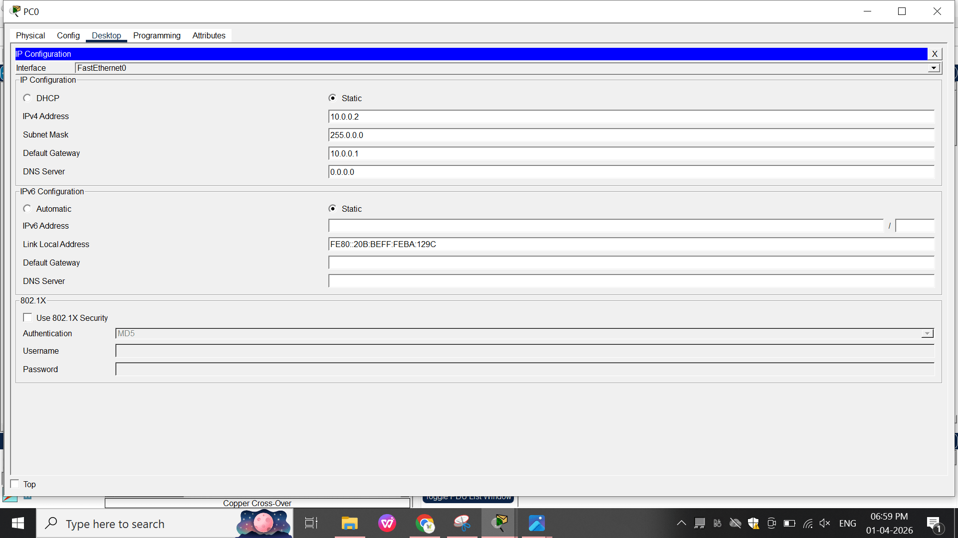
a
PC
-
IP: 10.0.0.2
-
Subnet: 255.0.0.0
-
Gateway: 10.0.0.1
b
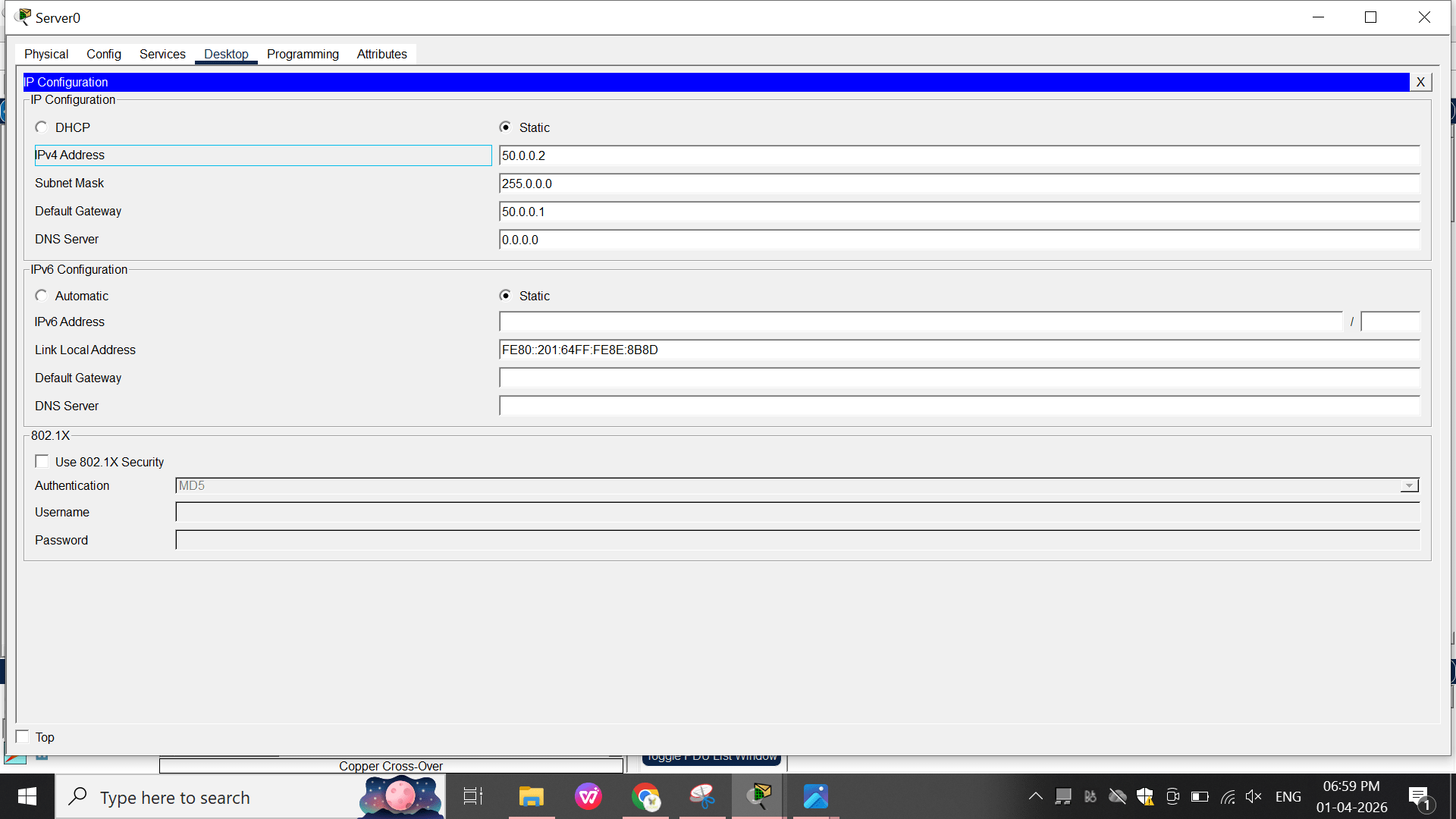
Server
-
IP: 50.0.0.2
-
Subnet: 255.0.0.0
-
Gateway: 50.0.0.1
Test Connectivity : open the pc and ping from command Prompt to ip 50.0.0.2

Task 2:Configuring Basic Dynamic Routing Using RIP
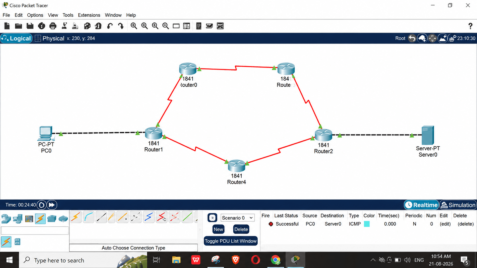
Place the Lab Devices
1
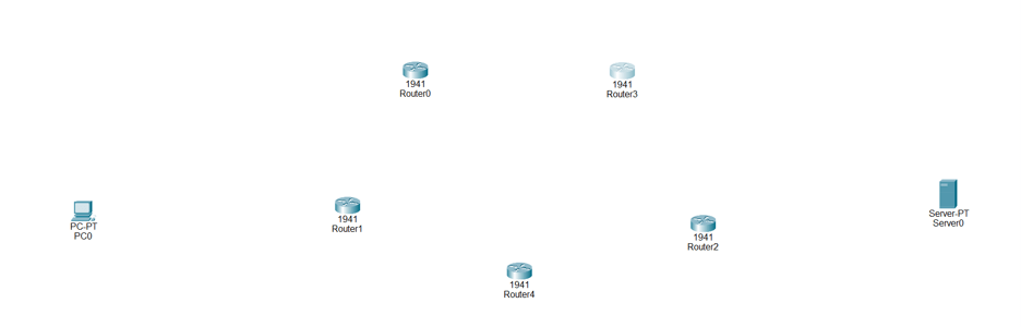
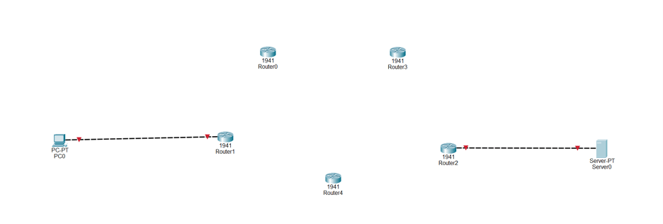
Add 5 Cisco 1941 Routers (Router0, Router1, Router2, Router3, Router4)
a
Add 1 End Device PC (PC0) and 1 Server (Server0)
b
Configure Router R 0 and R 1 For Basic Connectivity
2
Connect PC0 to Router1 using a Copper Straight-Through cable.
a
Connect Server0 to Router2 using a Copper Straight-Through cable.
b
Add HWIC-2T Modules to Routers
3
a
b
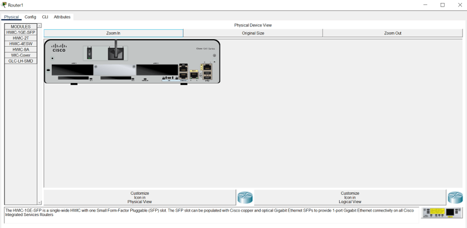
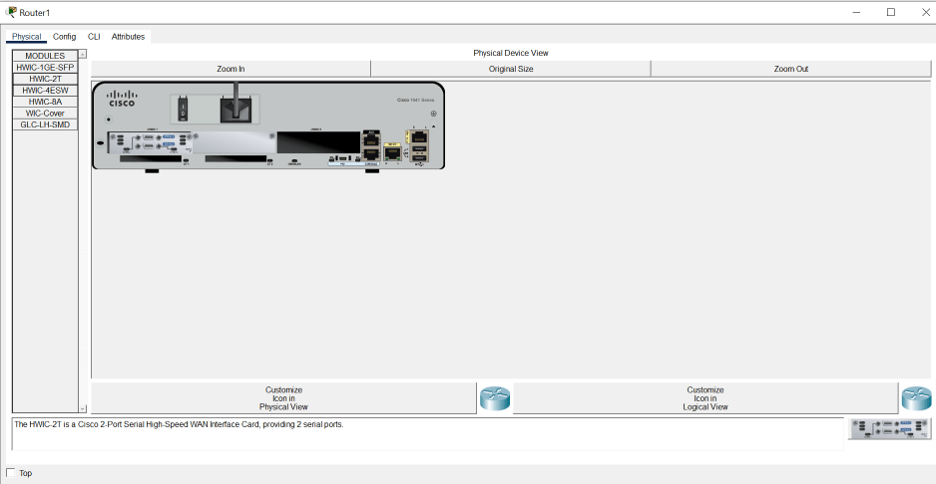
Click on each router (Router0 through Router4) and select the Physical tab.
Turn off the router power switch.
c
d
Drag the HWIC-2T module into an open HWIC slot to add Serial ports.
Turn the router power back on. Repeat this for all 5 routers.
Connect Router1 to Router0
4
a
b
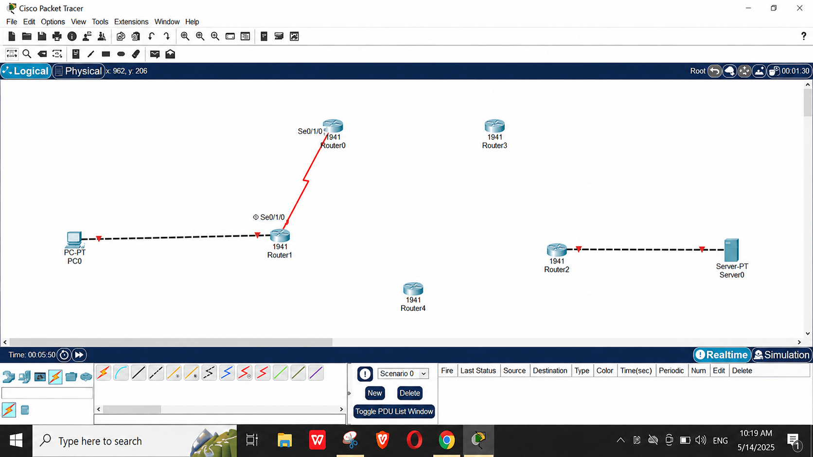
Select the Serial DCE cable.
Connect interface Se0/1/0 of Router1 to Se0/1/0 of Router0.
Connect Router1 to Router4
5
a
b
Select the Serial DCE cable.
Connect interface Se0/1/1 of Router1 to Se0/1/1 of Router4.
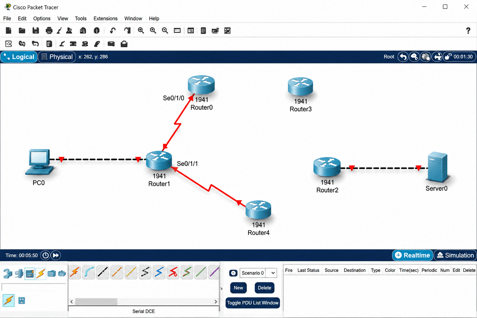
Connect Router0 to Router3
6
a
b
Select the Serial DCE cable.
Connect interface Se0/1/1 of Router0 to Se0/1/1 of Router3.
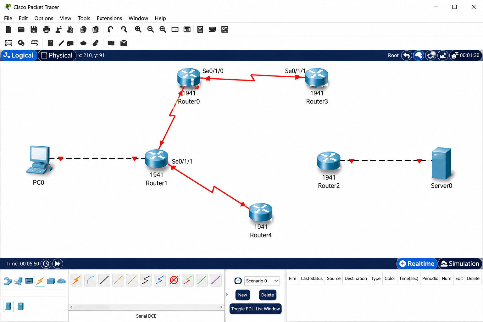
Connect Router3 to Router2
7
a
Select the Serial DCE cable.
b
Connect interface Se0/1/0 of Router3 to Se0/1/0 of Router2.
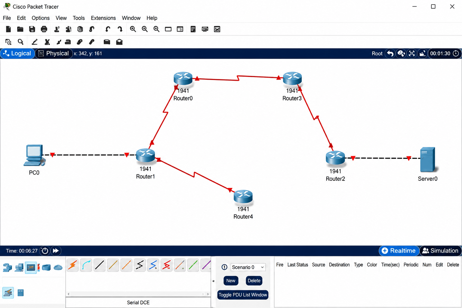
Complete the Topology Ring (Router4 to Router2)
8
a
Select the Serial DCE cable.
b
Connect interface Se0/1/0 of Router4 to Se0/1/1 of Router2.
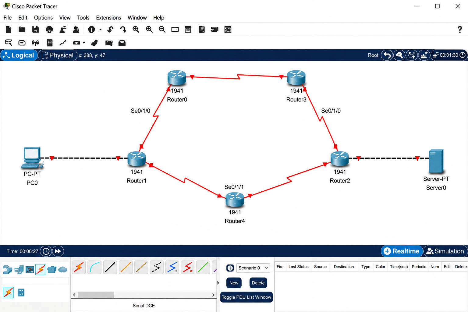
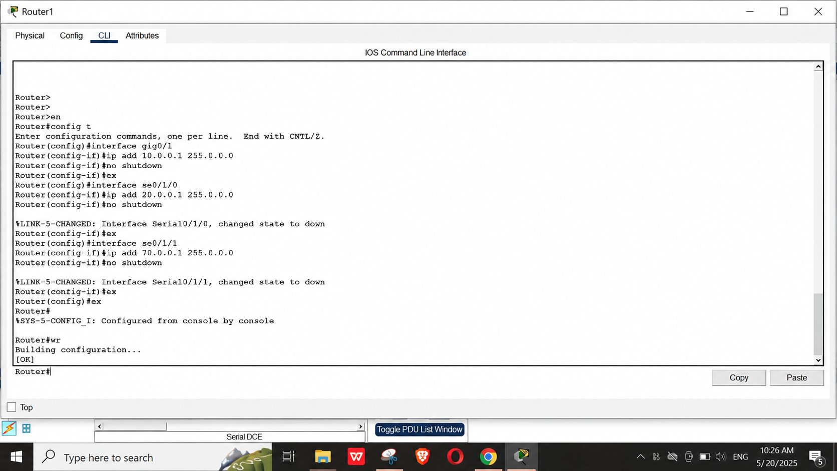
Configure Router Interfaces (Example for Router1)
9
a
Open Router1 CLI and assign IP addresses and bring up interfaces:
Router>en
Router#config t
Router(config)#interface gig0/1
Router(config-if)#ip add 10.0.0.1 255.0.0.0
Router(config-if)#no shutdown
Router(config-if)#ex
Router(config)#interface se0/1/0
Router(config-if)#ip add 20.0.0.1 255.0.0.0
Router(config-if)#no shutdown
Router(config-if)#ex
Router(config)#interface se0/1/1
Router(config-if)#ip add 70.0.0.1 255.0.0.0
Router(config-if)#no shutdown
Router(config-if)#ex
Router#wr
Configure Router0 Interfaces
10
a
Access Router0 CLI and enter:
Router>en
Router#config t
Router(config)#interface se0/1/0
Router(config-if)#ip add 20.0.0.2 255.0.0.0
Router(config-if)#no shutdown
Router(config-if)#ex
Router(config)#interface se0/1/1
Router(config-if)#ip add 30.0.0.1 255.0.0.0
Router(config-if)#no shutdown
Router(config-if)#ex
Router #wr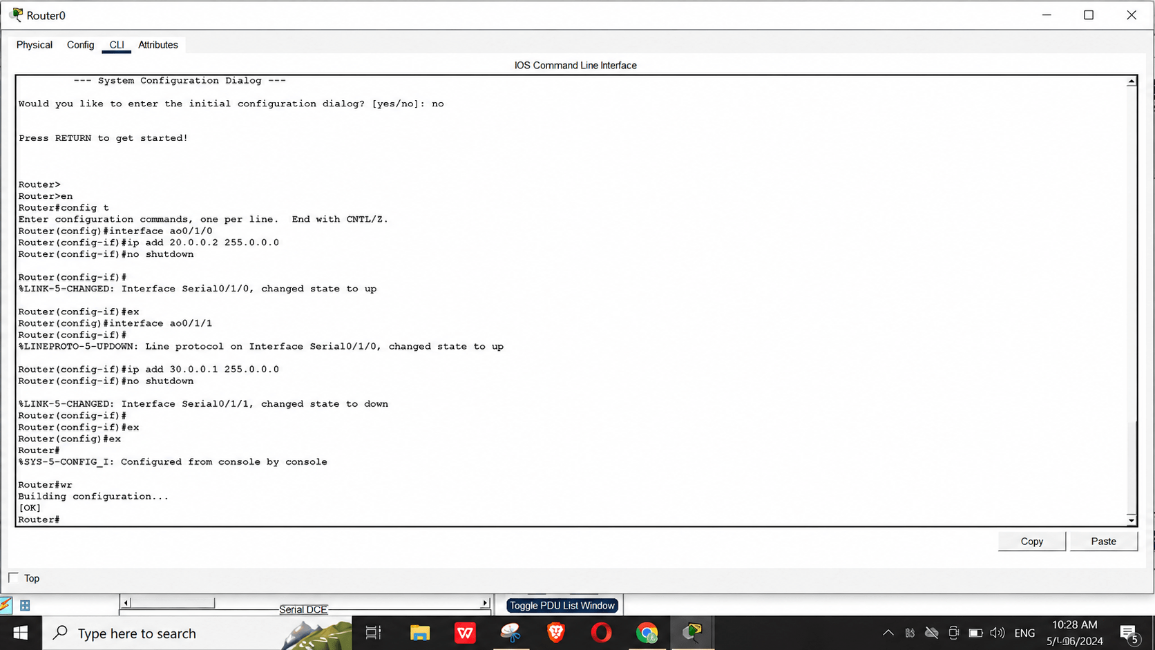
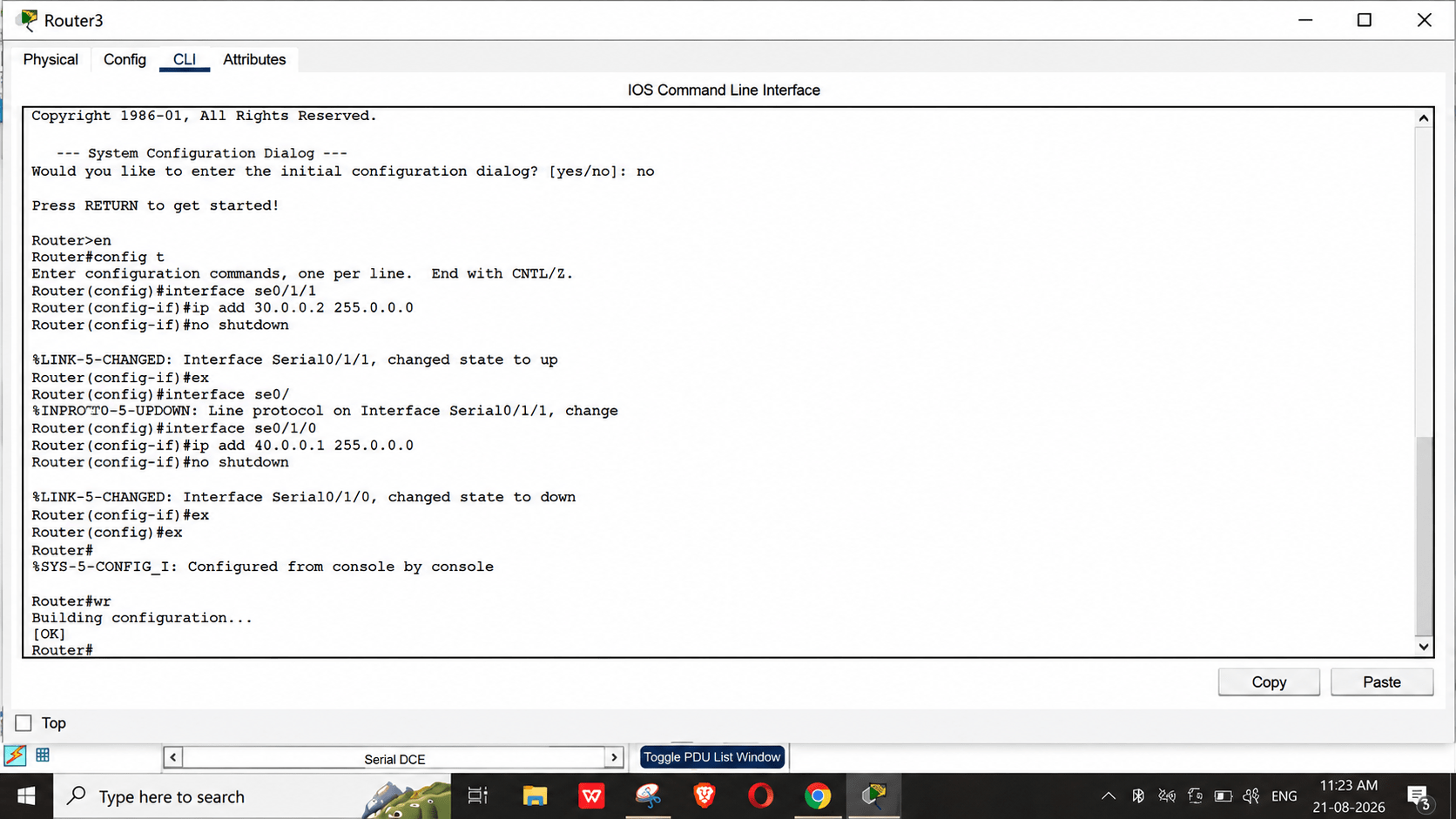
Configure Router3 Interfaces
11
a
Access Router3 CLI and enter:
Router>en
Router#config t
Router(config)#interface se0/1/1
Router(config-if)#ip add 30.0.0.2 255.0.0.0
Router(config-if)#no shutdown
Router(config-if)#ex
Router(config)#interface se0/1/0
Router(config-if)#ip add 40.0.0.1 255.0.0.0
Router(config-if)#no shutdown
Router(config-if)#ex
Router#wr
Configure Router2 Interfaces
12
a
Access Router2 CLI and enter:
Router>en
Router#config t
Router(config)#interface se0/1/0
Router(config-if)#ip add 40.0.0.2 255.0.0.0
Router(config-if)#no shutdown
Router(config-if)#ex
Router(config)#interface gig0/1
Router(config-if)#ip add 50.0.0.1 255.0.0.0
Router(config-if)#no shutdown
Router(config-if)#ex
Router(config)#interface se0/1/1
Router(config-if)#ip add 60.0.0.1 255.0.0.0
Router(config-if)#no shutdown
Router(config-if)#ex
Router#wr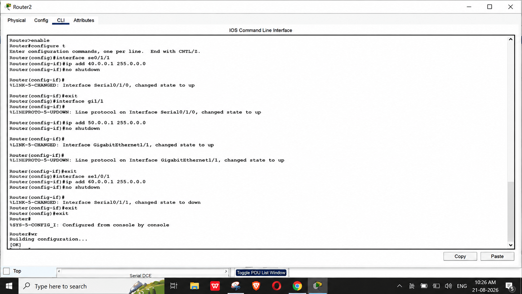
Configure Router4 Interfaces
13
a
Access Router4 CLI and enter:
Router>en
Router#config t
Router(config)#interface se0/1/0
Router(config-if)#ip add 60.0.0.2 255.0.0.0
Router(config-if)#no shutdown
Router(config-if)#ex
Router(config)#interface se0/1/1
Router(config-if)#ip add 70.0.0.2 255.0.0.0
Router(config-if)#no shutdown
Router(config-if)#ex
Router#wr
Router>en
Router#config t
Router(config)#interface se0/1/0
Router(config-if)#ip add 60.0.0.2 255.0.0.0
Router(config-if)#no shutdown
Router(config-if)#ex
Router(config)#interface se0/1/1
Router(config-if)#ip add 70.0.0.2 255.0.0.0
Router(config-if)#no shutdown
Router(config-if)#ex
Router#wr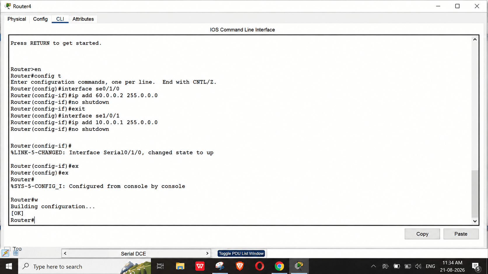
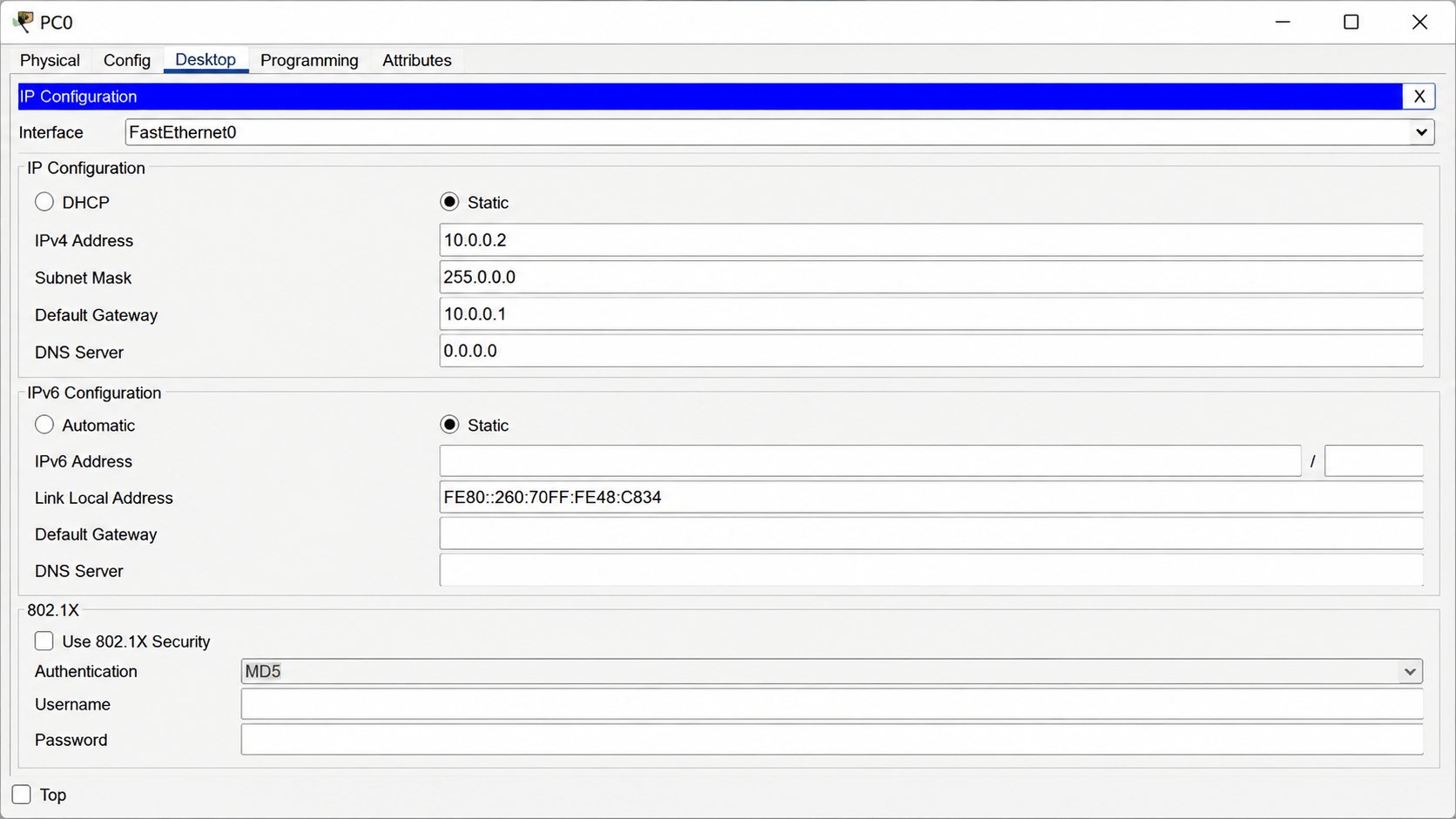
Configure PC0 IP Address
14
a
-
Click PC0 > Desktop tab > IP Configuration.
-
Select Static and set:
-
IPv4 Address: 10.0.0.2
-
Subnet Mask: 255.0.0.0
-
Default Gateway: 10.0.0.1
-
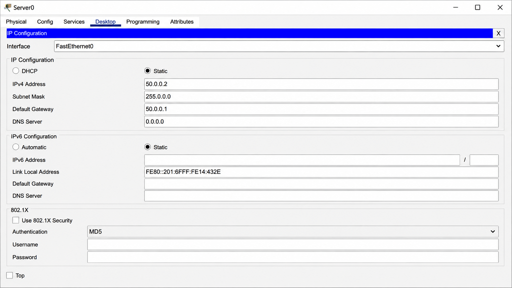
Configure Server0 IP Address
15
a
-
Click Server0 > Desktop tab > IP Configuration.
-
Select Static and set:
-
IPv4 Address: 50.0.0.2
-
Subnet Mask: 255.0.0.0
-
Default Gateway: 50.0.0.1
-
Configure RIP on Router1
16
a
Access Router1 CLI and enter:
Router>en
Router#config t
Router(config)#router rip
Router(config-router)#network 10.0.0.0
Router(config-router)#network 20.0.0.0
Router(config-router)#network 70.0.0.0
Router(config-router)#ex
Router#wr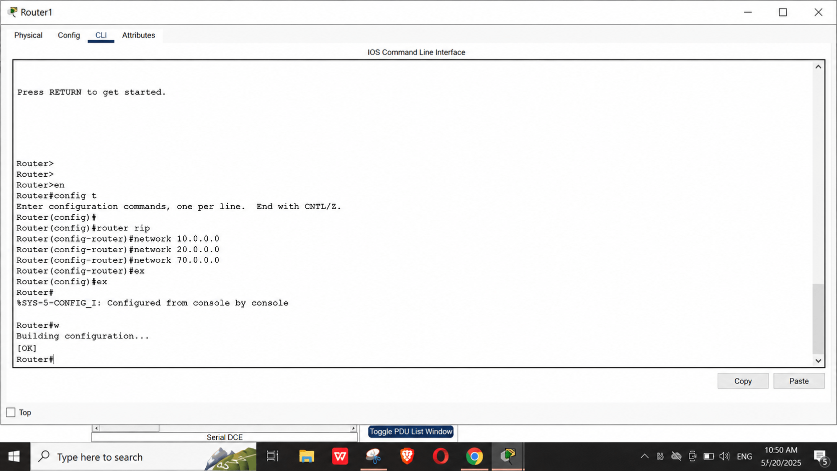
Configure RIP on Router0
17
a
Access Router0 CLI and enter:
Router>en
Router#config t
Router(config)#router rip
Router(config-router)#network 20.0.0.0
Router(config-router)#network 30.0.0.0
Router(config-router)#ex
Router#wr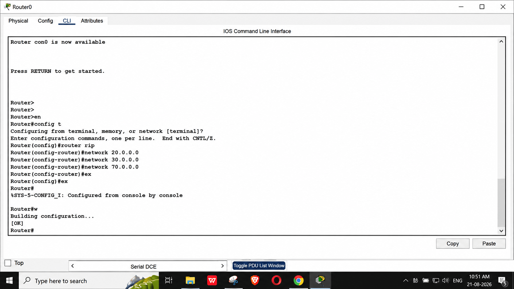
Configure RIP on Router3
18
a
-
Access Router3 CLI and enter:
-
Plaintext
Router>en
Router#config t
Router(config)#router rip
Router(config-router)#network 30.0.0.0
Router(config-router)#network 40.0.0.0
Router(config-router)#ex
Router#wr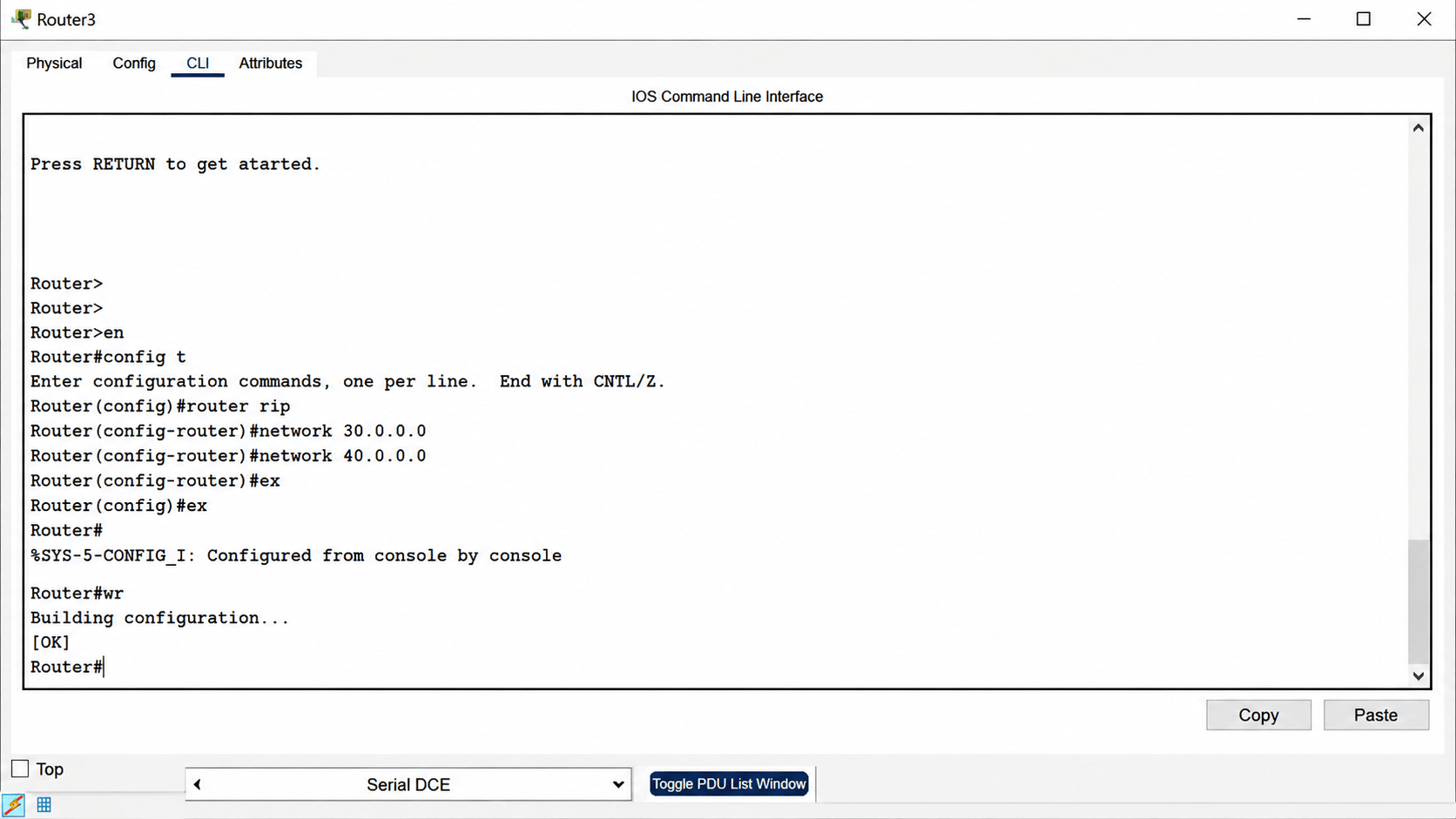
Configure RIP on Router2
19
a
-
Access Router2 CLI and enter:
-
Plaintext
Router>en
Router#config t
Router(config)#router rip
Router(config-router)#network 40.0.0.0
Router(config-router)#network 50.0.0.0
Router(config-router)#network 60.0.0.0
Router(config-router)#ex
Router#wr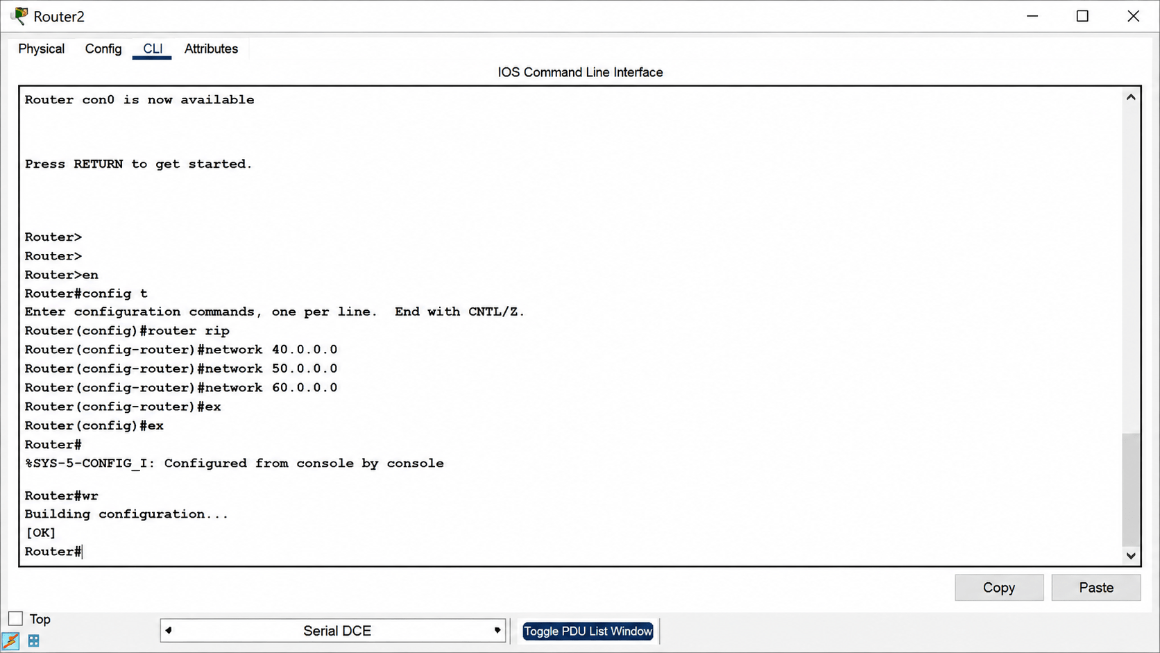
Task 3: Establishing Inter-Network Routing Using BGP
1
2
Run Command
- Default Route : From your screen : 0.0.0.0 0.0.0.0 192.168.0.1
BGP also works like this — it decides where to send unknown networks on the Internet
Directly Connected Networks
Example: 192.168.0.0 On-link
Explain:
-
This network is directly connected
-
No router needed
a
Route print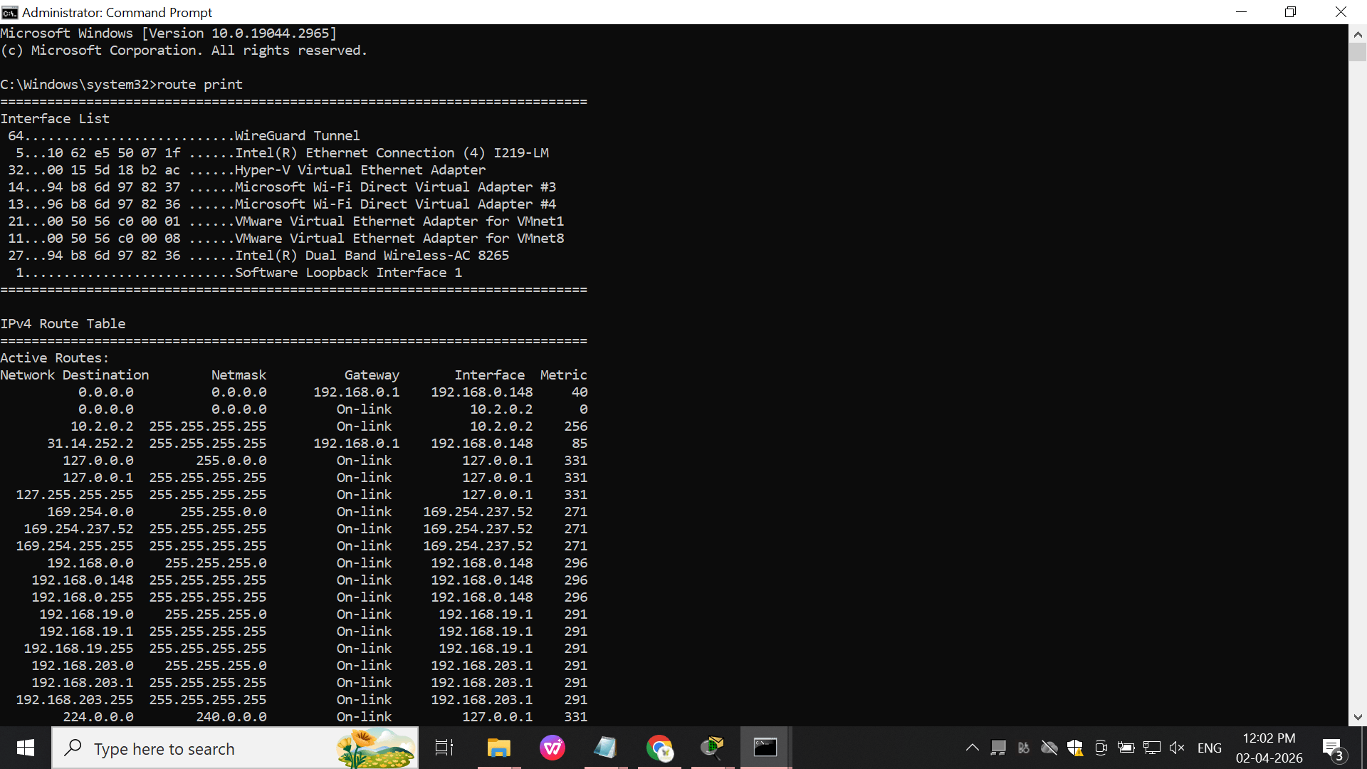
Multiple Networks (Important for BGP)
3
From your screen:
-
192.168.19.0
-
192.168.203.0
-
10.2.0.2
a
BGP’s job is to share these networks between different organizations
Great job!
You have successfully configured dynamic routing protocols to enable communication between multiple networks.
In this lab, you have:
Understood the purpose of dynamic routing, Configured a routing protocol (RIP / OSPF / EIGRP), Added correct network statements, Enabled routing on the required interfaces, Verified routing tables using show ip route, Tested connectivity between different networks, Confirmed end-to-end communication between devices.
You are now ready to move to advanced networking concepts.
Checkpoint
Next-Lab Preparation
Topic :Network Security & Protection
1.Proxy/Proxy Server And VPN
2.IDS IPS and Firewall