GL 2.1 Advance Systems High-Performance Powerplants and Constant Speed Propeller
Rev 03/2025

Disclaimer
Students should use their textbooks, syllabus, and Airman Certification Standards (ACS) as their primary sources of information. EcFlight is an online training tool designed to simplify and enhance your ground school learning experience. However, it is not a substitute for FAA- or school-approved study materials. Before using these slides for study, always refer to your officially approved resources, such as the Jeppesen physical or electronic book and other FAA-approved materials.
Reference Books
- (Faa), Federal Aviation Administration. Aviation Maintenance Technician Handbook--Airframe. Aviation Supplies & Acade, 2018. Vol 1 and 2
- FEDERAL AVIATION ADMINISTRATION (FAA). AVIATION MAINTENANCE TECHNICIAN HANDBOOK: Powerplant. AVIATION SUPPLIES & ACADE, 2018.
- Instrument Commerical Syllabus. 2016.
Reference Media
- https://www.flyingmag.com/best-used-six-seaters/
- https://www.flickr.com/photos/23629083@N03/2373924473/sizes/o/
- https://www.team-bhp.com/forum/commercial-vehicles/180393-experience-british-airways-concorde-simulator.html
- https://www.pistonheads.com/news/general-pistonheads/what-is-mechanical-fuel-injection-ph-explains/37478
- https://www.aircraftsystemstech.com/p/fuel-injection-systems.html
- https://www.flickr.com/photos/wingmanphoto/7166462682/in/photostream/
- https://www.cartechbooks.com/techtips/anatomy-of-a-turbocharger-whats-inside-and-how-it-works/
- https://www.ctsys.com/blog/entry/mountain-flying-safety-preparation-tips-and-challenges.html
- https://www.aopa.org/news-and-media/all-news/2015/june/flight-training-magazine/technique--constant-speed-propeller
- http://mail.lancair.net:81/Lists/lml/Message/38218.html?Language=finnish
- https://airandspace.si.edu/collection-objects/hamilton-standard-china-clipper-propeller-constant-speed-three-blade-metal
- (N.d.-b). Retrieved from https://generalaviationnews.com/2020/05/11/ask-paul-why-is-my-oil-temperature-so-high/.
Index

Fuel Injection Sytem
Comparison to Carburated Systems
-
Carburetors: Simple and cost-effective but can be inefficient.
- Susceptible to carburetor ice due to temperature drop from the venturi effect and fuel vaporization.
- Carburetor heat helps prevent icing but reduces engine power and enriches the fuel/air mixture.
- Uneven fuel distribution can cause spark plug fouling, rough idle, and reduced power output.
-
Fuel Injection Systems: More efficient and reliable.
- Less risk of induction ice and better fuel distribution.
- Improved combustion efficiency leads to better fuel economy, range, and endurance.
- More power for weight, lower operating temperatures, and reduced vibration.
Fuel Injection System Design and Operation
Components
In a fuel injection system, the fuel is injected directly into the cylinders, or just ahead of the intake valve. It includes the following components:
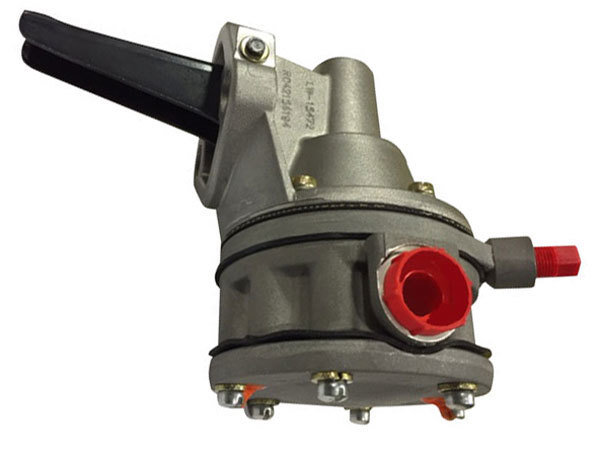
Engine Driven Fuel Pump
- The purpose of the Engine Driven Fuel Pump is to retrieve the fuel from the fuel tanks and send it to the Fuel Control Unit. Its output varies with engine speed.
- Whenever too much fuel is drawn to the Fuel Control Unit, the excess returns to a reservoir located below the engine, which also traps sediments and water that should be drained before any flight.
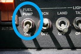
Fuel Pump
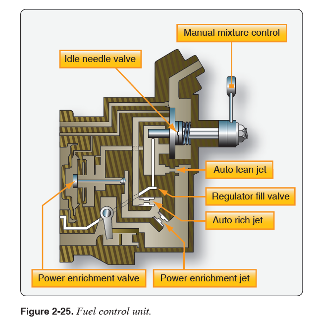
Fuel Control Unit
- This control unit, which essentially replaces the carburetor, meters fuel based on the mixture control setting and sends it to the fuel manifold valve at a rate controlled by the throttle.
- To achieve an ideal mixture ratio. The system also incorporates a manual mixture control to compensate for decreased air densities to avoid engine roughness, reduction in power output or even spark plug fouling.
Fuel Control Unit
Text
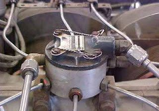
Fuel Manifold
- The fuel manifold was created to distribute fuel evenly to all the cylinders. It incorporates a fuel shutoff whenever the mixture control is placed in the idle position.
- After the fuel passes through the fuel manifold, it is then redirected to the fuel discharge nozzles.
Fuel Manifold
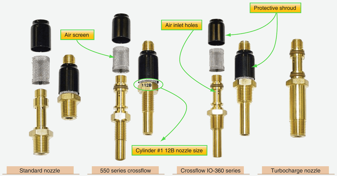
Discharge Nozzles
- The discharge nozzles, which are located in each cylinder head, inject the fuel-air mixture directly into each cylinder intake port.
- The action of injecting the fuel-air mixture directly into the cylinders allows atomizing (Fuel atomization means breaking the fuel into small particles which can further be mixed/emulsified with the air in order to ensure proper Air-Fuel Ratio for combustion) the fuel so it can easily evaporate inside each cylinder.
Discharge Nozzles
Auxiliary Pump
- An Electric Fuel Pump or Auxiliary Pump is used for engine start, to deliver fuel to the cylinders when the engine-driven pump is not running yet.
- It is also used to purge the system of vapors, and as a backup, in the event, the engine-driven fuel pump fails in flight. It should be used in accordance with manufacturers' recommendations to avoid generating excessively rich mixture while operating the aircraft.
Auxiliary Pump
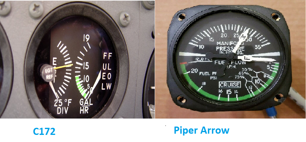
Fuel Flow Indicator
- The Fuel Flow indicator is used to determine how much fuel the engine is burning per hour. When it drops dramatically, it alerts the pilot that a problem with the engine-driven fuel pump has occurred.
- In addition, some indicators may include range markings to allow for mixture adjustments in order to obtain the best economy or best power mixture for various power settings.
Fuel Flow Indicator
Mixture Control
Adjusting the mixture control ensures the correct fuel/air ratio for optimal engine performance. As altitude increases, air density decreases, making the mixture too rich, which can cause power loss and spark plug fouling. Leaning the mixture prevents this issue. During descent, the mixture must be enriched to avoid running too lean, which can lead to high engine temperatures and potential engine damage. Proper mixture management, guided by the AFM/POH, helps maintain engine efficiency and longevity.
Fuel Pumps
- Fuel injection systems rely on fuel pumps to deliver fuel under pressure.
-
Typically, two fuel pumps are used:
- Engine-driven pump: Operates whenever the engine is running.
- Electric (auxiliary) pump: Used for starting and emergency situations.
- Misuse of the electric pump can cause excess fuel pressure, leading to rough engine operation or even engine stoppage.
- Some engine-driven pumps deliver more fuel than needed, with excess fuel returning to a reservoir tank.
- Preflight fuel drain checks are crucial to avoid contamination-related engine failures.
-
Shock cooling risk: Sudden fuel injection into hot cylinders can cause cracks due to rapid temperature changes.
- Prevent this by making gradual power adjustments and enriching the mixture in small increments.
- Some aircraft measure fuel flow in pounds per hour rather than gallons due to fuel density changes with temperature.
-
Fuel flow indicators actually measure fuel pressure:
- A sudden increase in fuel flow readings may indicate a clogged injector nozzle.
- Cross-check engine instruments to avoid excessive leaning, which can cause engine damage or failure.
Operational Considerations
Operating Procedures
- The operating procedures used in fuel-injected systems vary from the ones used in carburetor systems. Always check the appropriate POH on the proper procedures to use with your aircraft's specific systems.
- The system tends to be more challenging to operate. However, they have several advantages over carburetor models, the biggest being the fact that they are less prompt to induction icing.
Normal, Hot and Flooded Starts
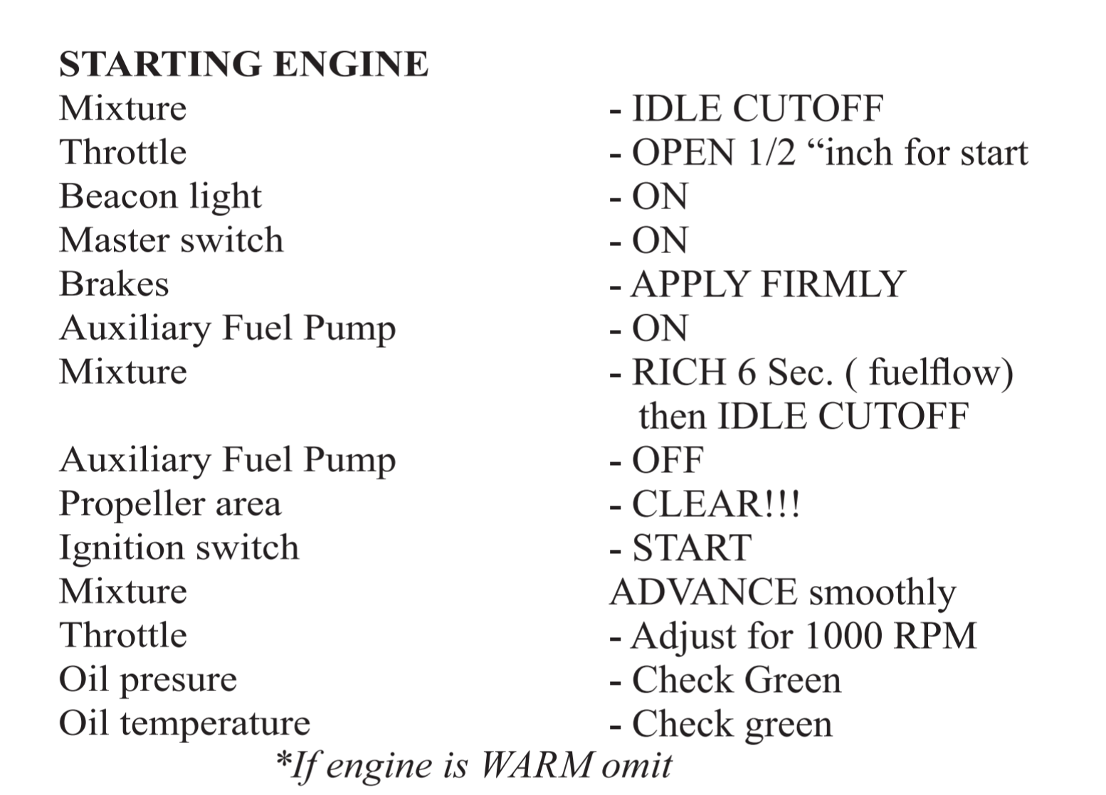
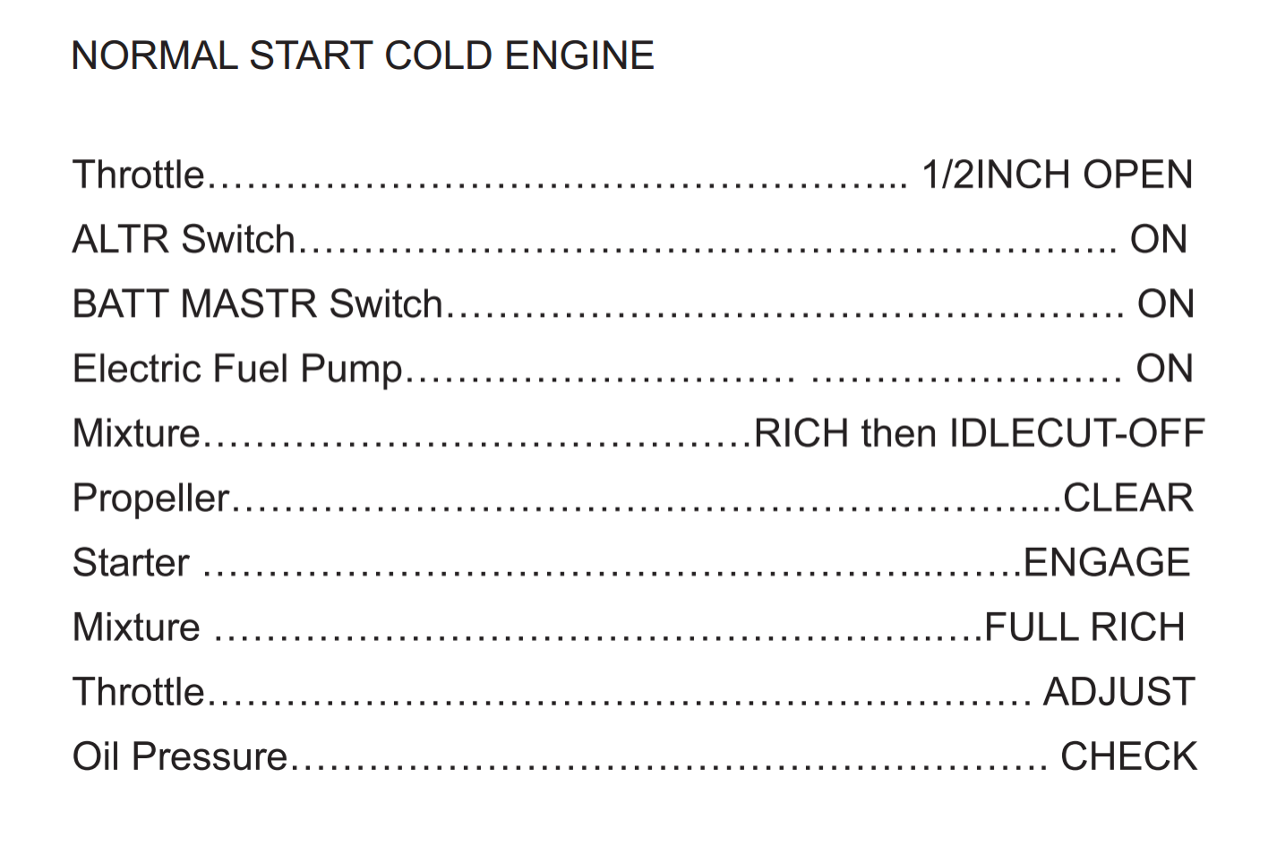
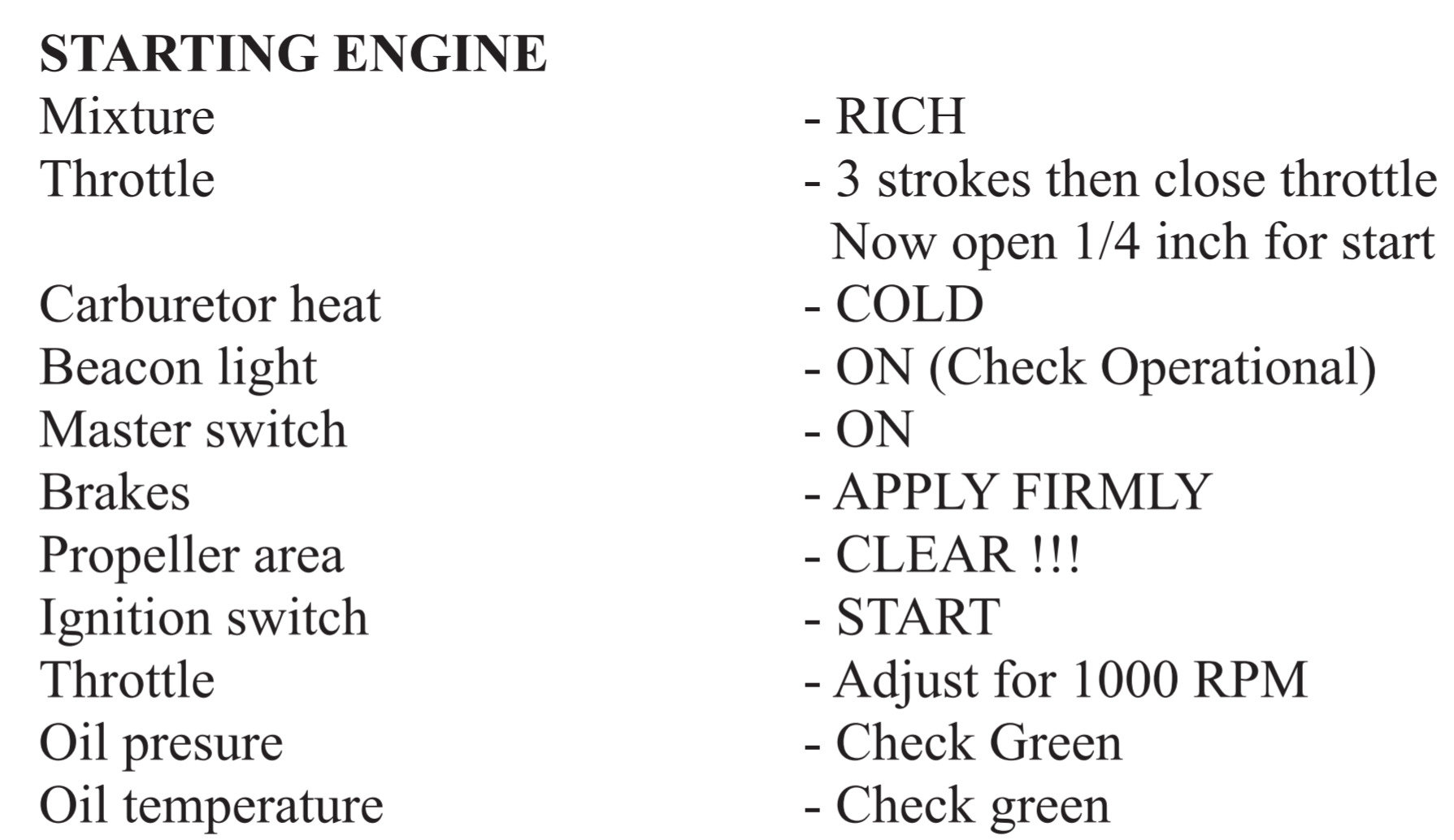
Normal Starts
- Normal Starts should be used whenever there is mild to warm ambient temperature.
- Generally, the throttle is advanced slightly. When the engine fires, the mixture should be pushed forward to allow fuel into the cylinder, followed by a smooth throttle input as necessary.
- Always refer to the appropriate checklist for the aircraft being flown.
C 172 M & SP
Arrow
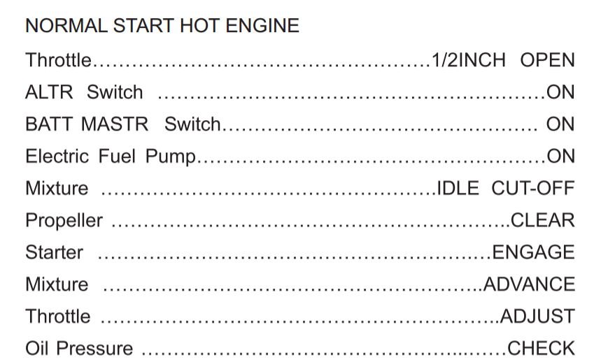
Hot Starts
- A fuel-injected system has a tendency of being hard to start after it has been running for an extended period of time. This is caused by the fuel's trend to boil and vaporize (vapor lock), which interferes with fuel flow and pumping.
- To prevent this, is recommended to follow the manufacturer's checklist and perform the recommended procedures. Generally, the throttle is advanced as the engine is cranking to allow a greater flow of air and fuel through the lines.
Checklist
Flooded Starts
- If too much fuel is allowed to flow to the engine after the fuel pump has been turned on, the engine may flood with excess fuel. If the engine doesn't start after 20 seconds. Let it cool off for 30 seconds before attempting to start it again, otherwise, starter damage may occur.
- For flooded starts, advance the throttle to the full open position, and crank until the engine fires, then advance the mixture control and retract the throttle to avoid overspeeding the engine.
Engine Shutdown
If the ignition switch is left on, moving the propeller can start the engine unexpectedly, even with the battery and master switches off, because magnetos require no external power. A broken ground wire in the ignition system can also cause the magneto to fire unintentionally. To check for this issue, momentarily turn the ignition switch OFF while idling—if the engine continues running, the system needs inspection. Always follow AFM/POH shutdown procedures to ensure safety.
Engine Monitoring
Aircraft equipped with high-performance engines typically have exhaust gas temperature and cylinder head temperature gauges to monitor engine conditions to achieve an overall increase in performance.
Oil Temperature and Pressure Gauges
- Oil lubricates engine components and helps dissipate heat.
- The oil pressure gauge indicates if the oil system is functioning properly.
- Low oil pressure may result from an oil pump failure or a leak.
- High oil pressure could indicate a clogged oil line.
- Abnormal oil pressure means critical engine parts may not be properly lubricated.
- If oil pressure does not rise within 30 seconds (warm weather) or 60 seconds (cold weather), engine shutdown is recommended per AFM/POH procedures.
Exhaust Gas Temperature Gauge
- The EGT gauge measures the temperature of the gases at the exhaust manifold. This temperature varies with the ratio of fuel to air entering the cylinders and can be used to find the correct leaning setting.
- Most manufacturers recommend leaning the mixture for the best power setting, in which the airplane is producing the most amount of power it can while producing less heat at the same time. To achieve this, the pilot should lean towards the rich side of Peak EGT.
Leaning with EGT
Cylinder Head Temperature Gauge
- Most aircraft are equipped with a cylinder-head temperature gauge that indicates a direct and immediate cylinder temperature change.
- A red line on the instrument indicates the maximum allowable cylinder head temperature.
- To avoid excessive cylinder head temperatures, increase airspeed, enrich the fuel-air mixture, deploy cowl flaps if equipped and reduce power.
Abnormal Combustion
Detonation
It is an uncontrolled, explosive ignition of the fuel-air mixture within the cylinder’s combustion chamber. It causes excessive temperatures and pressures, which, if not corrected, can quickly lead to failure of the piston, cylinder, or valves.
Causes
- Use of a lower fuel grade than that specified by the aircraft manufacturer.
- Operation of the engine with extremely high manifold pressures in conjunction with low rpm.
- Operation of the engine at high power settings with
an excessively lean mixture. - Maintaining extended ground operations or steep climbs in which cylinder cooling is reduced.
Preignition
Preignition occurs when the fuel-air mixture ignites prior to the engine’s regular ignition—usually caused by a residual hot spot in the combustion chamber. Preignition causes the engine to lose power and produces high engine temperatures.
Causes
- Carbon deposits form around spark plugs due to improper leaning during taxing or flight.
- Cracked spark plugs insulators.
- Damage in the cylinder that causes a part to heat sufficiently to ignite the fuel-air charge.
Induction Icing
- Even though fuel-injected systems are less prompt to icing conditions, it can still form over the air intake filter or air scoop whenever operating in visible moisture in temperatures at or below freezing, which will cause a significant reduction in engine power.
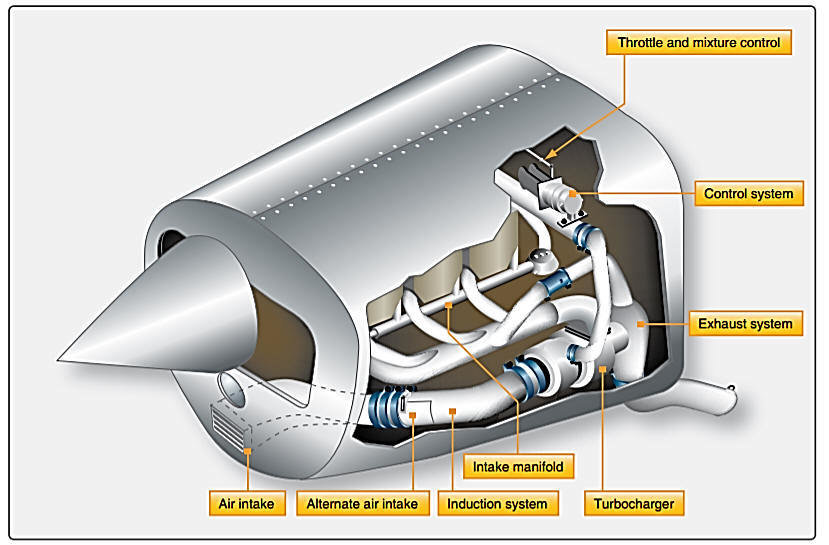
- To counteract this possibility, most aircraft are equipped with an alternate source of air that brings warm, unfiltered air from to the engine.
Induction System
Turbocharging Systems
The Maximum power an engine can produce is determined by the engine's RPMs and the air density.
Compressing the air that is entering a turbocharged engine allows the aircraft to develop more power and more power at higher altitudes can result in the following:
- Greater True Airspeed
- Less Atmosphere Aerodynamic resistance (Drag)
- Gives the pilot the possibility to circumnavigate adverse weather more easily
Turbocharger Diagram
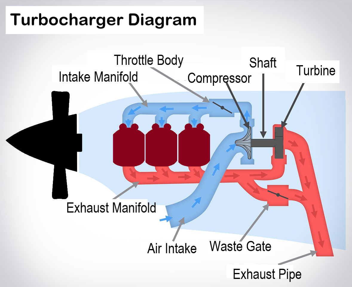
Turbocharging Principles
- The amount of power an engine can produce is dependent on the density of the air entering the engine.
- A turbocharged system will increase the air density regardless of the current atmospheric conditions.
- The system gathers energy produced by the combustion process to drive the turbine that will compress the air at higher altitudes. Increasing the power produced by the engine.
System Operation
Components of a Turbocharger
Turbocharged Aircraft have 4 main components:
Turbine
- The turbine is driven by exhaust gases exiting the engine.
- As the gases exit the engine through the exhaust manifold, they also pass the turbine. These gases traveling at high speeds and energy spin the turbine.
- The greater the power the engine is creating, the more exhaust gases it produces and the faster the turbine spins.
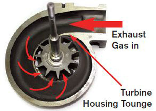
Turbine
Shaft
- When the engine is started, the turbine starts spinning. The torque it creates is transmitted to the compressor through the shaft, causing the compressor to start spinning as well.
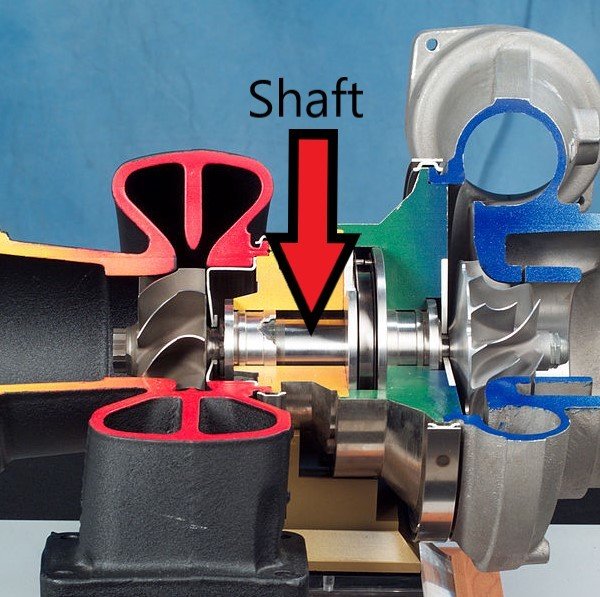
Shaft Diagram
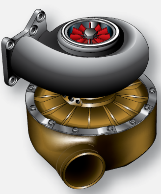
Compressor
- The compressor draws air from the outside. Its made of aluminum alloy spinning blades that compress the air and send it to the engine.
- This compressed-air has the same air density found at sea level, while the aircraft is operating at high altitudes. That's the advantage created by turbocharged systems.
Compressor
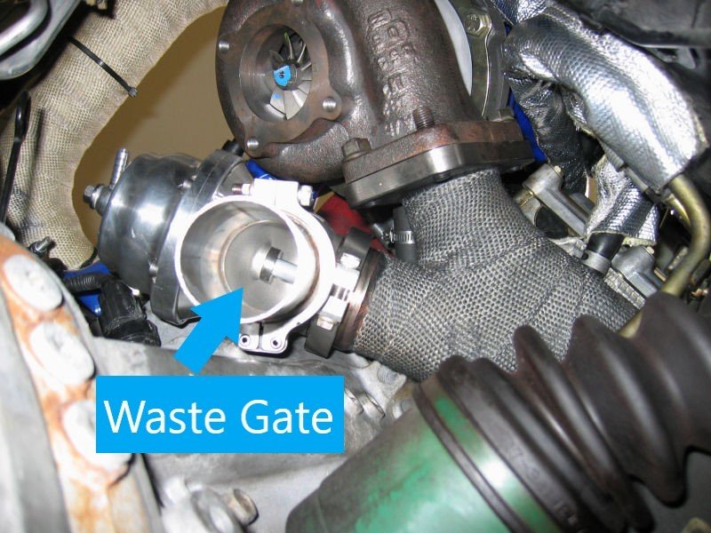
Waste Gate
- Turbocharged systems are capable of over compressing the air, and the manifold pressure produced, in some cases, may damage the engine.
- To prevent this from happening, the system is equipped with an automatic or manual (operated by the pilot) wastegate that opens and closes to regulate the amount of gas that passes over the turbine, to prevent it from spinning excessively and in turn damaging the engine.
Waste Gate
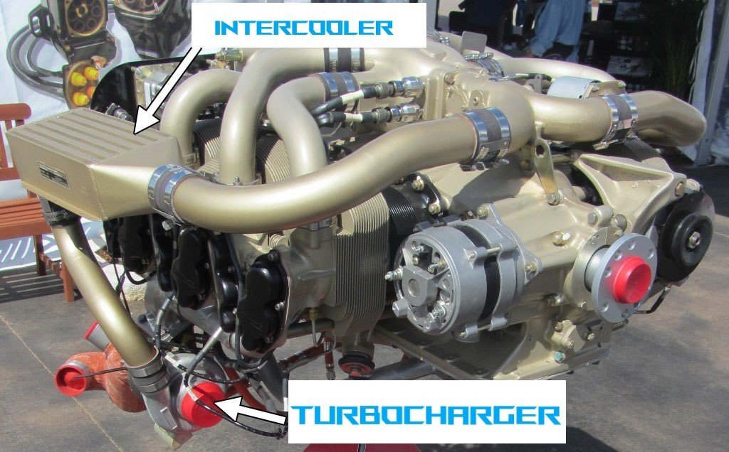
Intercooler
- As the air is compressed, it is heated up, and since the engine is already operating at hot temperatures, this unnecessary heat needs to be eliminated.
- To accomplish this, a mini air conditioning system is installed between the engine and the turbo. Its purpose is to cool the air before it reaches the engine.
Intercooler
High Altitude Performance
Turbocharger Critical Altitude
- Eventually, the engine reaches an altitude at which the compressor is unable to maintain the air at sea level. pressure. This altitude is referred to as critical altitude.
- The Critical altitude is the highest altitude where the engine can produce it's maximum horsepower.
Constant Speed Propeller
Diagram
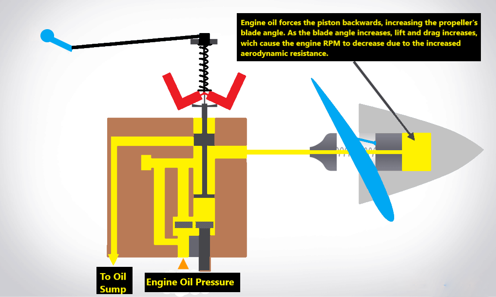
- A constant-speed propeller works by changing the pitch angle of the propeller blades.
- The higher the angle, the greater the amount of lift being produced (thrust), and at the same time, the greater the drag produced, causing the engine to produce more torque to spin the prop, which slows the engine down.
- When the angle decreases, less thurst is produced, and also less torque required so the engine speed up.
Propeller Principles
Constant Speed Meaning
- A constant-speed propeller allows you to increase propeller efficiency in every phase of flight, allowing you to control its speed in different scenarios to obtain the most significant power or the highest fuel efficiency out of the engine.
- On takeoff, you want to select high RPMs to obtain the most amount of power from your engine.
- While cruising, you can pull the RPM back by increasing the blade angle, making your engine more fuel-efficient.
Components
The propeller changes its blade angle by redirecting the same engine oil used for engine lubrication to hydraulically change the propeller pitch. The following components are used as part of the system.
Governor
- The governor is in charge of moving oil through the propeller hub. This will adjust the angle of the propeller blades in order to achieve the RPM's desired by the pilot.
Propeller Control
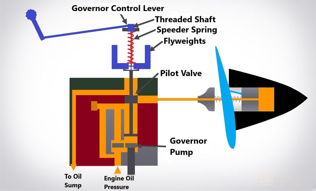
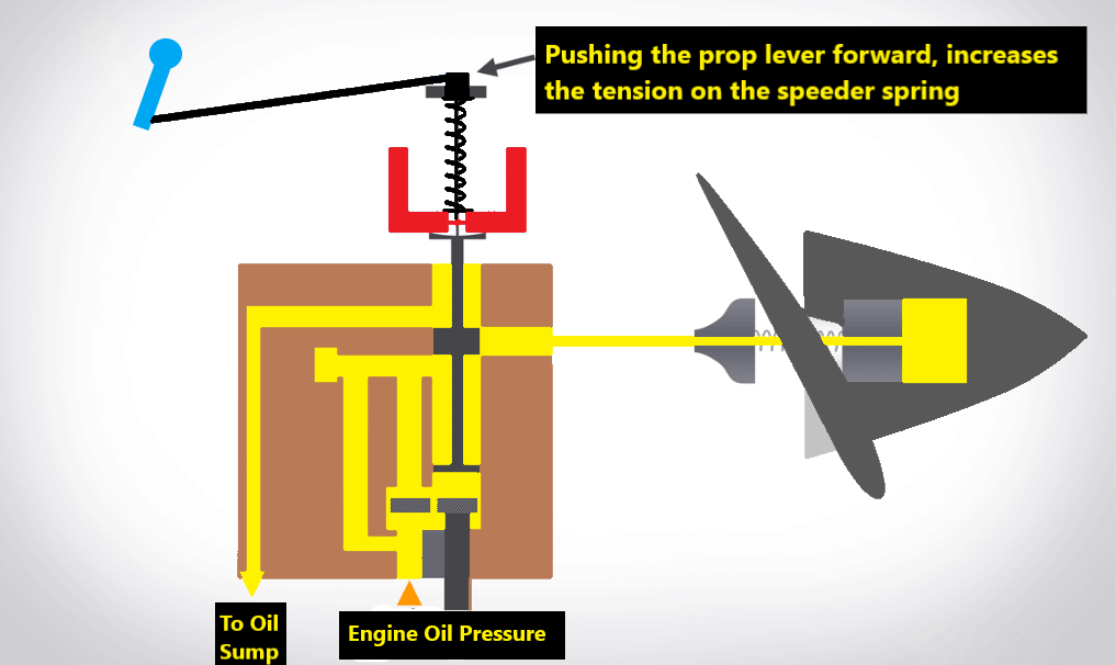
- The propeller control in the cockpit is attached with the governor control lever thought a mechanical linkage.
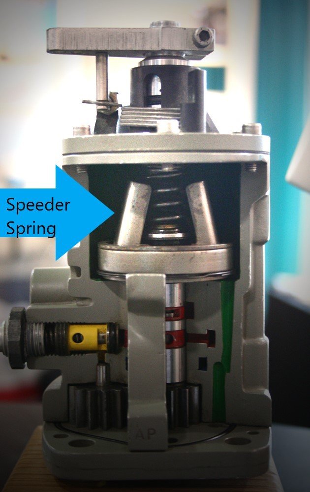
- Moving the prop control forward, increases pressure in the speeder spring, pushing it back decreases the pressure exerted in the speeder spring.
Propeller Control

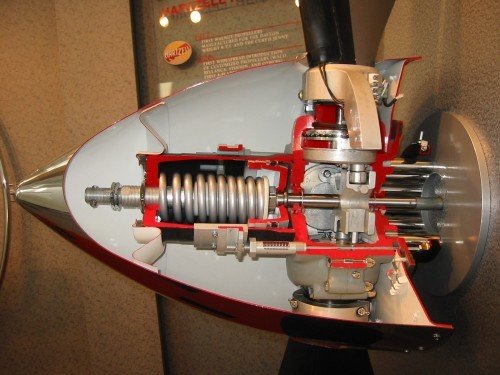
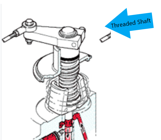
Threaded Shaft
-
The threaded shaft is connected to the governor control lever. When it turns left, it moves up, and when it turns right, it moves down. Increasing or decreasing the pressure exerted on the speeder spring.
Threaded Shaft
Speeder Sping
- The speeder spring is located between the threaded shaft and the flyweights. When the threaded shaft moves down, the tension in the speeder spring increases, when it moves up, this tension is released. This either forces the flyweights inward or outward.
Speeder Spring
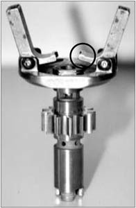
Flyweights
Flyweights
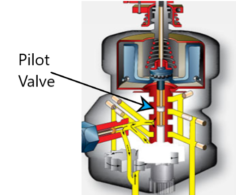
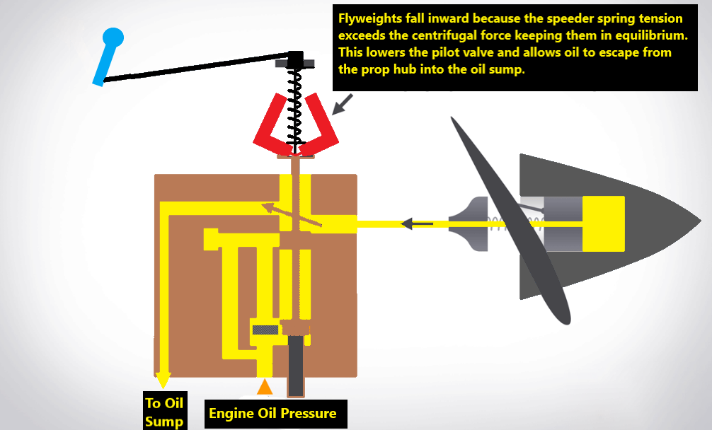
Pilot Valve
-
The pilot valve is connected to the flyweights. It is moved upward and downward by the flyweights, allowing oil to flow into, or out of, the propeller hub.
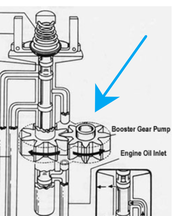
Governor Gear Pump
-
The pump boosts oil pressure before it heads out of the governor and into the propeller hub. With the increase in pressure, the propeller can change its pitch easily with the movement of the propeller control in the cockpit.
Constant Speed Propeller Operation
1
2
3
4
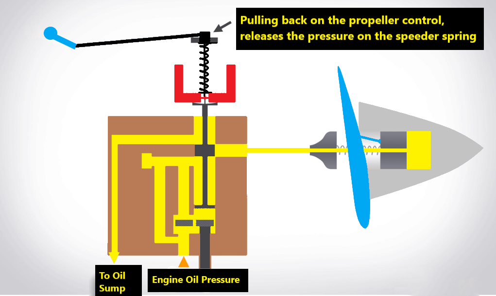
Prop Lever Moves Backwards
Prop Lever Forward Movement
1
2
3
4
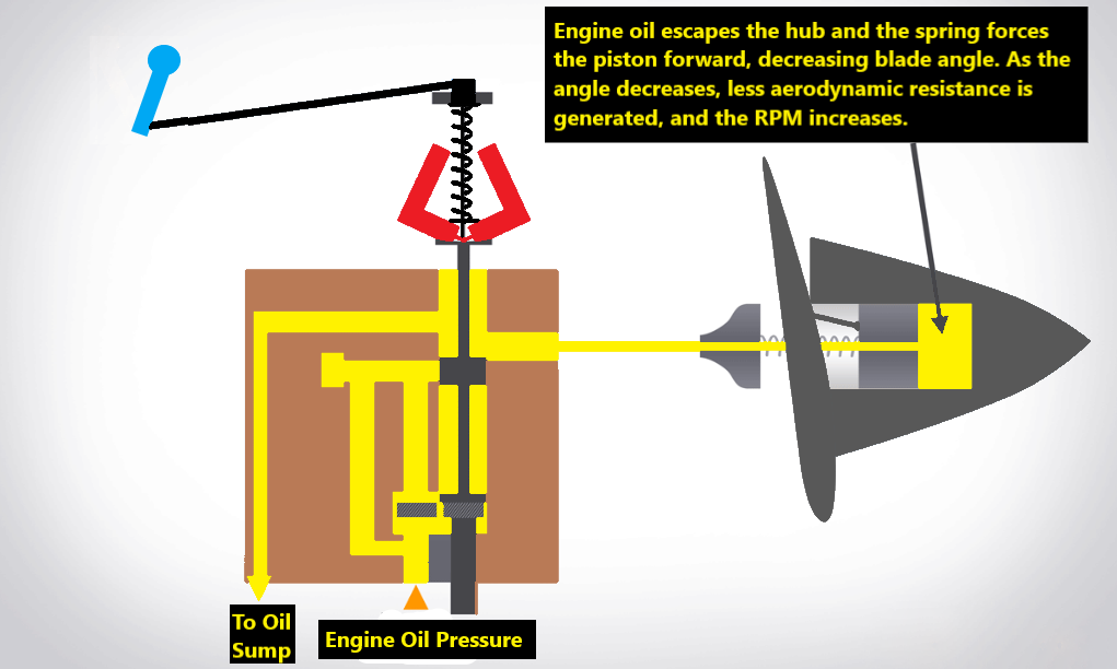
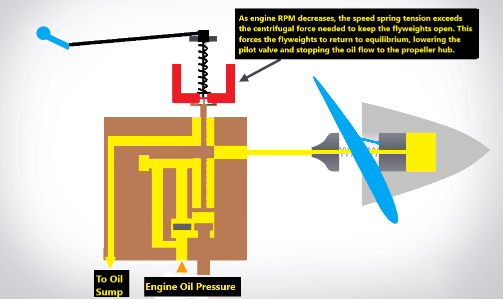
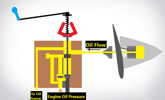
Underspeed
- When a complex airplane pitches up, drag increases. For a constant speed propeller to keep a constant RPM setting, the governor must react. The increase in drag will cause the engine to work harder, which will slow it down.
- The decrease in engine torque will also cause a decrease in centrifugal force which will cause the speeder spring tension to make the flyweights fall inward. The pilot valve will move down, and oil will flow out of the propeller hub, reducing the pitch of the blades.
Underspeed
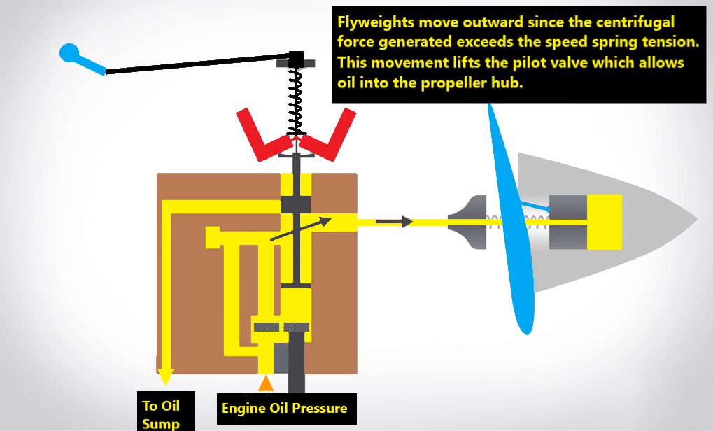
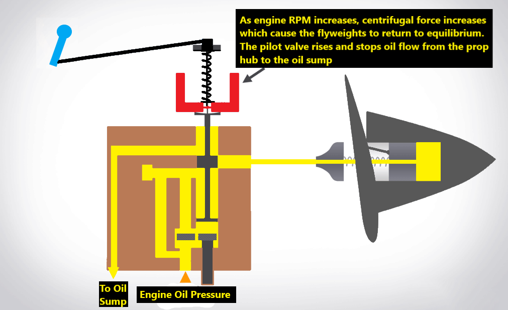
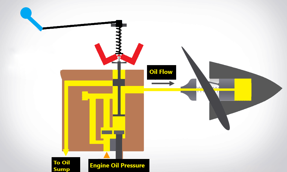
Overspeed
- When the airplane pitches down, there's less drag resistance, and the engine speeds up. When this happens, the increase in centrifugal force generated by the engine will overcome the speeder spring tension.
- As a result, the flyweights fly outward, and the pilot valve rises. This allows oil into the prop hub, which will increase the propeller blade angle, generating more resistance and slowing the engine down to the RPM value selected.
Overspeed
Power Controls
- On airplanes equipped with a constants speed propeller, engine power is controlled by the throttle (black lever) and indicated on the manifold pressure gauge.
- The propeller control (blue lever), controls the propeller blade angle which in turn regulates the engine's RPM gauge.
- The configuration of these two levers will vary depending on the flight condition (takeoff, landing, cruising, etc). Generally, when increasing RPMs, the prop control is adjusted first, followed by the throttle. When decreasing power the throttle is adjusted first followed by the prop control.
FADEC
FADEC (Full Authority Digital Engine Control) is a computerized system that optimizes engine and propeller performance by automatically adjusting fuel injection, eliminating the need for magnetos and mixture controls. It simplifies engine operation with a single power lever but requires redundant control units and backup power to prevent engine failure. Regular preflight checks ensure system reliability.