GL 2.3 Advance Systems Retractable Landing Gear

Disclaimer
Students should use their textbooks, syllabus, and Airman Certification Standards (ACS) as their primary sources of information. EcFlight is an online training tool designed to simplify and enhance your ground school learning experience. However, it is not a substitute for FAA- or school-approved study materials. Before using these slides for study, always refer to your officially approved resources, such as the Jeppesen physical or electronic book and other FAA-approved materials.
Reference Books
- Arrow PA-28R-201: Information Manual. Piper Aircraft Corporation, 2001.
- Federal Aviation Administration (FAA)/Aviation Supplies & Academics (ASA). Aviation Maintenance Technician Handbook: Airframe, Volume 2: FAA-H-8083-31A, Volume 2. Aviation Supplies & Academics, Inc., 2018.
Reference Media
-
Image by <a href="https://pixabay.com/users/annca-1564471/?utm_source=linkattribution&utm_medium=referral&utm_campaign=image&utm_content=1
-
Image by <a href="https://pixabay.com/users/dayamay-7372173/?utm_source=linkattribution&utm_medium=referral&utm_campaign=image&utm_content=47
-
https://pixabay.com/vectors/plane-landing-gear-airplane-wheel-34036/
-
https://pixabay.com/photos/fighter-plane-history-undercarriage-4702458/
Index
Hydraulic Gear Systems
Airspeed Limitations
Gear System Operation
Landing Gear Safety Switches & Relief Valves
Landing Gear Malfuctions
Landing Gear Systems
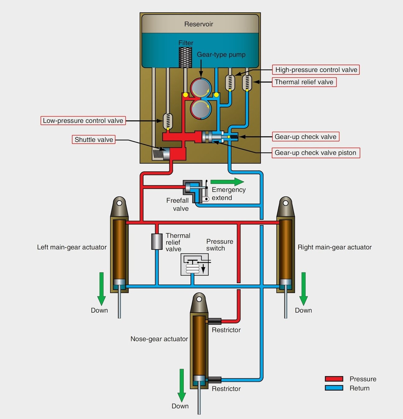
Hydraulic Gear System
- Either an electrical or engine driven pump is used to pump the fluid around the system. The hydraulic fluid is redirected to a reservoir that stores the excess fluid.
-
Some aircraft use a hydraulic gear system to raise and lower the gear. When the gear is retracted, pressurized hydraulic fluid flows though a series of up or down lines to the acuating cylinders which either retracts or extends the gear.
Hydraulic Landing Gear
Landing Gear Switches & Relief Valves

Gear Switches
Gear Relief Valves
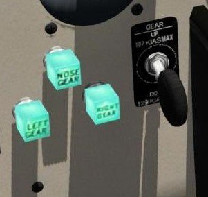
Gear Control Lever
- The gear control lever will turn on the hydraulic pump any time the pilot wants to retract or extend the gear. The gear selector switch is located to the left of the control quadrant.
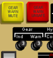
- A RED WARNING GEAR UNSAFE light, located at the top of the panel,illuminates while the gear is in transit, or not in the full up or locked down position.
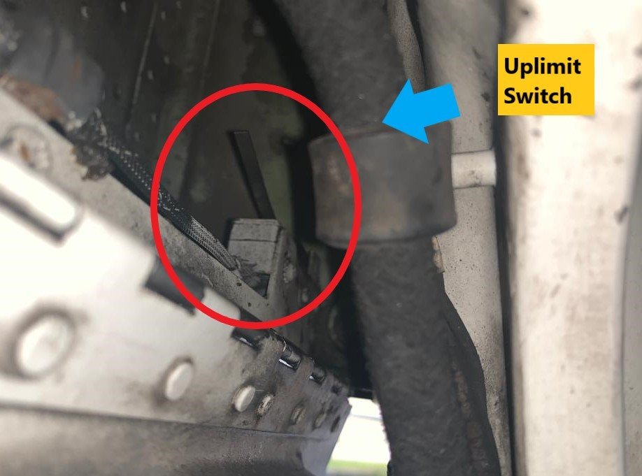
Uplimit Switches
- There are a total of three uplimit switches on the system. Each gear has its respective switch. When each gear is up and locked they will close each individual switch. Once the three switches are closed the gear unsafe light will turn off.
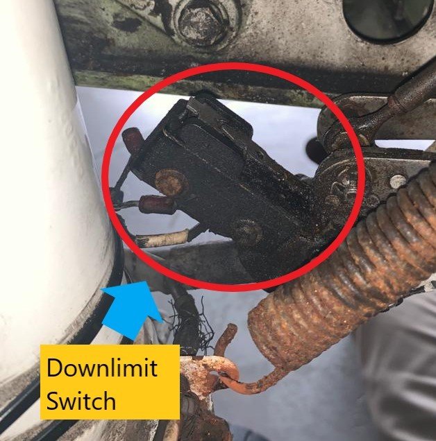
Downlimit Switches
- There are a total of three downlimit switches on the system. Each gear has its respective switch. When each gear is down and locked they will achieve 3 functions:
2
1
3
They will turn on the 3 green lights, indicating the gear is down and locked.
When all three switches are closed, the hydraulic pump will turn off.
When all three switches are closed, the gear unsafe light will turn off.
Downlimit Swtich
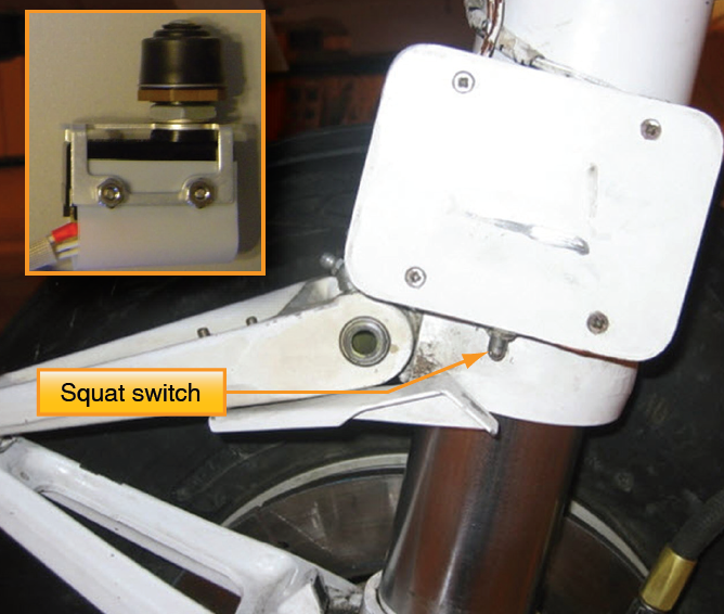
Squat Switch
- The squat switch is located on the left main gear. When the aircraft is on the ground, it will feel the weight of the plane and deactivate the electric path between the gear control lever and the hydraulic pump. This will prevent the gear from retracting when the lever is pushed up while on the ground.
Pressure Switch
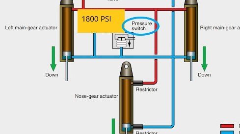
- The pressure switch will turn off the pump as soon as the pressure reaches 1800 PSI, once the gear is up and locked.
Throttle Switch
- Any time the throttle is brought below 14 inHg and the gear is still retracted, the GEAR UNSAFE LIGHT will illuminate, and a horn will emit a beeping sound. This is a visual and auditive warning that reminds the pilot to lower the gear when setting up for landing.
Flap Switch
- Any time flaps 25° or 40° are selected while the gear is still retracted, the GEAR UNSAFE LIGHT will illuminate, and a horn will emit a beeping sound. This is a visual and auditive warning that reminds the pilot to lower the gear when setting up for landing.
High Pressure Relief Valve
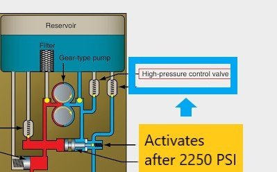
- The high pressure relief valve will sense if the pressure would exceed 2,250 PSI on gear retraction. If the pressure exceeds this value some of the hydraulic fluid returns back to the reservoir preventing overpressurizing the lines.
Low Pressure Relief Valve
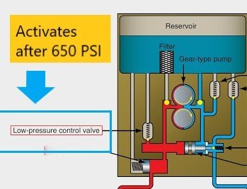
- The low-pressure relief valve will sense if the pressure would exceed 650 PSI on gear extension. If the pressure exceeds this value some of the hydraulic fluid returns back to the reservoir preventing overpressurizing the lines.
Thermal Relief Valve
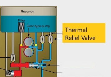
- The thermal relief valve will send some of the fluid back to the reservoir if the temperature where to increase beyond acceptable values inside the lines. This will prevent the expansion of the fluid from overpressuring the lines when the gear is retracted.
Emergency Extension Valve
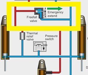
- The Emergency extension valve will allow fluid to return to the reservoir allowing the gear to freefall in the event of a hydraulic pump malfunction or a hydraulic leak.
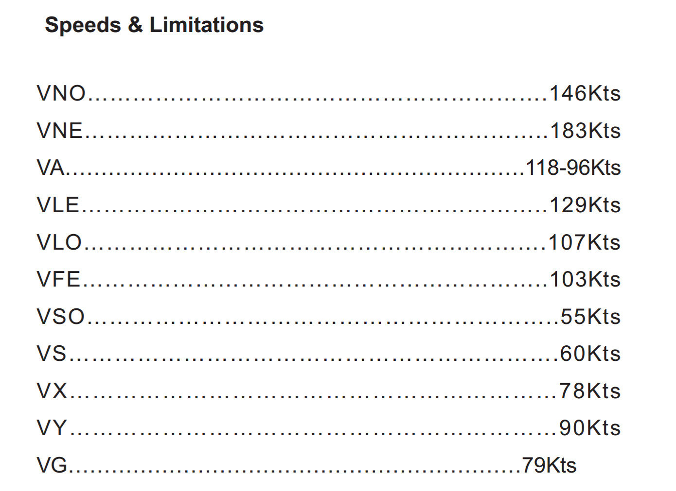
Airspeed Limitations
Landing Gear Vspeeds
- VLe: Maximum Landing Gear Extended Speed. When extending the gear during landing, airspeed should be reduced below 129 KIAS according to the PA-28R-201 Operating Handbook.
- VLo: Maximum landing gear operating speed. When retracting the gear during takeoff or while performing maneuvers, it should be done at a speed of no more than 107 KIAS according to the PA-28-201.
Arrow V Speeds
Gear system operation
Landing Gear Extension
Landing Gear Retraction
Landing Gear Malfunctions
Landing Gear Position Lights do not illuminate
- If one or none of the 3 green lights come on during gear extension, verify the following elements:
1
2
Verify NAV Lights are off during daytime.
Switch between green bulbs. One of them may have burned out.
3
Check hydraulic pump and landing gear lights circuit breakers.
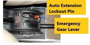
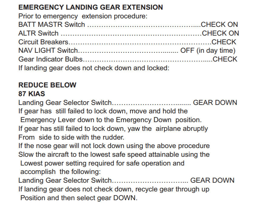
Emergency Gear Extension
- In the event the gear is believed to be in an unsafe position for landing. Do not hesitate in using the emergency gear extension procedure and thoroughly follow the corresponding checklist.
Animation