GL 12 Approach Chart

Rev 02/2025
Disclaimer
Students should use their textbooks, syllabus, and Airman Certification Standards (ACS) as their primary sources of information. EcFlight is an online training tool designed to simplify and enhance your ground school learning experience. However, it is not a substitute for FAA- or school-approved study materials. Before using these slides for study, always refer to your officially approved resources, such as the Jeppesen physical or electronic book and other FAA-approved materials.
Reference Books
-
Instrument Flying Handbook FAA-H-8083-15B. Skyhorse Publ., 2013.
-
Instrument Procedures Handbook (Federal Aviation Administration): FAA-H-8083-16A. Skyhorse Publishing, 2017.
Reference Multimedia
- “Digital - Terminal Procedures Publication (d-TPP)/Airport Diagrams.” FAA Seal, 2 Apr. 2020, www.faa.gov/air_traffic/flight_info/aeronav/digital_products/dtpp/.
Index

Approach Considerations
Approach Procedure
Types
- Instrument approaches are classified in three types of approach procedures.
- They are based on the final approach course guidance and primary navigation system.
Precision
- Provides lateral and vertical guidance and meets the requirements of ICAO Annex 10
Non - Precision
- Provides only lateral guidance
APV
- Provides vertical and lateral guidance but doesn't meet the requirements to be considered a precision approach
Transition from Enroute to Approach
- First, we have to understand what an approach segment is.
- There are different methods that will smoothen the transition from the enroute structure to the initial approach segment.
An instrument approach procedure includes the following segments:
- Enroute Segment
- Initial Approach Segment
- Intermediate Approach Segment
- Final Approach Segment
- Missed Approach Segment
Approach Segments
Enroute Segment
- Starts from an enroute fix (navaid, fix, waypoint, etc) on an airway or an arrival and ends up in an IAF.
- Also refered to as feeder route, which will provide the same obstacle clearance as an airway.
- Its identified by a solid black line with a distance, MEA, and direction.
- Provides transtion from the enroute to the approach structure of an IFR flight.
Feeder Route
Initial Approach Segment
- Connects the IAF (Initial Approach Fix) with the IF (Intermediate Fix) or Point and allows preparation for the final descent to land.
- Its purpose is to align the aircraft with the intermediate segment.
- Provides an obstacle clearance of 1,000 feet in both mountainous and non-mountainous terrain.
- The letters IAF indicate the location of the initial approach fix. There might be several IAF on a single approach.
Initial Approach Segment
Intermediate Approach Segment
- It blends the initial approach segment into the final approach segment allowing the aircraft to be align generally within 30 degrees of the final approach course.
-
Goes from the IF to the FAF .
- It allows the pilot to get configured for landing.
- If the approach doesn't include a IF. The intermediate segments starts when the aircraft is preceding inbound to the FAF.
Intermediate Segment
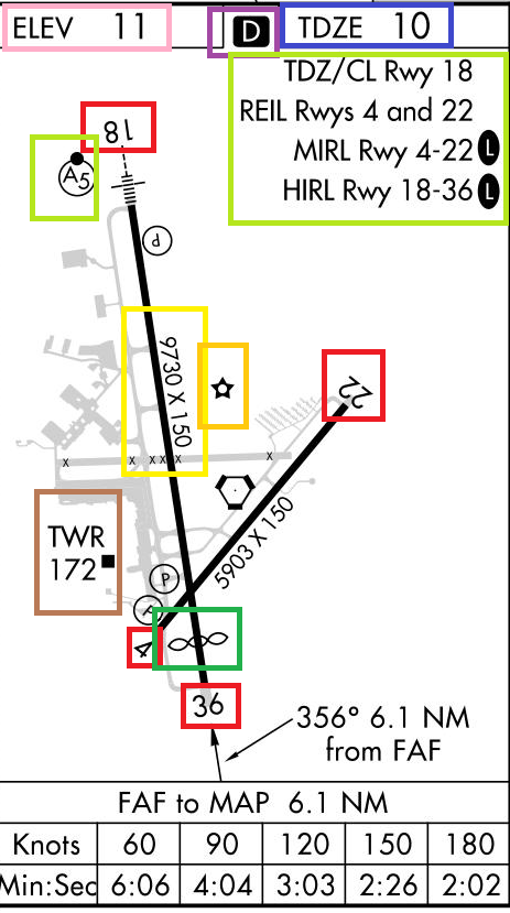
Final Approach Segment
- The final approach segment begins at the FAF or FAP and ends in the MAP.
- The final approach fix is generally identified with a maltese cross for non-precision approaches and a lightning bolt for every approach with vertical guidance.
- This segment is where the pilot decides if they have the required visual reference for landing or if they have to perform a missed approach.
Final Approach Segment
Missed Approach Segment
- The missed approach segment goes from the MAP (Missed Approach Point) to the point where you either attempt another approach or continue to your alternate.
- For Non - Precision approaches the MAP can be a fix, navaid, or elapsed time upon crossing the FAF.
- For precision approaches the MAP segment begins upon reaching DA (Decision Altitude), if the descent requirements have not been met.
- It generally includes a holding pattern that ends in an enroute fix or an IAF fix.
Missed Approach Segment
Runway and Approach Lighting
- Runway and approach lights help transition from instrument to visual flight when approaching the airport.
- Approach lighting systems starts at the landing threshold and extend into the approach area.
-
Precision Approaches
- lights extend 2,400 to 3,000 ft
Types of Approach Lighting System
-
Non precision Approaches
- lights may only extend 1,400 to 1,500 ft

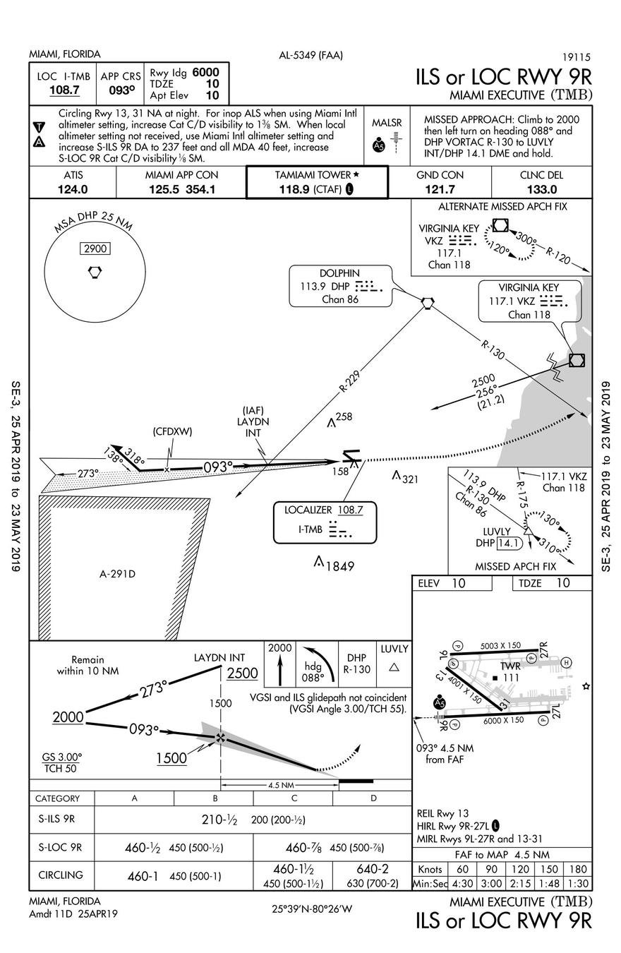
Approach Charts
Chart Layout
There are two instrument approach charts format available:
- Jeppesen
- FAA (Terminal Procedures Publications (TPPs)
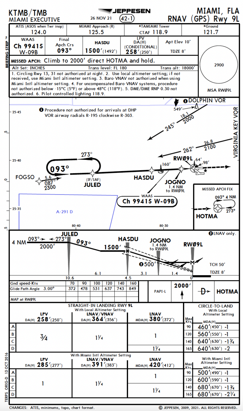
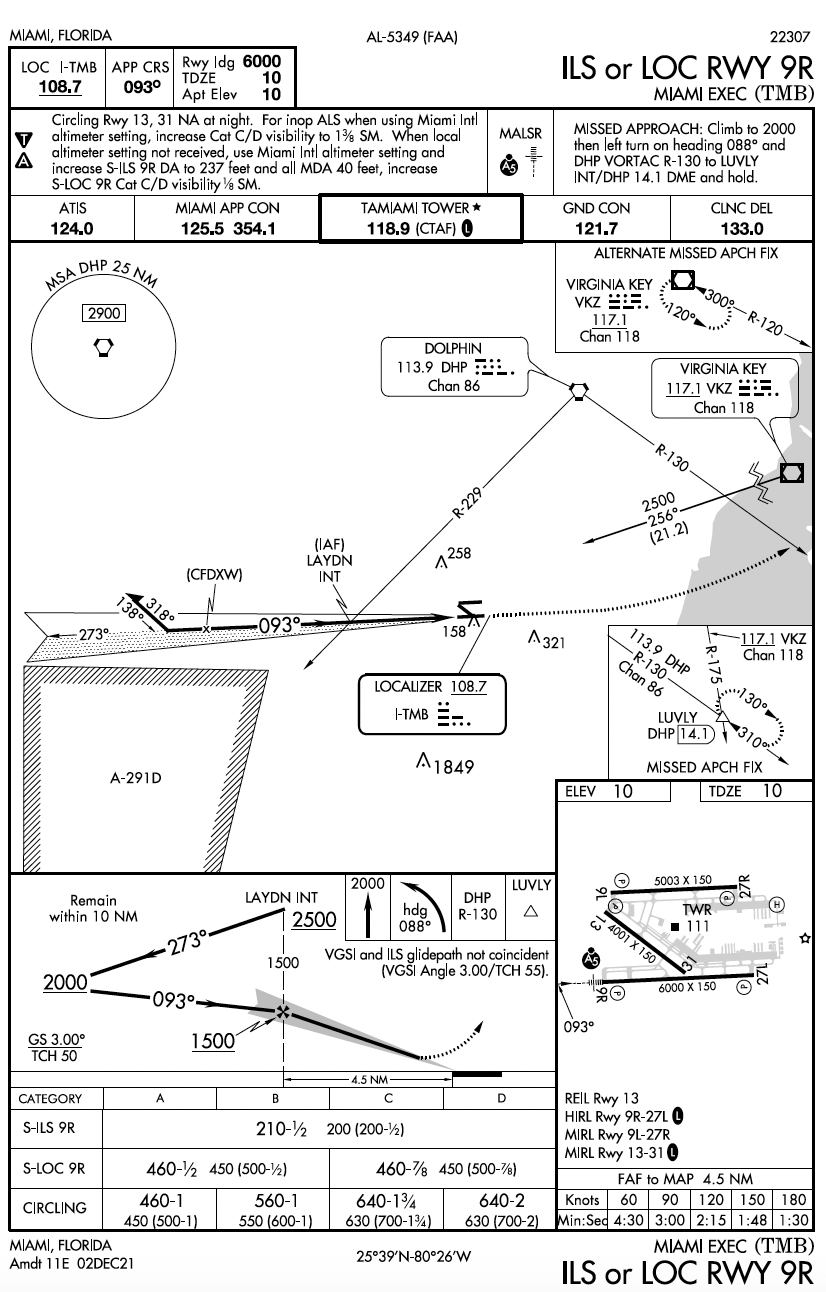
Both formats provide the same information such as:
- Heading Section
- Communication Section
- Approach Briefing
- Minimum Safe Altitude (MSA)
- Plan View
- Profile View
- Descent/Timing Conversion Table
- Lighting Bpx
- Missed Approach Icons
- Landing Minimum Section
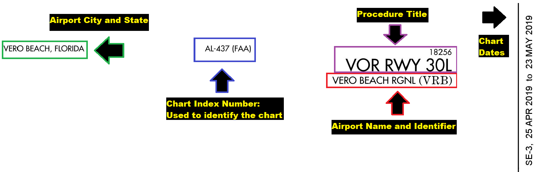
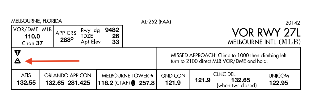
Heading Section
- Used to determine if the chart is current or not.
- Identifies city, airport, instrument approach procedure tittle, and airport ICAO identifier.
- The procedure title is used to show us what minimum equipment is required to fly the Final Segment of the approach. (Ex: VOR\DME receiver, ILS receiver, etc.)
- The chart index number is used to identify the city and procedure type when similar approaches exist in the area.
Heading Section
Communication Section
- Communications are listed in the order pilots generally use them.
- ATIS frequency is used to get the weather at the destination airport.
- Approach Frequencies are used to make vfr and ifr approach requests.
- Part time facilities are identified with a star and pilots should refer to the chart supplement to find more about them.
Communication Section

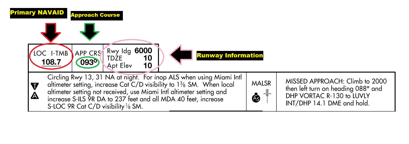
Briefing Information
- Primary Nav Information: Identifies the NAVAID type and frequency used to fly the approach.
- Approach Course: Shows the course used when flying the final approach Segment.
- Runway Information: Shows airport runway and elevation data.
Briefing Section
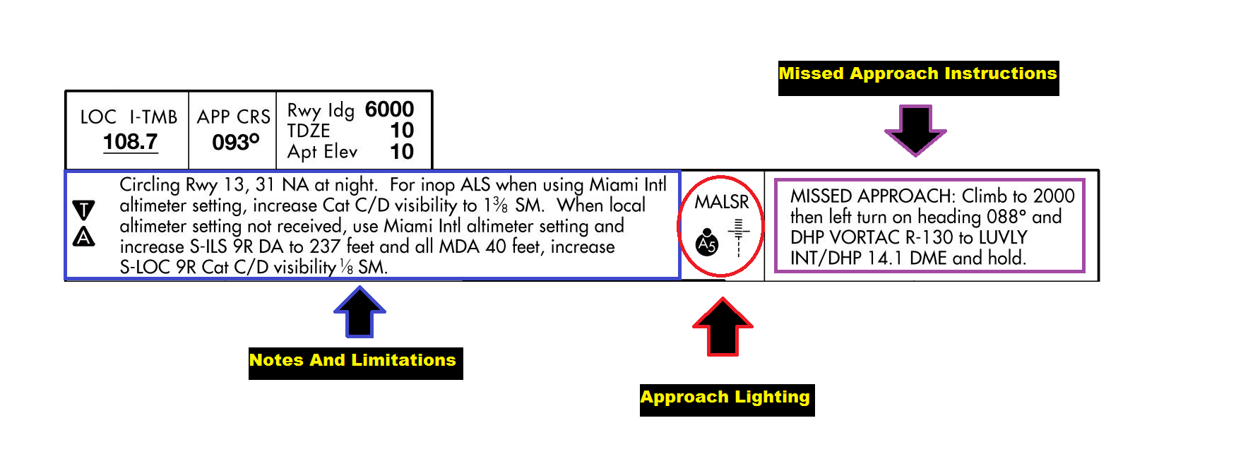
- Notes and Limitations: Provides takeoff and landing limitations when conducting the approach with inoperative equipment.
- Approach Lighting: Identifies which type of lightning is available for the approach.
- Missed Approach Instructions: Provides the instruction of what ATC expects the pilot to do in the event of a missed approach.
Briefing Section
Minimum Safe/Sector Altitude (MSA)
- The MSA provides 1000 feet of obstacle clearance within 25 NM of the facility indicated on the chart.
- Navigation or communication coverage is not guaranteed.
- It's only meant to be used during an emergency on an IFR flight or during VFR at night if the pilot is unfamiliar with the surrounding terrain.
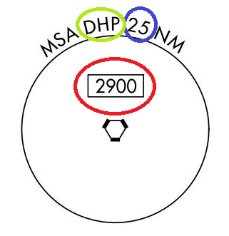
Minimum Safe Altitude
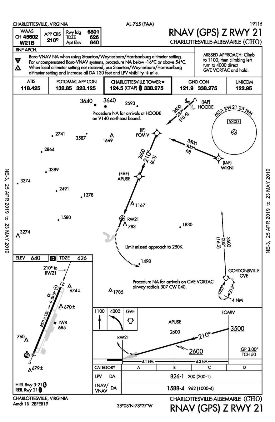
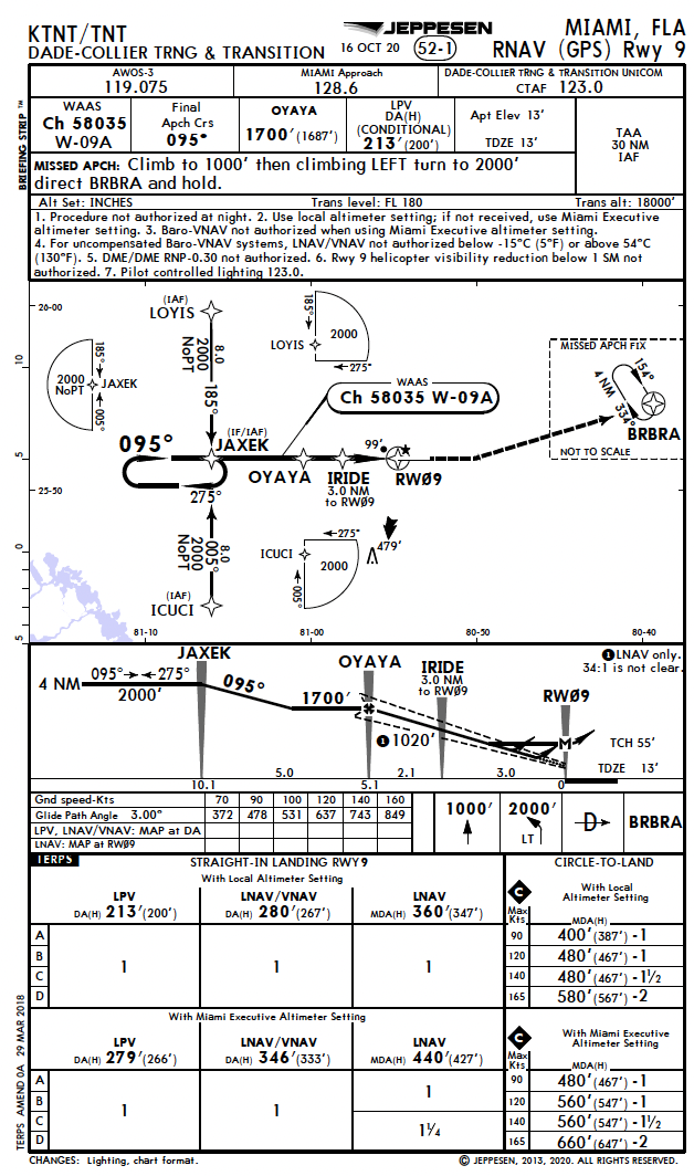
Terminal Arrival Altitude (TAA)
Terminal Arrival Altitude (TAA) is the lowest altitude that provides a minimum clearance of 300 m (1,000 ft) above all objects located in a 25 NM radius centered on the initial approach fix (IAF) or intermediate approach fix (IF) if there's no IAF.
Terminal Arrival Area (TAA)
- There are instrument procedures that uses terminal arrival areas (TAA) that provides a continues transition from the enroute to the terminal area using RNAV equipment.
- On Jeppesen charts, the MSA is replaced with a reference to the TAA 30 NM boundary within the IAF.
TAA
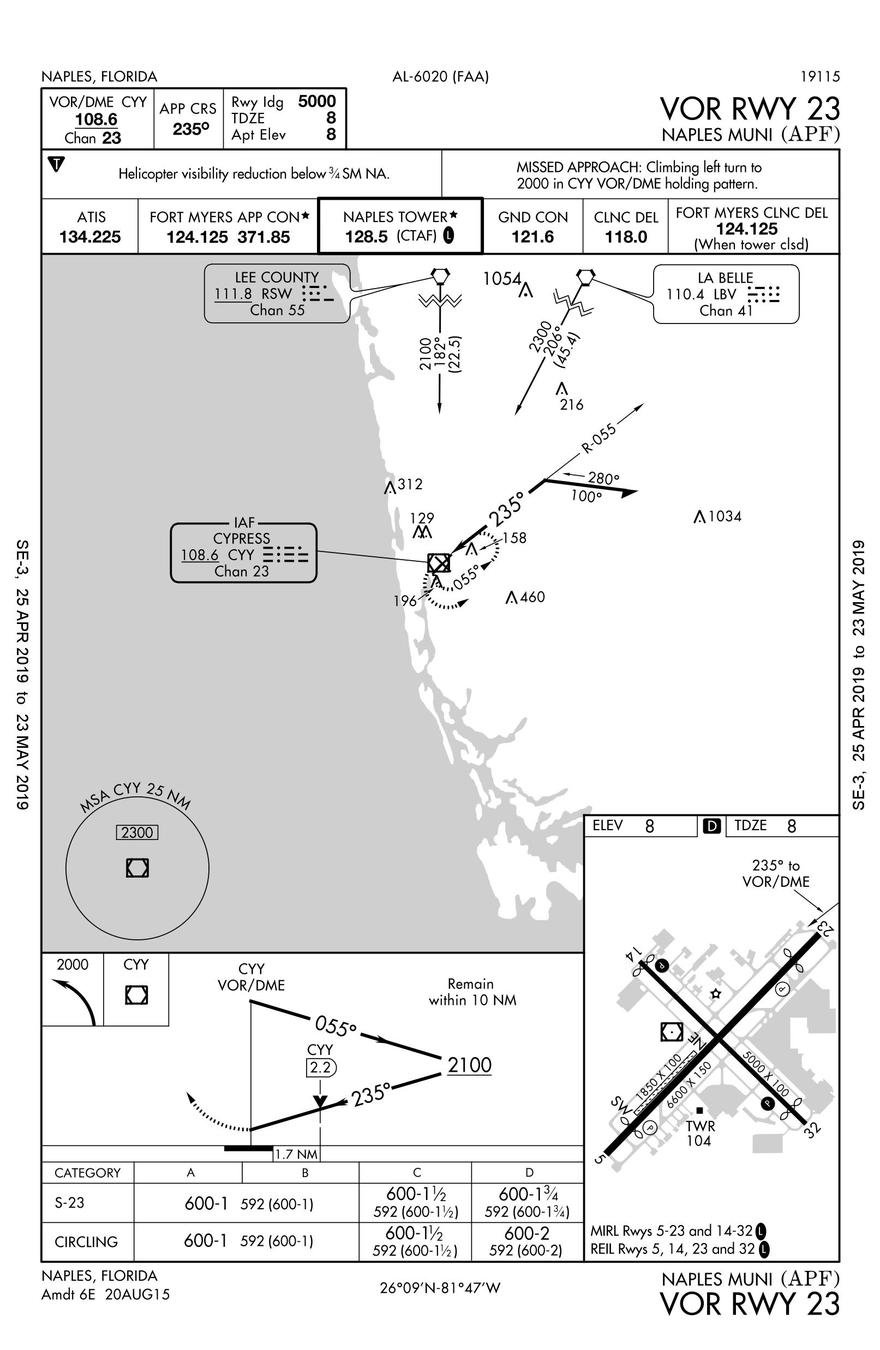
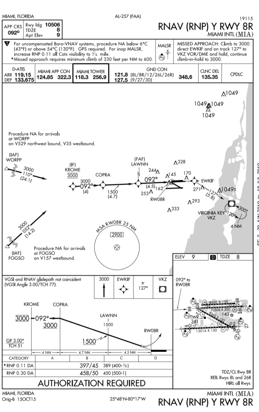
Plan View
"The plan view allows you to view the approach from the top. It will help the pilot identify his position on the approach (situational awareness), and any high terrain or obstacles. "
-
Primary Navigational Aid: Identifies the name or type, frequency, identifier, and identifier morse code of the navaid used to track the approach course.
- Feeder Route: Thick black lines identify the enourte segment of the approach or feeder route.
- Initial Approach Fixes: The letters IAF identify the different ways to join the initial approach segment on an specifc approach.
Plan View
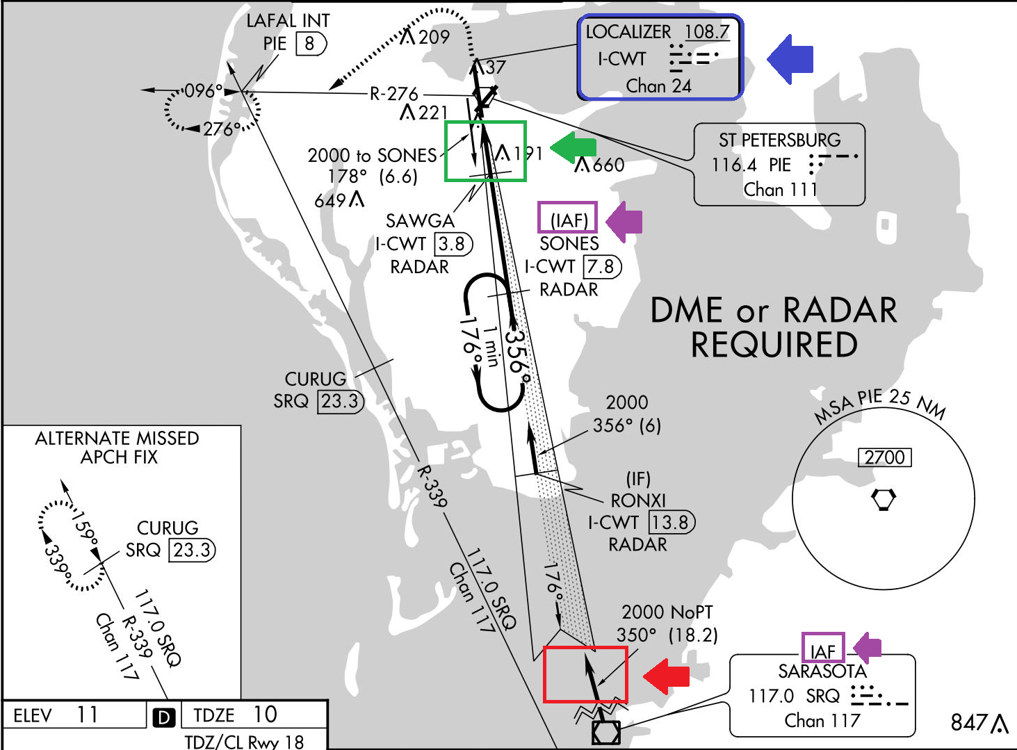
- Non flyable radials: This radials are only used to identify different fixes on the approach.
- Lead In Radial: If performing a dme arc as part on the initial segment of an instrument approach. The lead in radial will help the pilot to anticipate the interception of the localizer signal.
- Missed approach track: The dashed line describes the missed approach track that generally takes you to a holding pattern that has also dashed lines.
- Outer Marker: Antenna transmitting an elliptical signal that is used to the identify the FAF of a non precision approach.
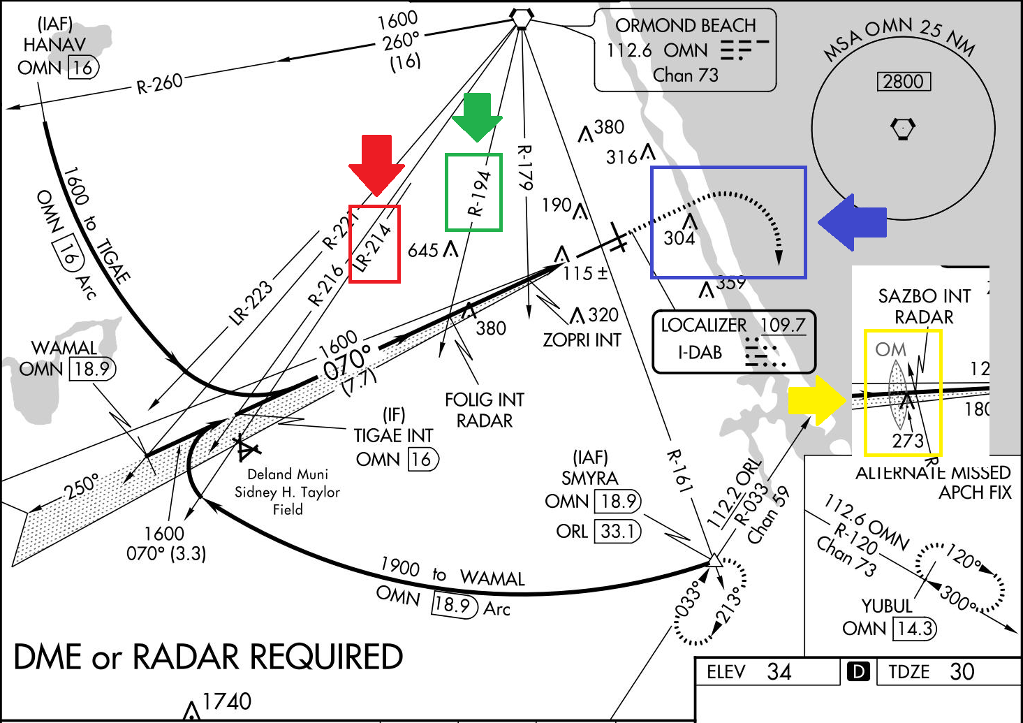
Plan View
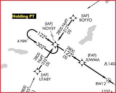
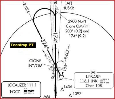
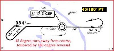
Course Reversal Depiction
- Depending on the angle you approach an airport. A procedure might become required in order for the aircraft to become aligned with the runway.
- A procedure turn (PT) can be done in a desire way as long as the pilot complies with the appropriate instructions on the profile view.
Holding PT
45/180° PT
Teardrop PT
Terrain and Obstacle Depiction
-
Only limited terrain and obstruction will be found on charts.
-
Obstacle clearance will be provided during the approach procedure.
- Terrain or structures less than 400 ft above airport elevation is NOT depicted on Jeppesen charts
FAA
Jeppesen
Highest terrain or obstacle is indicated by an arrow
Large triagle symbol with the elevation indicated shows the highest obstacle
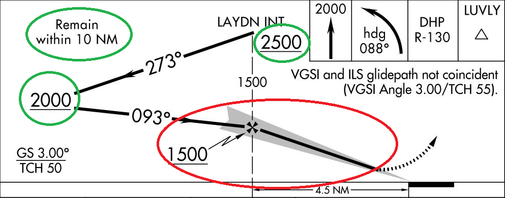
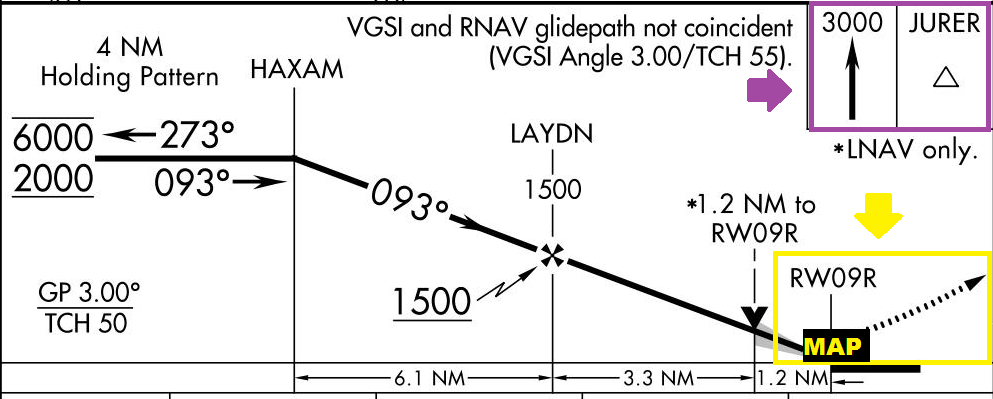
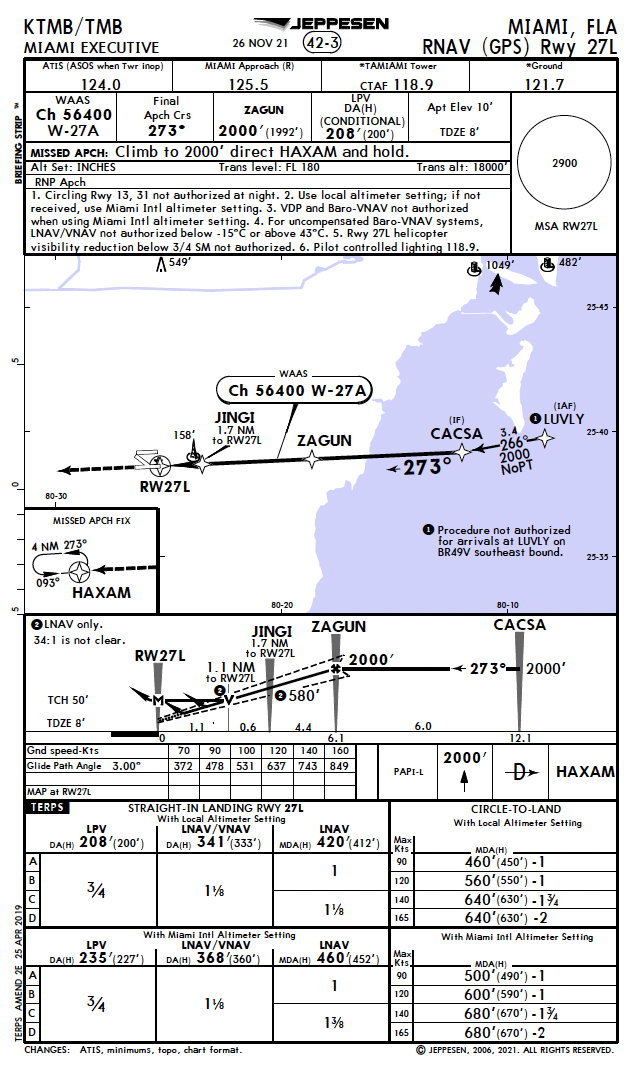
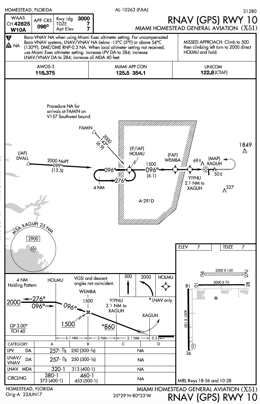
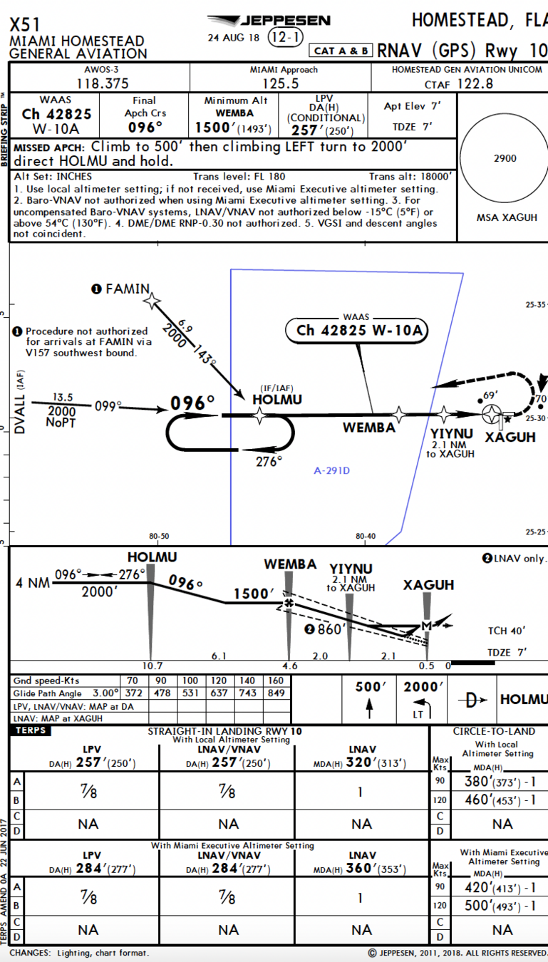
Profile View
"The profile view allow you to view the approach from a vertical dimension. It gives information regarding the course reversal, final and missed approach segment of the approach"
- Course Reversal: It provides information regarding the maximum distance pilots are allow to extend while performing the Procedure Turn and the minimum altitudes they should be at.
- Approach Path: The approach path shows the inbound course and the altitude pilots should descend after becoming established inbound.
Profile View
- Missed Approach Icons: Identify the initial instructions pilots should follow in the event of a missed approach .
- Missed Approach Depiction: A dotted line that extends at the end of the approach path identifies the missed approach action pilots should take upon reaching the MAP for precision, APV, and precision approaches. The MAP will always be part of the doted line.
Profile View
Jeppesen
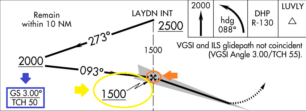
- Non Precision Approach FAF: A maltesse cross is used to identify the FAF for a non precesion approach. It can be identified by a radial, outer marker, or other dme fix.
- Glideslope Intercept Altitude: The lightening bolt identifies the certified glideslope intercept altitude (FAF for APV or precision APP). It is the point where the final segment begins on approaches with vertical guidance.
- Glide slope and Treshold Crossing Height: The TCH is the altitude at which you will cross the treshold if you keep the glideslope centered all the way towards landing.
Profile View
- Approach Distances: Distances between fixes on the approach path. This distances shouldn't be used as DME distance since is not slant range distance.
- DME FIXES: Dme fixes are made of a navaid identifier and the respective DME mileage to the station.
Profile View
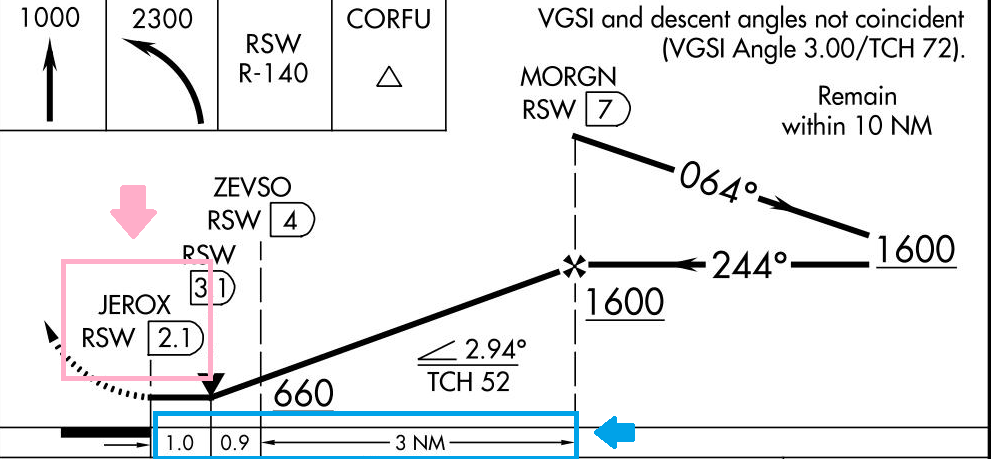
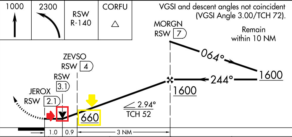
- Step Down Fixes: If performing an instrument approach there will be altitude restrictions in different fixes. Pilots must plan to cross this fixes at the specified altitudes.
- Visual Descent Point (HAT divided by 300feet) : It's a point in a non precision approach from which a descent below the MDA can be done providing the runway environment is in sight. If the VDP is crossed at the MDA the aircraft will be aligned with a visual descent aid.
Profile View
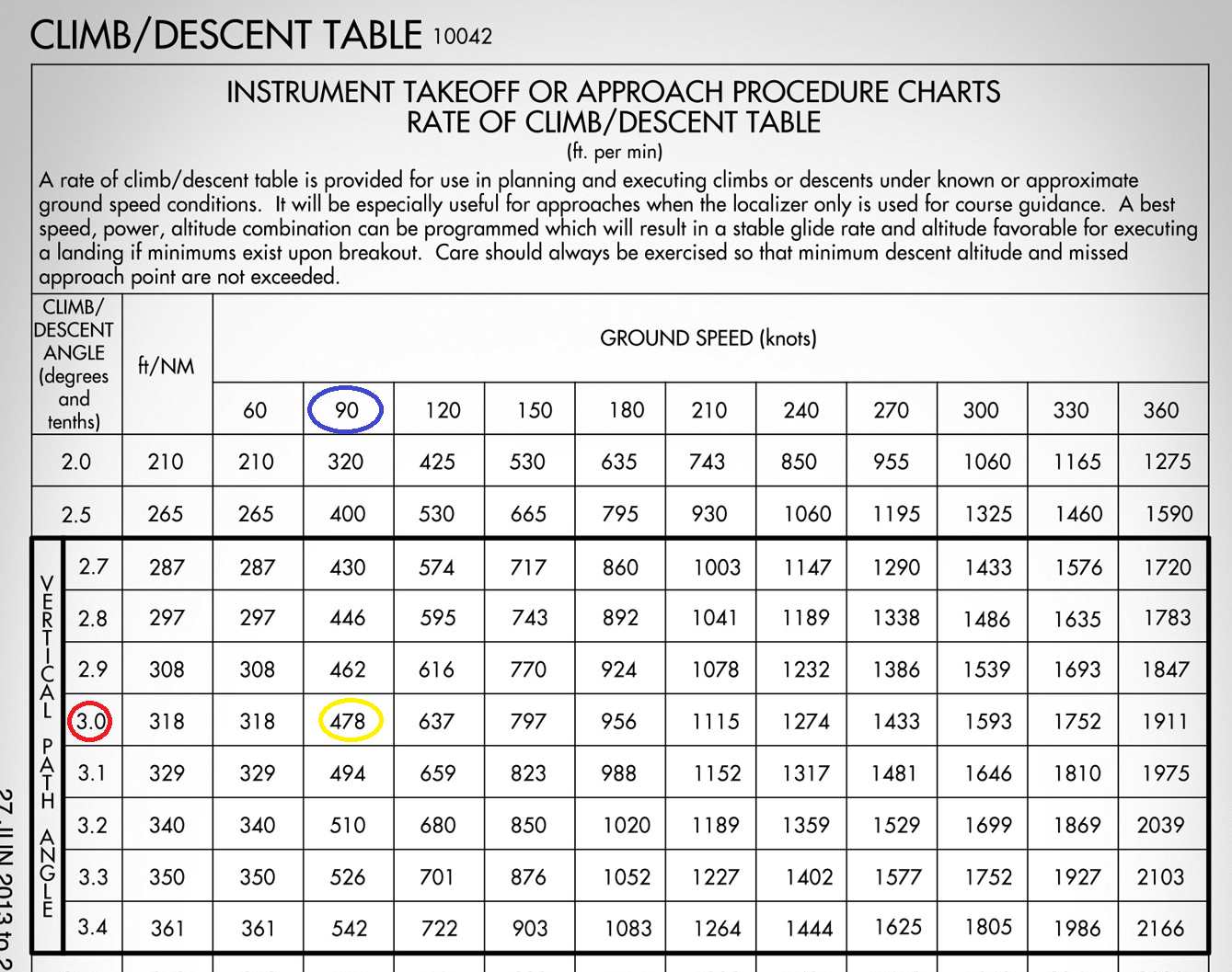
Descent/Timing Conversion Table
- The Descent Table on the TPP shows the descent rate pilots should maintain at a specified groundspeed to keep the glide slope centered while a performing an approach with vertical guidance.
Descent Table
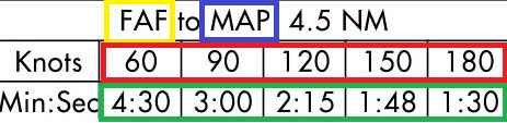
Time and Speed Table and Rate of Climb/Descent Table
- The Time and Speed Table shows the distance from the FAF to the MAP of a non precision approach, and the TIME it takes to reach this point at a specified GROUNDSPEED.
Time and Speed Table
Lighting Box
-
The lighting box depicts the approach light system (ALS) and/or the visual glide slope indicator for straight-in approach runways.
- VASI/PAPI systems are depicted on the approach plates located on the side of the runway.
Lighting Boxes
Missed Approach Icons
- The profile view and missed approach icons indicate the necessary instructions how to perform a missed approach procedure when on an approach and the airport environment is not insight.
Even though there are missed approach icons, the missed approach procedure is also to find in textual.
Landing Minimums
Landing Minimums
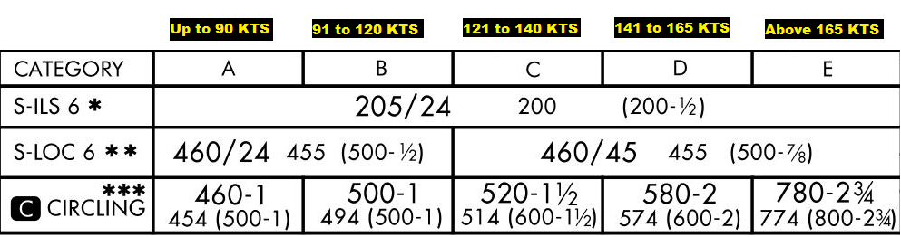
- The landing minimums provide a minimum altitude upon which pilots must establish a certain visibility before a landing can be accomplished. Minimums are affected by aircraft speed, type of approach, obstruction and lighting available.
Landing Minimums
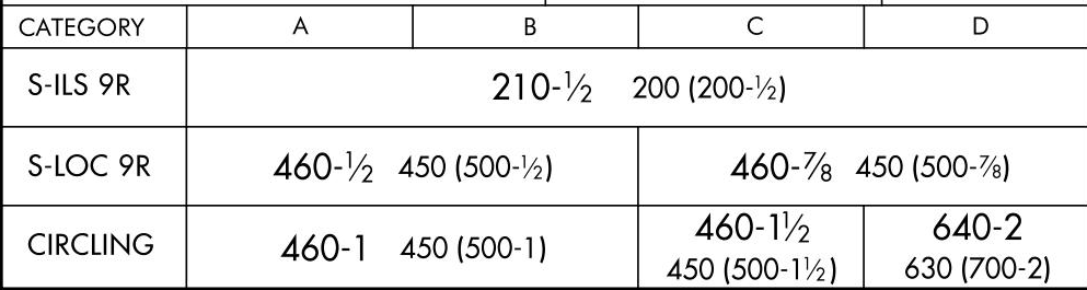
Approach Speed Categories
- The landing minimums categories are based upon on the aircraft approaching at a certain Vref (Reference approach Speed). This speed can be found in most POHs.
- If VRef can not be determined with the POH pilots can figure out this speed by multiplying their Vso times 1.3.
- Ground Speed should be considered when choosing the corresponding landing minimums.
Landing Minimums
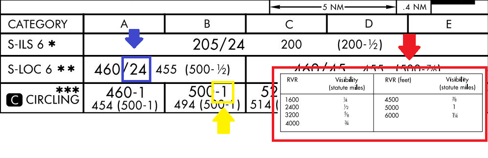
Visibility Requirements
- According to 91.175, pilots may only descend below their approach minimums only if flight visibility is above the one prescribed on the approach
- It is either expressed as prevailing visibility in miles or fraction of miles, or RVR in hundreds of feet.
- If RVR Equipment is inoperative pilots should convert the RVR Value to ground visibility.
Visibility Requirements
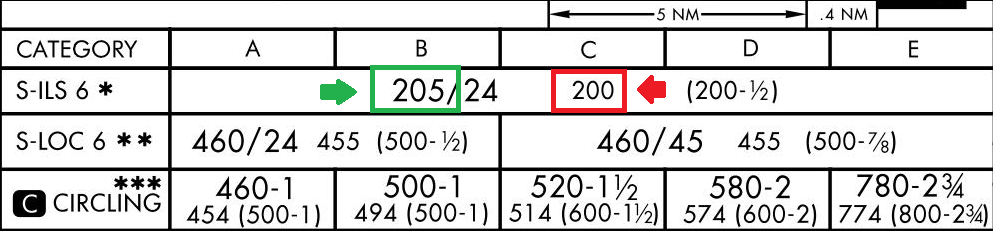
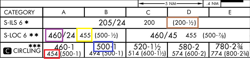
Minimum Descent Requirements
"The minimum altitudes pilots can descend to while performing an approach"
- DA (Decision Altitude) : The altitude on any approach with vertical guidance upon which the pilots must take the decision to continue with the approach and land or perform a missed approach.
- DH (Decision Height): Is DA expressed in terms above the touchdown zone elevation. Can be used to quickly identify if the ceiling will be above DA.
Minimums
- Minimum Descent Altitude (MDA): The minimum altitude (MSL) pilots are authorized to descent to in a straight in non precision approach or a circling approach.
- Height Above Touchdown (HAT) : MDA expressed in terms above the touchdown zone elevation. Can be used to determine if the ceiling will be above approach minimums.
- Height Above Airport (HAA) : It used to determine the Height above the Airport when the Aircraft reached the MDA.
- The minimums in parentheses are used military planning purposes only.
Minimums
Inoperative Components
- When conducting an instrument approach there will always be the chance that some equipment in the airport might be inoperative. If that's the case consult the INOPERATIVE COMPONENTS TABLE found in the front of the TPP, to raise the minimums of the approach accordingly.

Inoperative Components
Airport Sketch
"An airport sketch that increases situational awareness by informing pilot of runway information including lightingn availbe, osbtacles an runway distances"
The symbols include the following:
- Runway Number
- Displaced threshold
- Runway Length and width
- Approach Runway Touchdown zone elevation
- Airport Elevation
- Position and elevation of the control tower
- Declared Runway distances available on the Chart Supplement
Airport Chart and Airport Diagram
Heading and Communications
On both airport charts you will find the following:
-
Airport Identification: airport name, city, state, and IACA identifier.
-
Chart Dates: a revision date and effective date. On TPPs, the volume and chart effective dates are on both sides of the chart.
-
Chart Index Number: helps with filing and recognizing certain features.
-
Elevation: airport elevation.
-
Latitude/Longitude: the exact position of the airport (only on Jeppesen charts)
- Communication: frequencies of the airport. On Jeppesen charts, they are in order, which is normally used when departing the airport. The * indicates part-time operations.
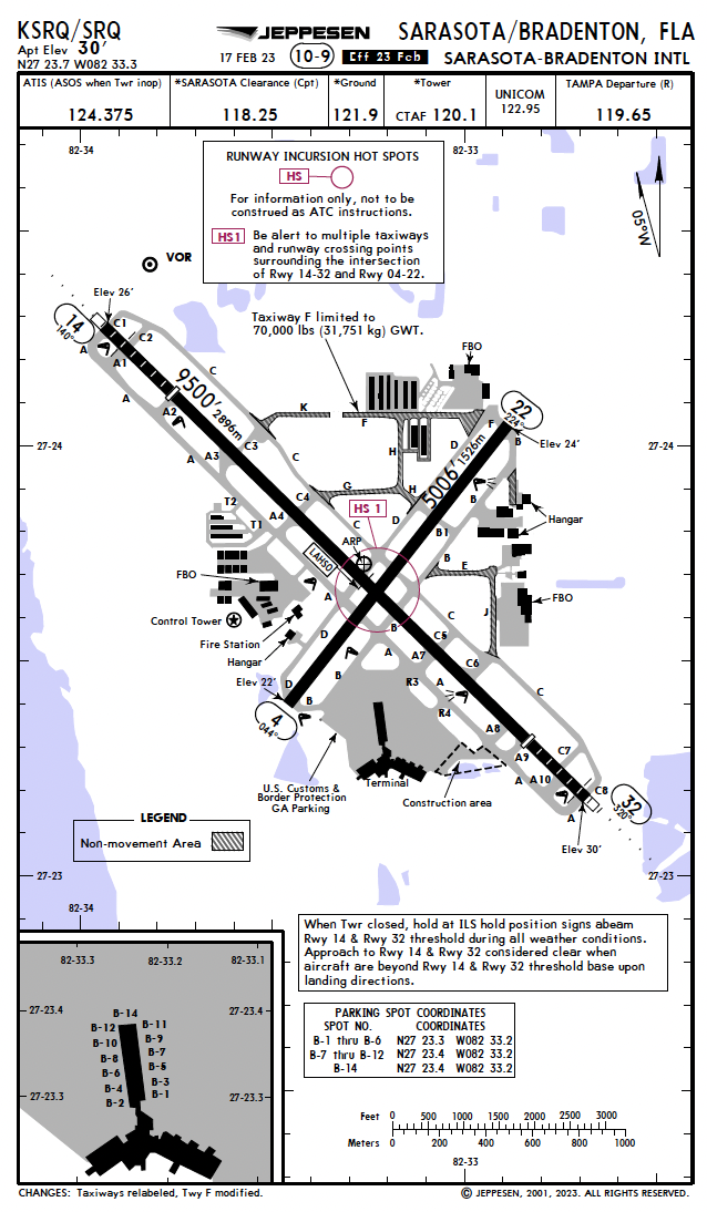
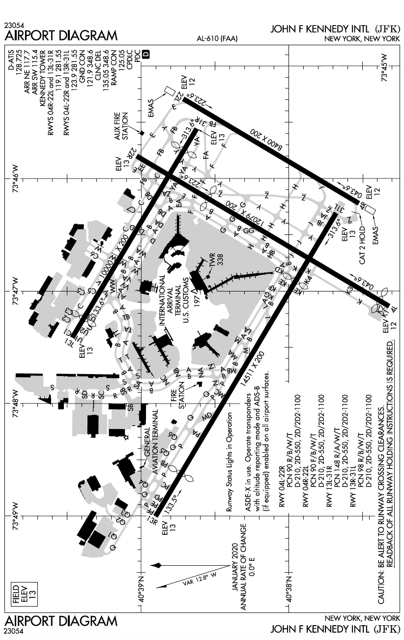
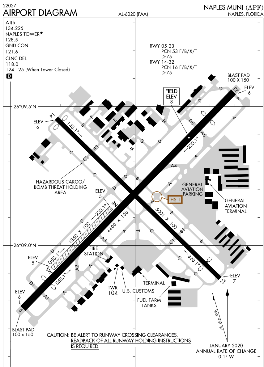
Airport Diagram
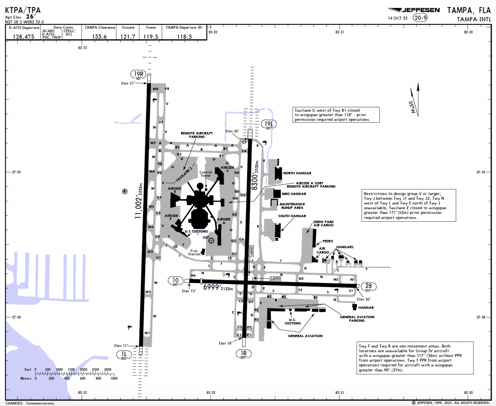
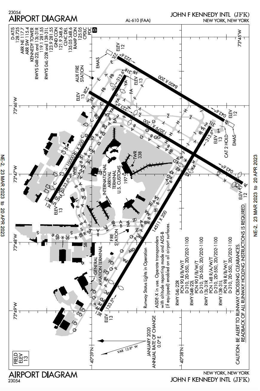
Airport Environment
A plan view of the airport itself with information such as:
Control Tower Location
and Elevation
Airport Beacon
Airport Reference Point
(only on Jeppesen)
Latitude and
Longitude References
Building Reference
Local Magnetic Variation
ARP is the geometric center of all usable runway surfaces
Control Tower Location
and Elevation
Airport Beacon
Airport Field Elevation
Latitude and
Longitude References
Building Reference
Local Magnetic Variation
Runway Information
Runway Numbers and Magnetic Direction
Runway End Elevation
Displaced Treshold
Total Runway Length
Runway Surface
Usuable Runway Lenght
Runway Width
A plan view of the runway itself with information such as:
Hot Spots
Runway and Approach Lighting
Runway Numbers and Magnetic Direction
Runway End Elevation
Displaced Treshold
Runway Length and Width
Hot Spots
Alternate Airports
When do I need an Alternate?
First, let’s start with the basics: § 91.169 – IFR flight plan. I know the FARs use complicated phraseology, and therefore we are looking to simplify and deliver the best approach possible.
§ 91.169 (b) states that you ALWAYS need to file an alternate UNLESS…
1. The airport has an instrument approach procedure AND
2. Appropriate weather reports OR weather forecasts, OR a combination of them, indicate the following:
- 1 hour before to 1 hour after your ETA (at the listed destination), the ceiling will be at least 2,000' AGL, and the visibility will be at least 3 SM. It's called the 1-2-3 rule; this is the easiest way to remember this section.
What is considered an appropriate weather reports or weather forecasts?
Well, METAR is an observation weather report; meanwhile, the TAF is weather forecast observation of the field. For flights less than an hour, a current METAR may be used.
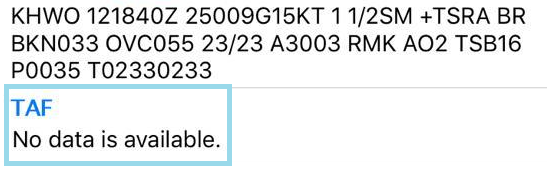
What if the destination has no TAF?
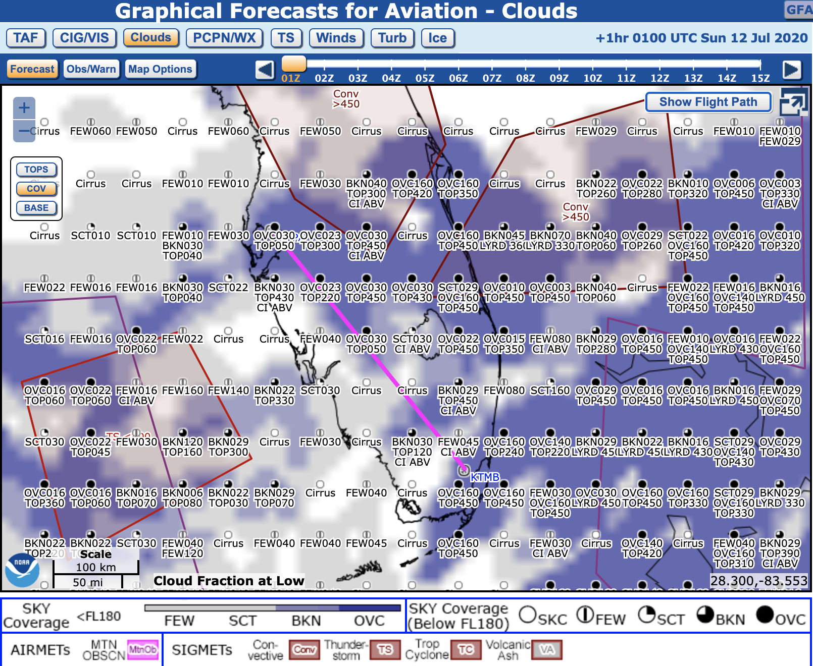
Although the Terminal Aerodrome Forecast (TAF) is preferable, the Graphical Area Forecast (GFA) can be used in its absence. Utilize the "Ceiling/Visibility" tab and the Zulu time sliding bar to determine weather conditions around your arrival.
How to pick an alternate?
§ 91.169 (c)
Great job! Now that you understand when an alternate is needed, let's talk about the conditions an airport must meet to qualify as an alternate.
Remember, an alternate is a plan B; a professional pilot always has a plan B. As a result, you must verify different factors before even attempting to choose an airport as an alternate.
1. You have to assess the field. Use risk management, and determine the best area to pick an alternate airport.
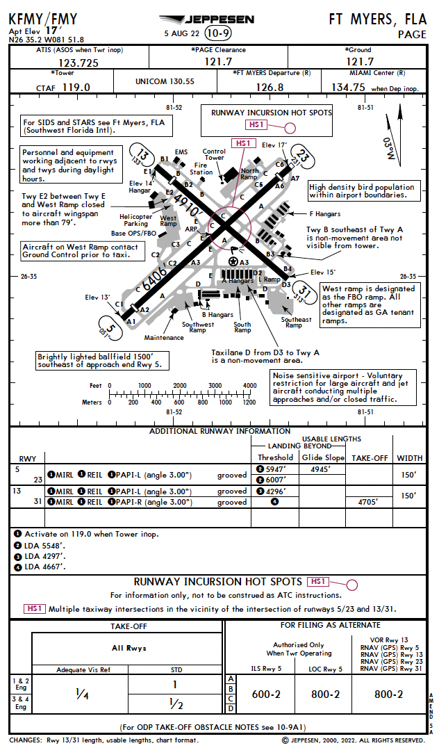
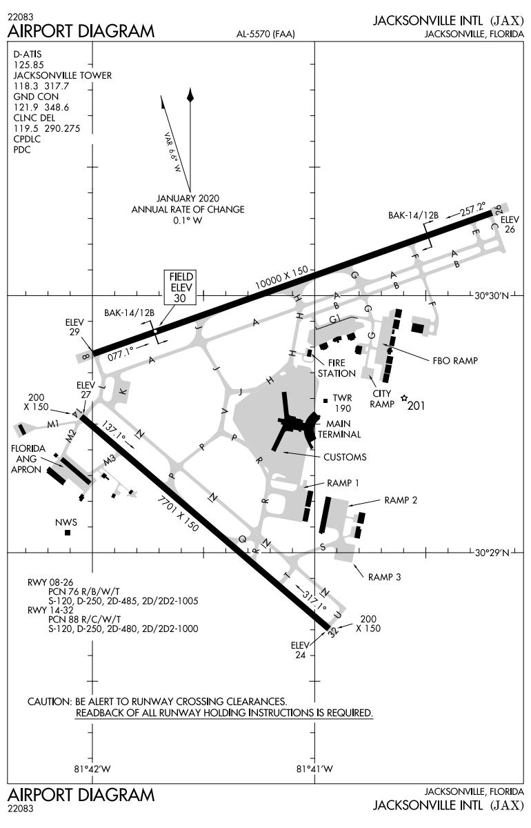
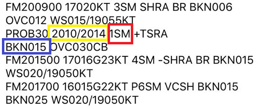
For example, let us imagine you are planning a cross-country flight from KOPF to KJAX. There are significant areas of thunderstorms north of KJAX moving southeast. Your expected time of arrival is 23:00 Zulu. Following the regulation § 91.169 (c), you will need an alternate because a probability of low visibility is depicted on the TAF. After reviewing the forecast and current weather, you determine the best possible option will be southwest of the field due to the potentially hazardous weather that exists north of KJAX moving southeast.
2. Once you identify the possible alternates, now it's time to determine if they comply with the requirements specified in § 91.169 (c).
2. Once you identify the possible alternates, now it's time to determine if they comply with the requirements specified in § 91.169 (c).
- No person may include an alternate airport in an IFR flight plan unless appropriate weather reports or weather forecasts, or a combination of them, indicate that, at the estimated time of arrival (ETA) at the alternate airport, the ceiling and visibility at that airport will be at or above the following weather minima:
- No person may include an alternate airport in an IFR flight plan unless appropriate weather reports or weather forecasts, or a combination of them, indicate that, at the estimated time of arrival (ETA) at the alternate airport, the ceiling and visibility at that airport will be at or above the following weather minima:
- If a usable precision approach is available: 600 ft ceilings AND 2 SM of visibility.
- If only a non-precision approach is useable: 800 ft AND 2 SM of visibility.
- If no instrument approaches are available: Descent from the MEA and landing must be conducted under basic VFR.
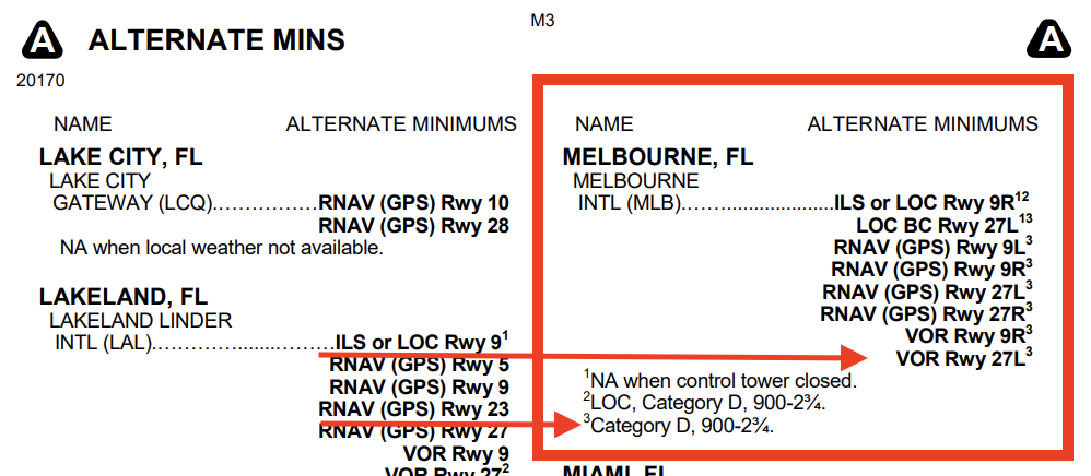
3. In the real world, not all airports follow the standard minimums we just listed above here. If that's the case, the airport has nonstandard alternate minimums. So how do you find those alternate minimums?
3. In the real world, not all airports follow the standard minimums we just listed above here. If that's the case, the airport has nonstandard alternate minimums. So how do you find those alternate minimums?
a) If an airport has nonstandard IFR alternate minimums information published, you will know by seeing a symbol that looks like a triangle with an 'A' in it on the Notes section's approach plate.
b) To view the non-standard IFR alternate minimums information, you will need to go to the front of the TPP to the Alternate Mins Section (M1), then search for the airport, and use the notes for the desired approach.
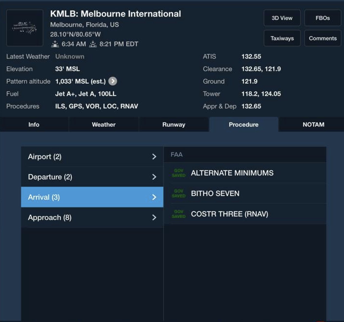
c) If you're using ForeFlight, you can click on the "alternate minimums" tab under "arrival procedures." Sorted by city name, you'll find the new weather minimums you must use to determine if an airport is eligible to file as an alternate.
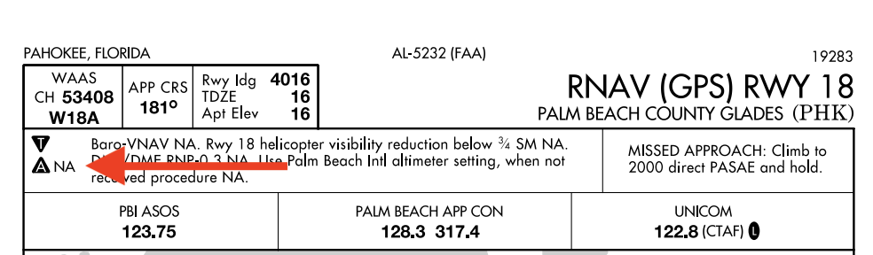
d) Not all the airport are quality as an alternate, you will know by seeing an NA before the triangle with an 'A' in it on the Notes section's approach plate.
Alternate Airport Considerations
- GPS users (without WAAS) on an IFR flight plan can use GPS-based approaches at either their destination or alternate, but not at both locations.
- WAAS users without BARO-VNAV may plan to use LNAV approaches at any airport (destination, alternate, or both).
- WAAS equipped with BARO-VNAV may plan for LPV or LNAV/VNAV at both the destination and alternate.
For more info about LPV and LNAV approaches, refer to GL 18