GL 13 Approach Procedures

Rev 02/2025
Disclaimer
Students should use their textbooks, syllabus, and Airman Certification Standards (ACS) as their primary sources of information. EcFlight is an online training tool designed to simplify and enhance your ground school learning experience. However, it is not a substitute for FAA- or school-approved study materials. Before using these slides for study, always refer to your officially approved resources, such as the Jeppesen physical or electronic book and other FAA-approved materials.
Reference Books
- Pilot's Handbook of Aeronautical Knowledge(FAA-H-8083-25B). (2016). Oklahoma City, OK: United States Department of Transportation, Federal Aviation Administration, Airman Testing Standards Branch.
- Instrument Flying Handbook faa-h-8083-15B. (2012). Oklahoma City, OK: United States Department of Transportation, Federal Aviation Administration, Airman Testing Standards Branch.
- Instrument Pilot Syllabus (10001785-003). (2015). Englewood, CO: Jeppesen.
Reference Multimedia
- IFR Enroute Aeronautical Charts and Planning. (2019, March 08). Retrieved from https://www.faa.gov/air_traffic/flight_info/aeronav/digital_products/ifr/
- IFR Enroute Aeronautical Charts and Planning. (2019, March 08). Retrieved from https://www.faa.gov/air_traffic/flight_info/aeronav/digital_products/ifr/
Index

Preparing for the Approach
- During Preflight planning, you should review the approach charts for your destination.
- ATC or ATIS will advise you of the type of approach to expect to help you plan your arrival actions. Remember this is not clearance and conditions might change the kind of approach.
Approach Overview
- The Approach Overview is the initial review of the expected approach procedure.
- Determine the factors that will affect the ability to perform the approach ahead of time.
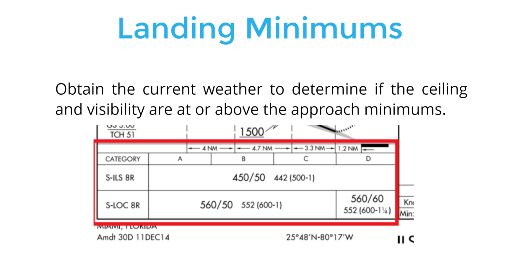
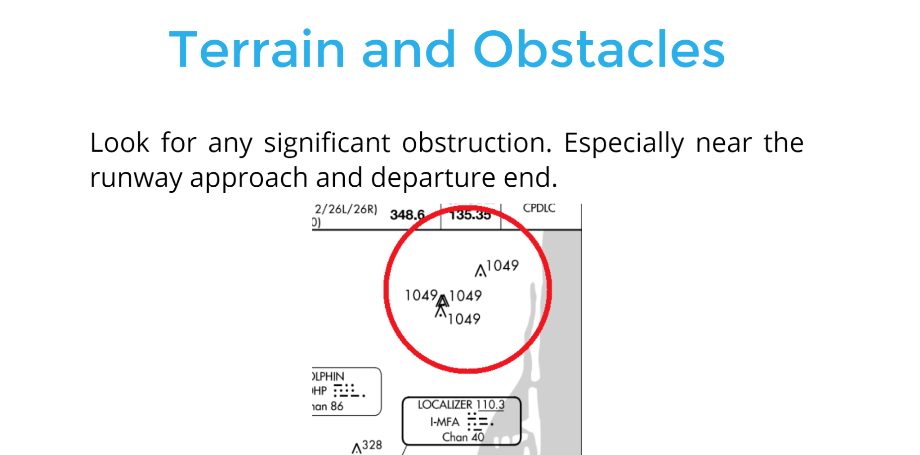
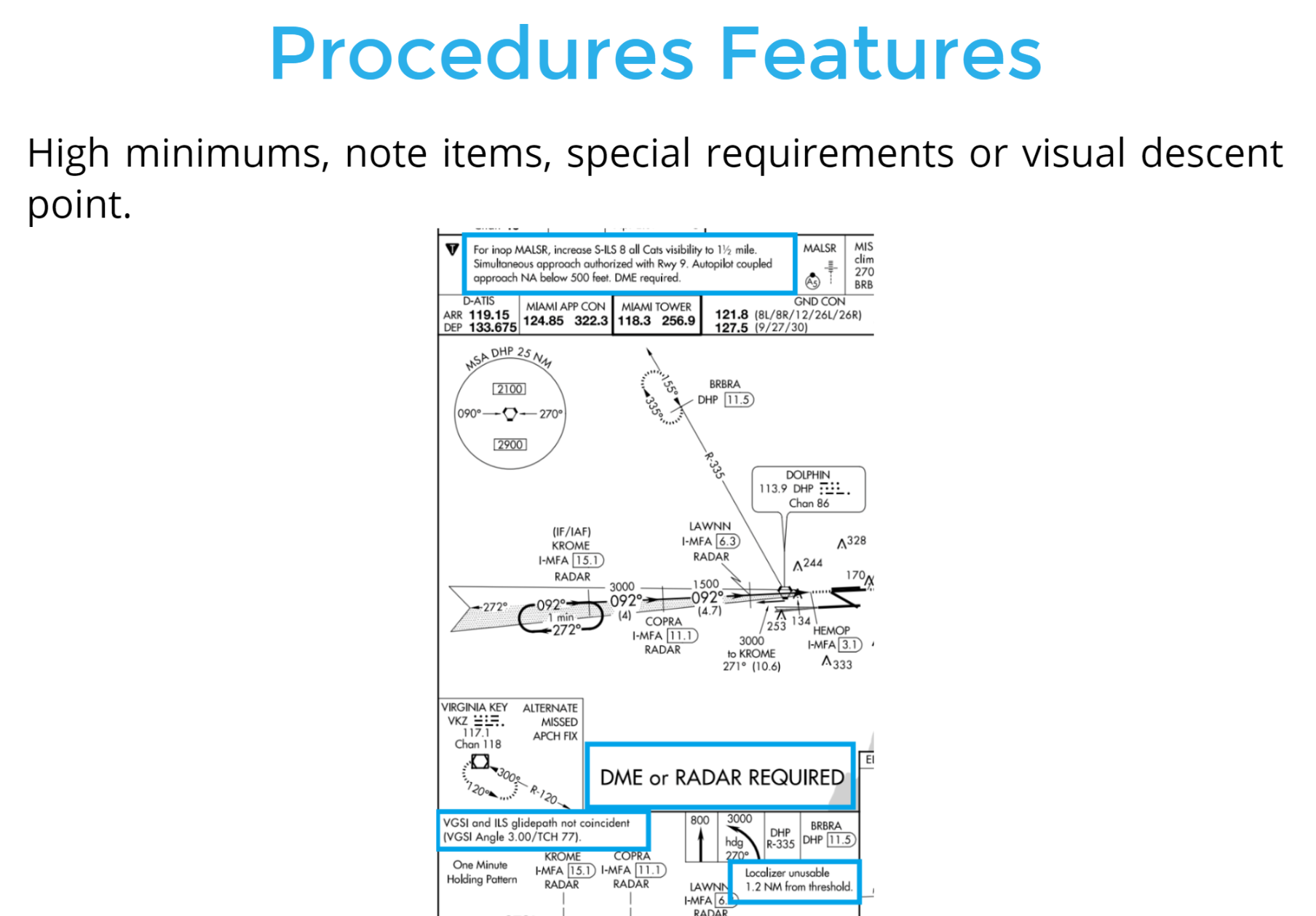
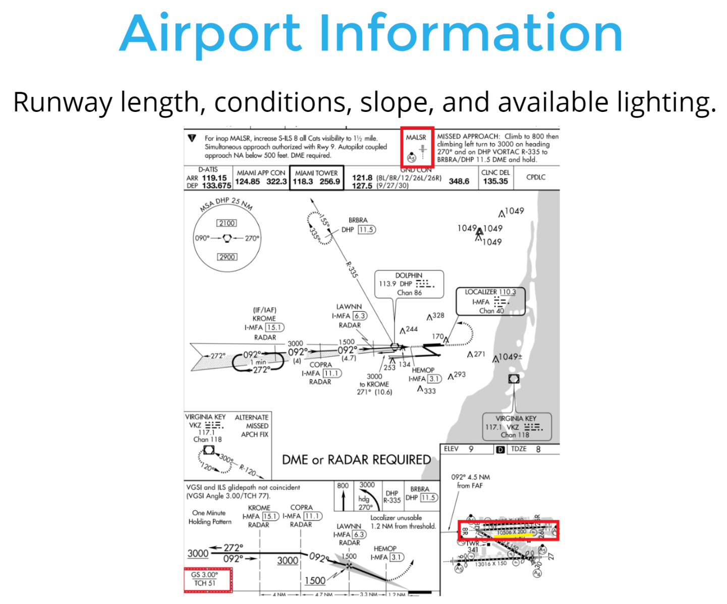
- Landing minimums, terrain, obstacles, and specific equipment are elements you should include.
2) Landing Minimums
1) Terrain and Obstacles
3) Procedures Features
4) Airport Information
Approach Briefing
- Familiarize yourself with the approach after ATC has advised you the approach to expect.
- Check for specific approach procedure. Verbalize the primary elements of the approach.
Voice By: John Duque
Approach Clearance
The pilot must execute the entire procedure starting at an IAP or an associated feeder route unless you are radar vectored to the final approach course.
Text
Lets Review...
Performing the Approach
-
Performing the approach to the transition from the enroute to the terminal environment.
- Complying with the limitations during the instrument approach.
Straight-In Landing vs. Circling Approach
- When the final approach course alignment is within 30° of the runway centerline.
- Minimum maneuvering is required to align the airplane with the runway.
Straight-In Landing
- The final approach course is more than 30° of the runway centerline.
- Unfavorable winds or runways are not clearly defined on the airfield.
- The descent angle is greater than 400 ft/nm.
Circling Approach
Straight-In Minimums:
The localizer course of 044° is aligned with runway 04 of KJFK.
The straight landing minimums for the ILS approach for all aircraft categories is a DA of 212 feet MSL and visibility RVR 1.800 feet.
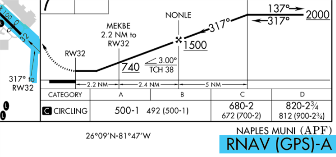
Circling Minimums:
Wind 130° at 30Kts. Runway favorable is 13. N123EC clear ILS RWY 4R circle to RWY 13.
The MDA is 640 feet MSL and visibility of 1 statute mile, 13/4 or 2 miles applies depending on aircraft category.
For example
Procedures that ONLY provide circling minimums are identified by a letter following the primary approach NAVAID.
Circling Only
Straight-In Approach
ATC may specify in the approach clearance “CLEARED STRAIGHT-IN (type) APPROACH” to ensure that the pilot understands that the procedure turn or hold-in-lieu-of PT (Procedure Turn) is not required to be flown.
Can be initiated with:
1) Completion of a DME arc.
2) Vector to final approach course.
3) A fix that is almost aligned with the final approach course.
4) NoPT is described on the approach.
Example
DME Arc: "N123EC, join the arc at JOMIN, maintain 3.000 to intercept the final approach course of 055.
Fix: "N123EC Cross Gulpe at 2.000ft, clear straight-In ILS Z RWY 6 approach".
Vectors: "N123EC, 4 miles northwest of FLATE, turn right heading 090 maintain 2.000 until established on the localizer. Clear ILS Z RWY 6 approach.
Use of ATC Radar for Approaches
- There are two types: Precision Approach Radar (PAR) and Airport Surveillance Radar (ASR).
- ATC can indicate when to begin and end turns. as well as vertical guidance depending on the type or approach.
- Information is published in tabular form in the front of the TPP booklet.

- Remember is the pilot’s responsibility to ensure the approach and landing minimums listed for the approach are appropriate
- The pilot has the ability to use radar to execute a no-gyro approach. Assuming standard rate turns.
Course Reversals
- Depicted on the chart as procedure turns, holding pattern or a teardrop procedure.
- They are generally within 10NM of the primary NAVAID.
- The maximum speed is 200KTS inside the course reversal.
Course Reversal
- Execute the turns on the same side of the approach course. Example: The arrow is to the right, Right turns will be performed.
- Remain within the specified distance from the primary NAVAID.
- The pilot must comply with the crossing restrictions.
Holding Pattern
or
Teardrop
ATC: "N123EC, Fly direct to JULED, hold as published and advise when established inbound".
Procedure turn Obstacle Clearance
- Conducted when many aircraft are waiting for approach clearance.
- The controller will not specifically state, “Timed approaches are in progress.”
- Each pilot in the approach sequence is given advance notice of the time they should leave the holding point on approach to the airport.
the pilot should adjust the flightpath or holding in order
to leave the fix as closely as possible to the designated time."
Timed Approaches From a Holding Fix
Understanding how procedures change based on the use of DA or MDA and when you can descend below these minimums is critical for safe operation during instrument meteorological conditions (IMC).
Final Approach
Operating Below the DA or MDA §91.175
Pilots may not operate an aircraft at any airport below the authorized MDA or continue an approach below the authorized DA/DH unless:
1. The aircraft is continuously in a position from which a descent to a landing on the intended runway can be made at a normal descent rate using normal maneuvers;
2. The flight visibility is not less than that prescribed for the approach procedure being used; and
3. At least one of the following visual references for the intended runway is visible and identifiable to the pilot:
a) Approach light system (See exception)
b) Threshold
c) Threshold markings
d) Threshold lights
e) Runway end identifier lights (REIL)
f) Visual approach slope indicator (VASI)
g) Touchdown zone or touchdown zone markings
h) Touchdown zone lights
i) Runway or runway markings
j) Runway lights
§91.175
If using only the Approach light system
the pilot may not descend below 100 feet above the touchdown zone elevation using the approach lights as a reference unless the red terminating bars or the red side row bars are also distinctly visible and identifiable."
§91.175

Descending to the DA or MDA
Precision approach, descending to the Decision altitude (DA).
Non-precision approach, descending to the Minimum Decision altitude (MDA).
Execute the missed approach when reaching the DA.
Remain At or above the MDA until reaching the Missed approach point (MAP). Then, execute the missed approach.
Example of Precision approach DA minimums
If descending to the 305 ft (DA) on the ILS 4 at La Guardia Airport.
Execute the missed approach upon arrival to 305 ft and no runway environment insight.
Demostration
Example of Non-Precision approach MDA minimums
-
If descending to the 640 ft (MDA) on the LOC RWY 4 at La Guardia Airpot.
- Maintain 640 ft upon arrival to the MAP (1.1 NM from LGA VOR/DME) and no runway environment insight.
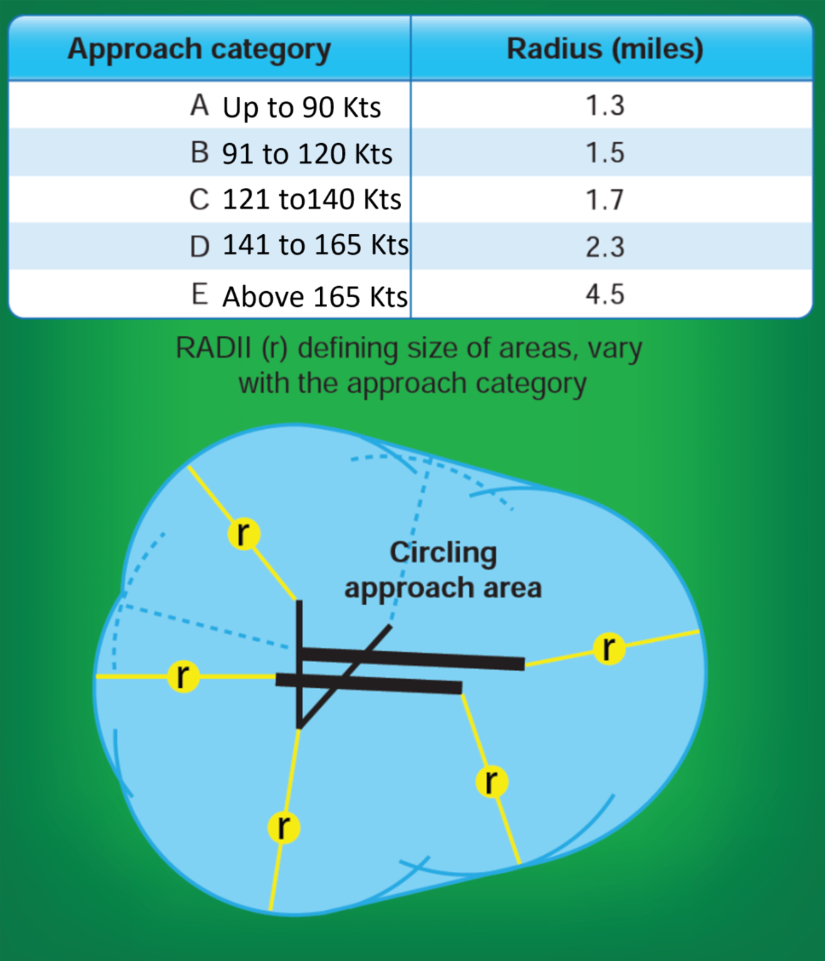
Circling Approaches
- Provide a minimum of 300 feet of obstacle clearance in the circling area.
- Fly no lower than the circling minimums until positioned to make a final descent for a landing.
The circling maneuver
Sidestep Maneuver
- ATC may authorize a side-step maneuver to either one of two parallel runways that are separated by 1,200 feet or less, followed by a straight-in landing on the adjacent runway.
- The pilot is expected to commence the side-step maneuver as soon as possible after the runway or runway environment is in sight.
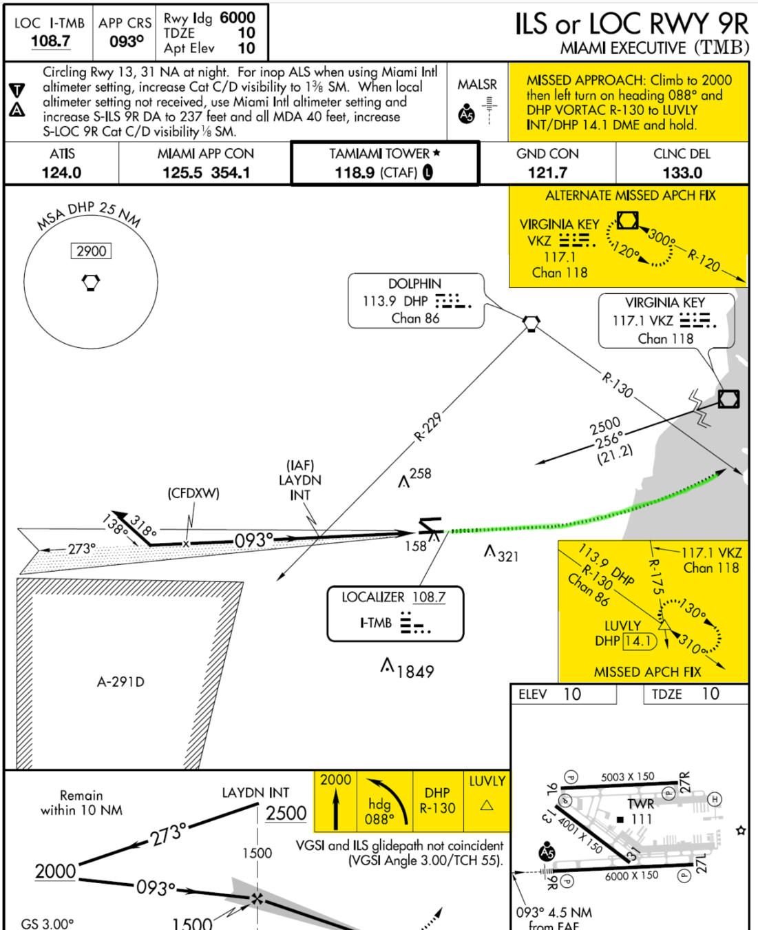
Missed Approach Procedures
A MAP is formulated for each published instrument approach and allows the pilot to return to the airway structure while remaining clear of obstacles.
When a MAP is initiated:
- A climb pitch attitude should be established while setting climb power.
- Configure the aircraft for a climb and turn to the appropriate heading.
- Advise ATC that a missed approach is being executed and request further clearances.
Graphical Missed Approach Procedure
Textual Missed Approach Procedure
Pilots should immediately execute the MAP If:
- Whenever the requirements for operating below DA/
DH or MDA are not met §91.175
- When the aircraft is below MDA, or upon arrival at the MAP and runway environment is not sight.
- Whenever an identifiable part of the airport is not
visible to the pilot during a circling maneuver at or
above MDA; or
- When so directed by ATC.
Missed Approach during Circling to land
- If visual reference is lost while circling to land from an
instrument approach, execute the appropriate missed approach procedure. Make the initial climbing turn toward the landing runway and then maneuver to intercept and fly the missed approach course.
Visual and Contact Approach
Visual Approach
- When weather conditions permit, ATC can authorize the pilot to conduct a Visual Approach in lieu of the published approach procedure.
- Either the pilot or ATC can initiate a visual approach.
- The airport or aircraft to follow must be in sight.
- The ceiling must be at least 1,000 ft AGL, and visibility must be 3 statute miles. The pilot must remain clear of clouds.
Contact Approach
- Reported ground visibility must be at least 1 statute mile and remain clear of clouds.
- Must be requested by the pilot.
- The airport must have a published instrument approach, and you must remain clear of clouds.
Charted Visual Flight Procedures (CVFPs)
- Airports with control towers for environmental or noise considerations, as well as when necessary for the safety and efficiency of air traffic operations.
- Designed primarily for turbojet aircraft, CVFPs depict prominent landmarks, courses, and recommended altitudes to specific runways.