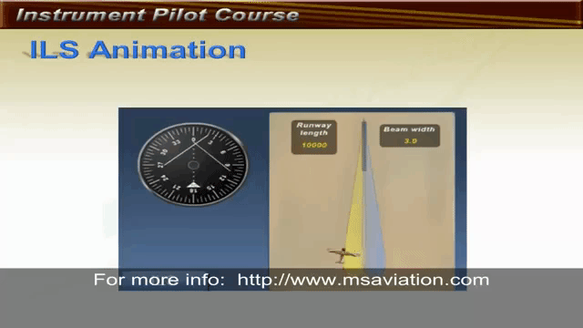
GL 13.2 ILS Approach

Rev 02/2025
Disclaimer
Students should use their textbooks, syllabus, and Airman Certification Standards (ACS) as their primary sources of information. EcFlight is an online training tool designed to simplify and enhance your ground school learning experience. However, it is not a substitute for FAA- or school-approved study materials. Before using these slides for study, always refer to your officially approved resources, such as the Jeppesen physical or electronic book and other FAA-approved materials.
Reference Books
- Pilot's Handbook of Aeronautical Knowledge(FAA-H-8083-25B). (2016). Oklahoma City, OK: United States Department of Transportation, Federal Aviation Administration, Airman Testing Standards Branch.
- Instrument Flying Handbook faa-h-8083-15B. (2012). Oklahoma City, OK: United States Department of Transportation, Federal Aviation Administration, Airman Testing Standards Branch.
- Instrument Pilot Syllabus (10001785-003). (2015). Englewood, CO: Jeppesen.
- Air Traffic Plans and Publications. (n.d.). Retrieved from https://www.faa.gov/air_traffic/publications/
Reference Multimedia
- IFR Enroute Aeronautical Charts and Planning. (2019, March 08). Retrieved from https://www.faa.gov/air_traffic/flight_info/aeronav/digital_products/ifr/
- IFR Enroute Aeronautical Charts and Planning. (2019, March 08). Retrieved from https://www.faa.gov/air_traffic/flight_info/aeronav/digital_products/ifr/
- Antena-Localizer-Aeroparque-2. (n.d.). Retrieved from http://aeromarket.com.ar/noticias/3-aeropuertos-con-nuevas-cartas-de-aproximacion-pbn/attachment/antena-localizer-aeroparque-2/
- Msaviation. (2011, April 12). Retrieved June 10, 2019, from https://www.youtube.com/watch?v=v8OyEWsTi1g
- ILS antenna. (n.d.). Retrieved from http://avineering.com/gp.html
- S. (2018, November 01). Proficiency: Needle work. Retrieved from https://www.aopa.org/news-and-media/all-news/2018/november/pilot/proficiency-needle-work
- Marker beacon system. (n.d.). Retrieved from https://en.ppt-online.org/471683
Index

ILS Categories and Components
- The ILS system provides both lateral and Vertical guidance to a specific runway.
- Use Ground-based stations to receive Guidance, range or visual information.
- It is considered a precision approach (PA).
ILS Categories
- Category I: DH 200 feet and RVR 2400 feet (with TZ and CL lighting, RVR 1800 feet).
- Category II: DH 100 feet and RVR 1200 feet.
-
Category III:
- A: No DH or DH below 100 feet and RVR not less than 700 feet.
- B: No DH or DH below 50 feet and RVR less than 700 but not less than 150 feet.
- C: No DH and no RVR (Requires Autoland Systems).
Categorized into three different types:
ILS Components
- Guidance: Localizer\Glide Slope
- Range Component
- Visual Component
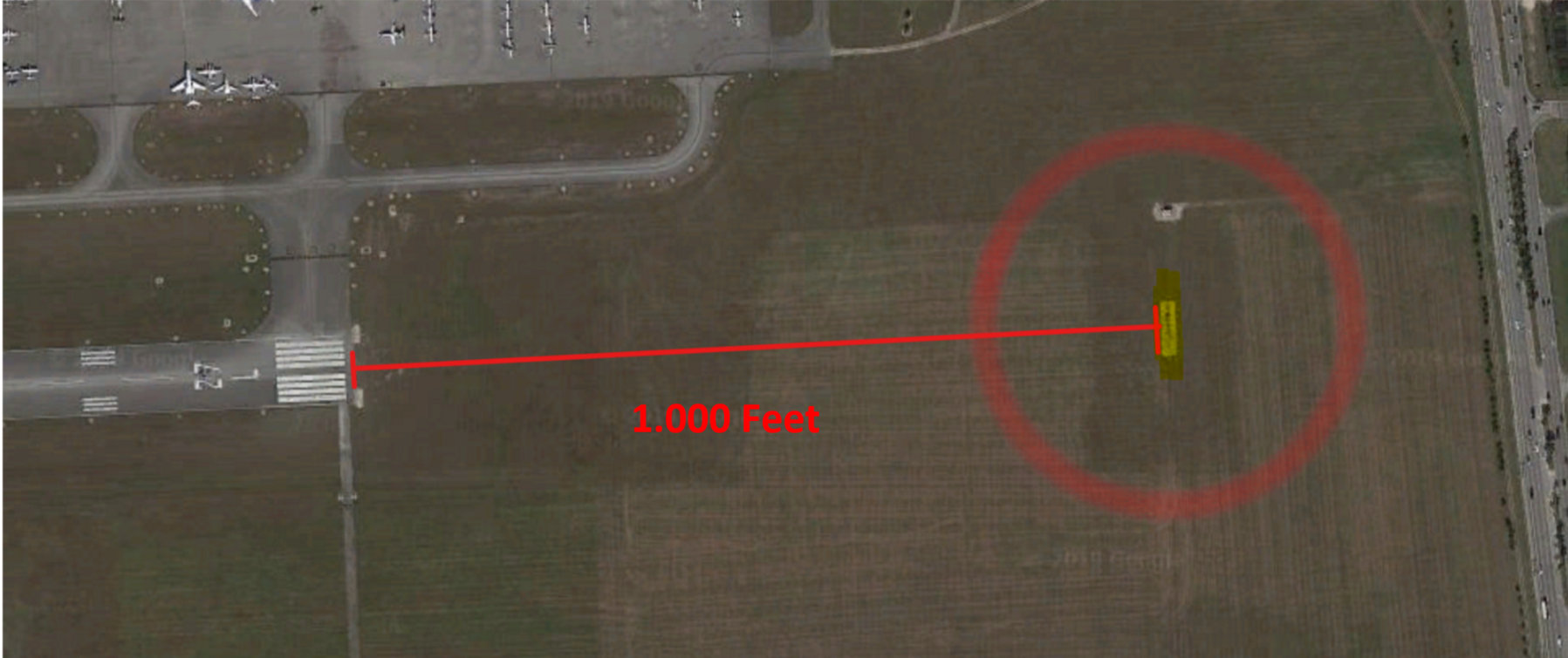
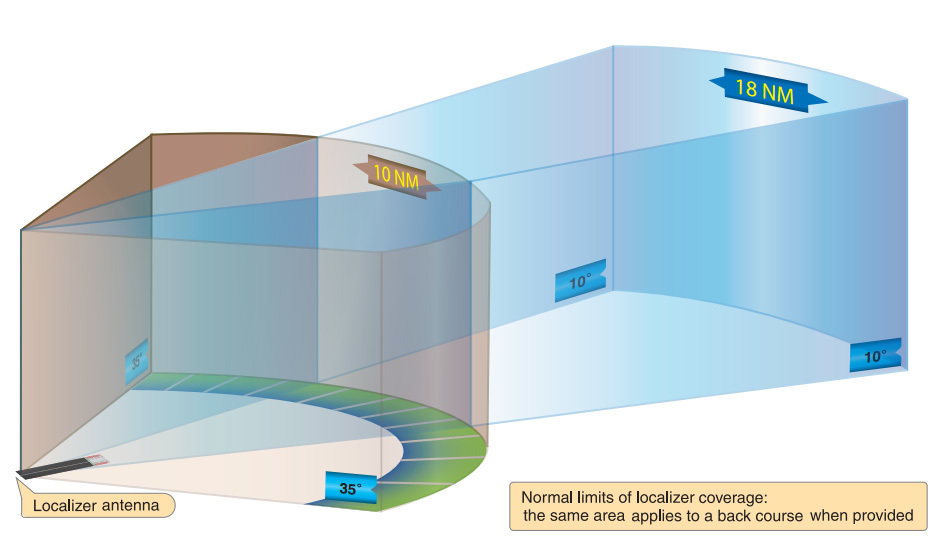
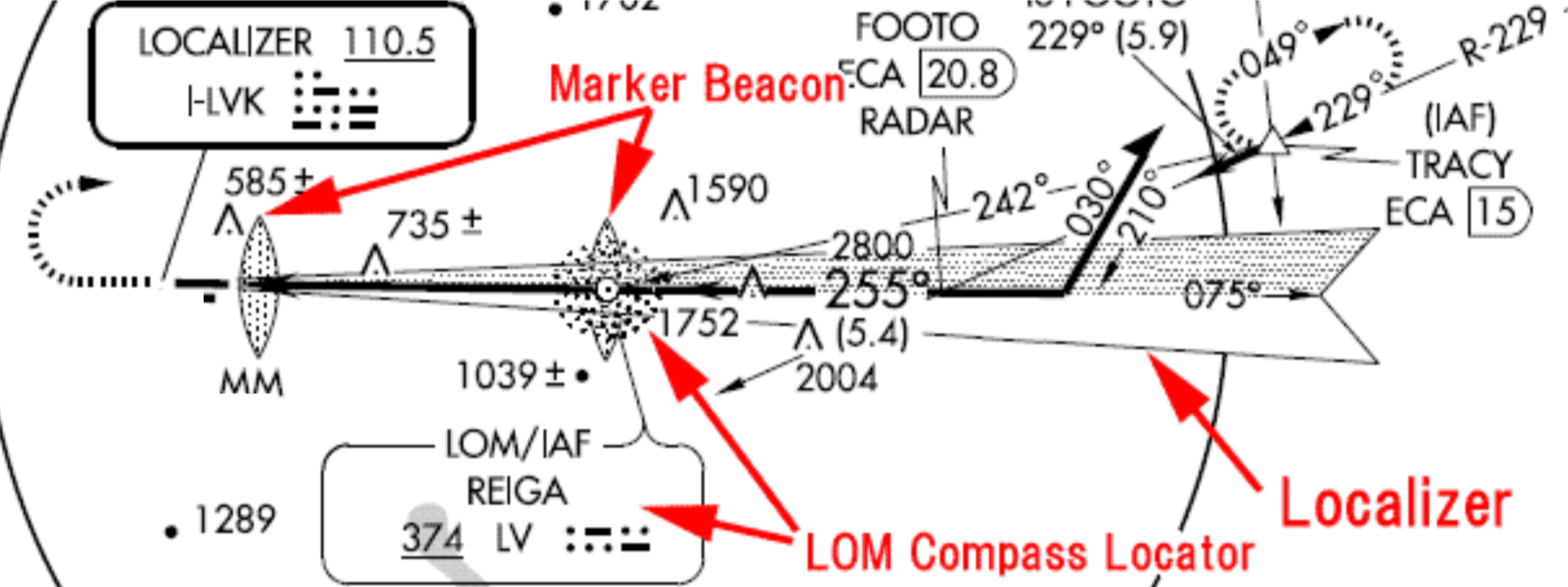
Localizer
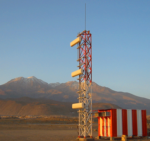
- The localizer provides Horizontal guidance. It aligns the aircraft with the center of the runway.
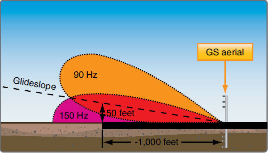
- The localizer (LOC) ground antenna is located 1,000 ft from the end of the runway.
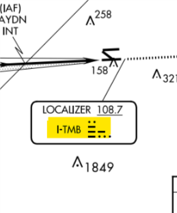
- Frequencies vary from 108.1 - 111.95 VHF.
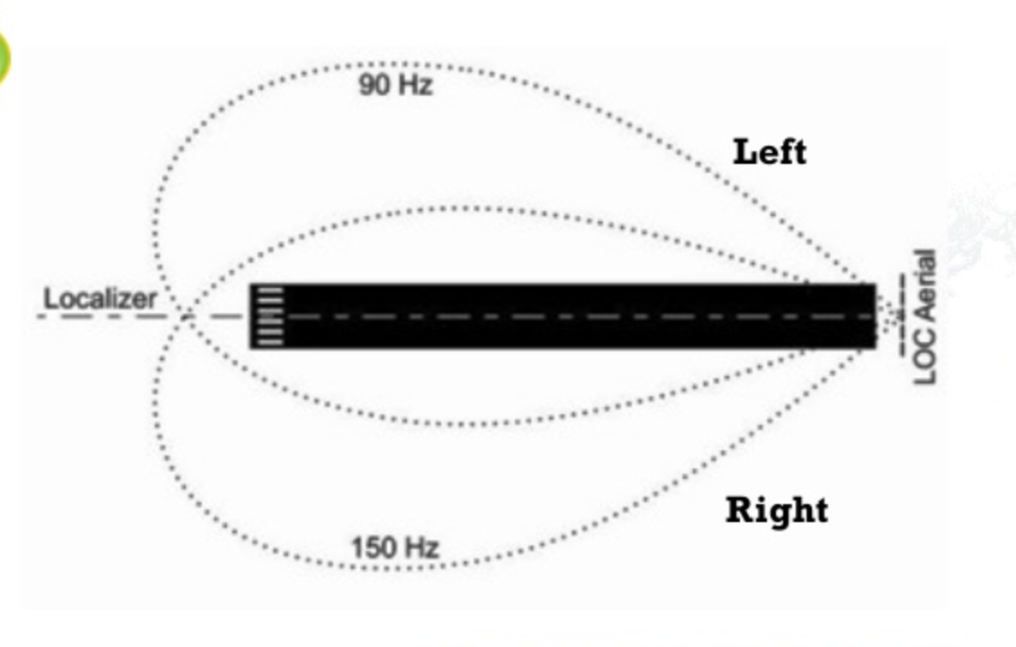
- The localizer transmits two signals which overlap at the center. the left side has a 90Hz and right has 150 Hz modulation.
- It includes a front course and a back course.
- The signal is oriented to one single magnetic direction. Therefore, the course selected on the OBS will not affect the deviation indications.
Indication
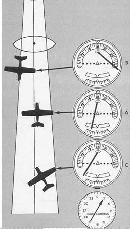
- When tracking the front course localizer towards the runway using a basic VOR indicator, the CDI sensing is normal. Needle deflects to the right, the aircraft must turn right to intercept.
- When outbound or on the back course of the localizer, expect reverse sensing. Avoid confusion by twisting the OBS selector to the outbound course.
- Each localizer facility is audibly identified by a three-letter designator transmitted at frequent regular intervals. The ILS identification is preceded by the letter “I” (two dots).
- As you approach the runway you will notice the CDI is more sensitive than VOR navigation.
- Make small corrections to help prevent overshooting the desire course.
Glide Slope
- The glide slope provides Vertical guidance to the runway of approximately 3°.
- It transmits a glide path beam 1.4° wide.
- Frequency is paired with the localizer. As a result, glides slope channel is automatically select when localizer frequency is set.
Indication
- Deflection of the GS needle indicates the position of the aircraft with respect to the glide path.
- When the aircraft is above the glide path, the needle is deflected downward. When the aircraft is below the glide path, the needle is deflected upward.
- Each dot displacement on your glide slope is equal to a specific distance from the glide path.

Range Information
- Provide position of the aircraft in relationship with the runway.
- The antenna is designed to produce an elliptical pattern.
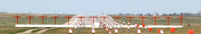
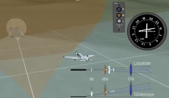
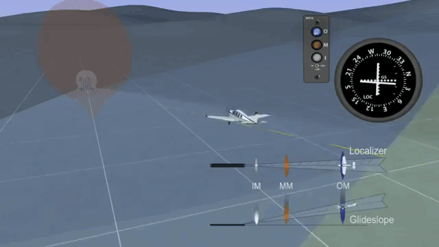
Marker Beacons
Composed of:
- Outer Marker (OM)
- Middle Marker (MM)
- Inner Marker (IM)
- Back Course Marker
Marker Beacons can be replaced with:
(1) VOR Radial.
(2) DME distance.
(3) Low power NDB.
(4) Radar Fix.
Overview
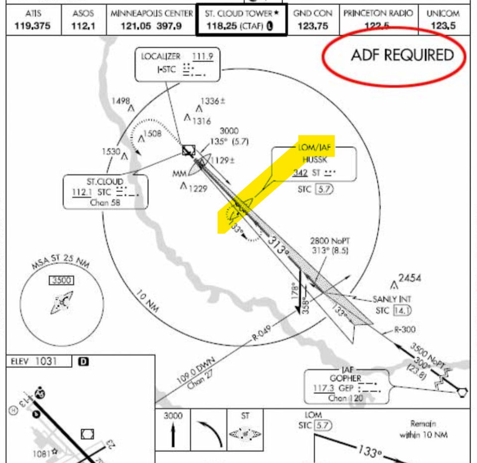
Compass Locator
- Some ILS approaches use low power or medium frequency (L/MF) radio beacon.
- It is also referred to as a Locator Outer Marker (LOM).
- Some locations use a high power NDB that is in combination with the outer marker.
Visual Component
- Visual identification of the ALS by the pilot must be
instantaneous, so it is important to know the type of ALS before the approach is started.
Flying An ILS Approach
- Before intercepting the ILS glide slope. Aircraft must be stabilized to keep the aircraft on the localizer centerline.
- Fly a constant speed for smooth descend.
- 0.5 NM before the glide slope interception extend the flaps and landing gear. Start a descend upon intercepting the glide slope.
- Use small pitch and power adjustments to keep the glideslope center.
- Rate of descending depends primarily on the aircraft's ground speed. The lowers the ground speed, the lower the rate of descent and vice versa.
Use this Methods to calculate the rate of descent
- Ground speed X 5
Or
- Ground speed / 2 *10
For example:
1) 100 Gs * 5 = 500 fpm
2) 100 Gs / 2 = 50
50x10 = 500 fpm
For a 3° Glideslope
Chart Method
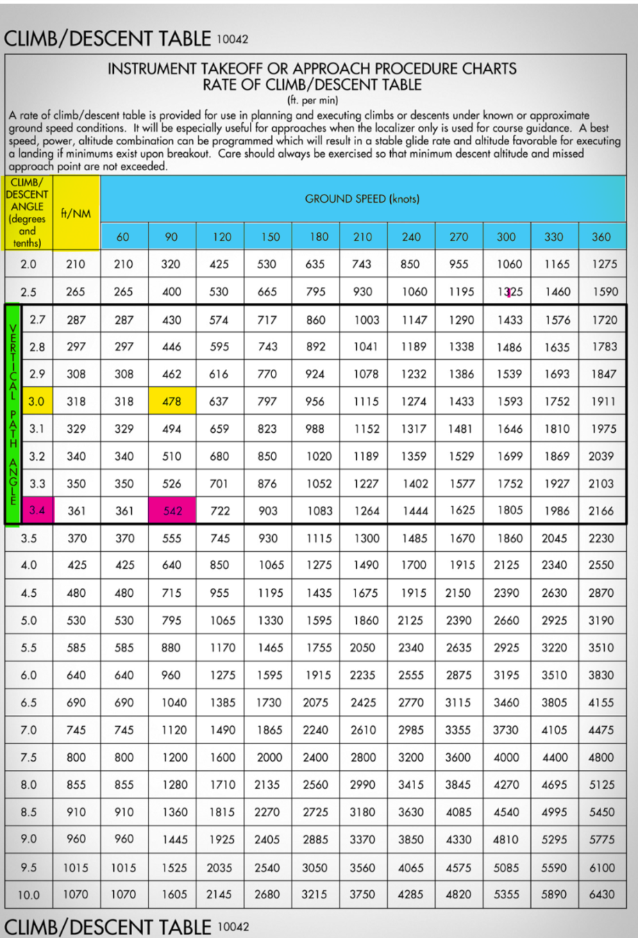
Located at the (back of the TPPs publication).
- If the pilot reaches Decision Altitude (DA) and no visual contact with the runway environment has been established.
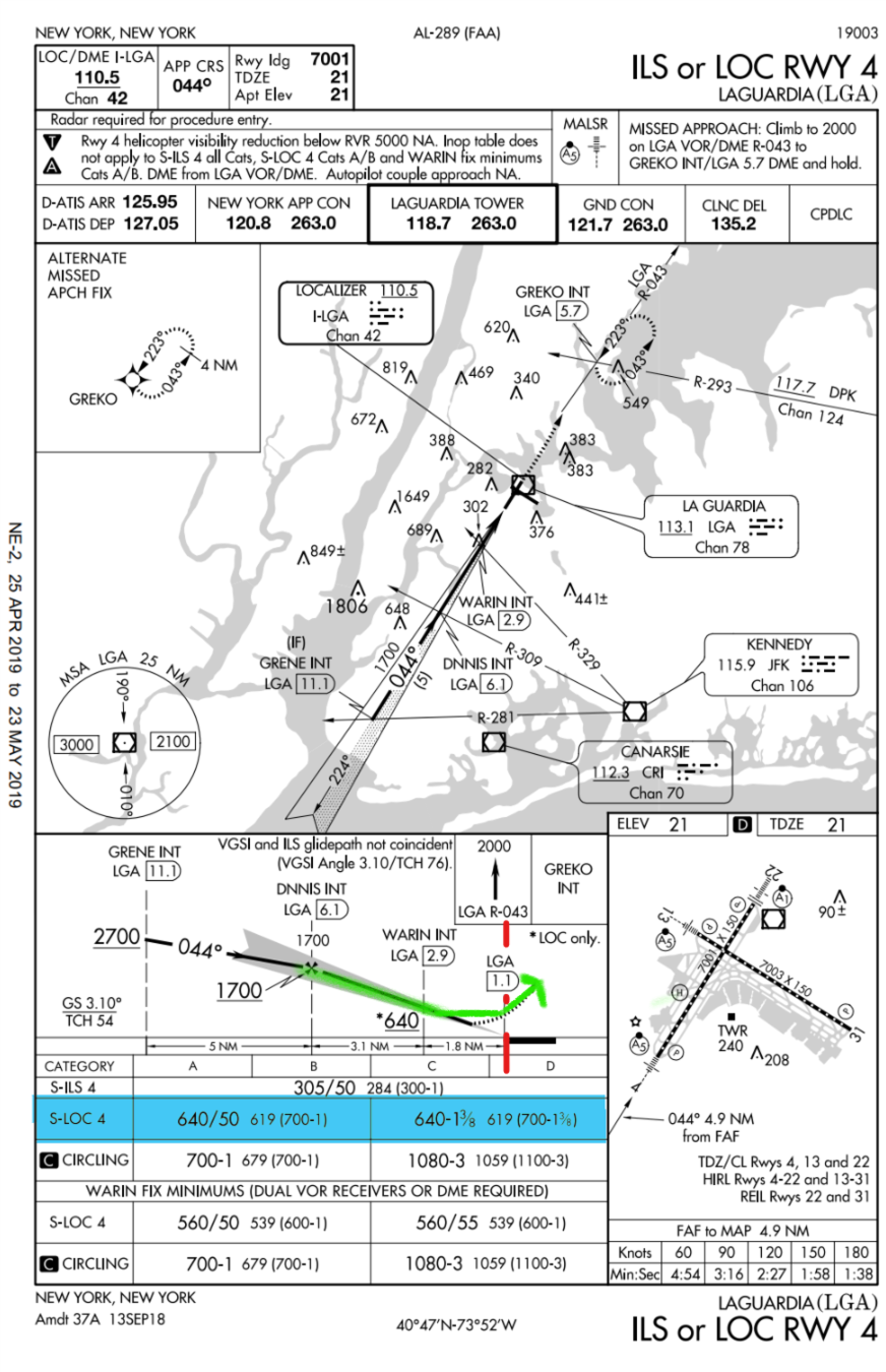
When to Perform a Missed Approach on an ILS?
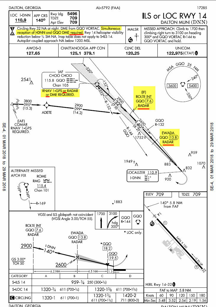
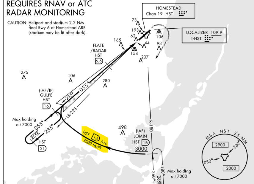
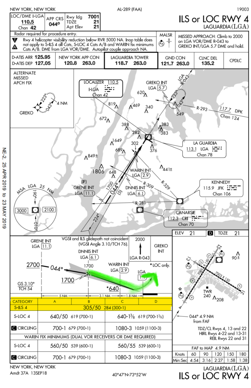
Flying a Straight-In ILS Approach
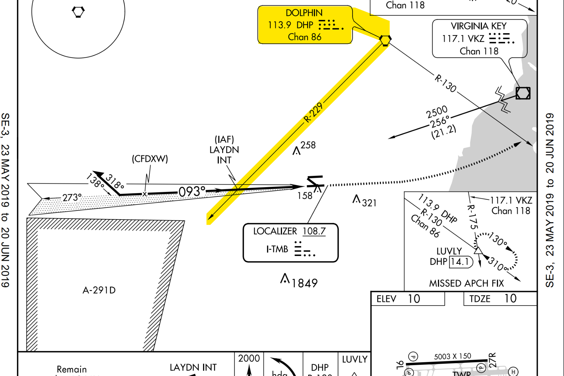
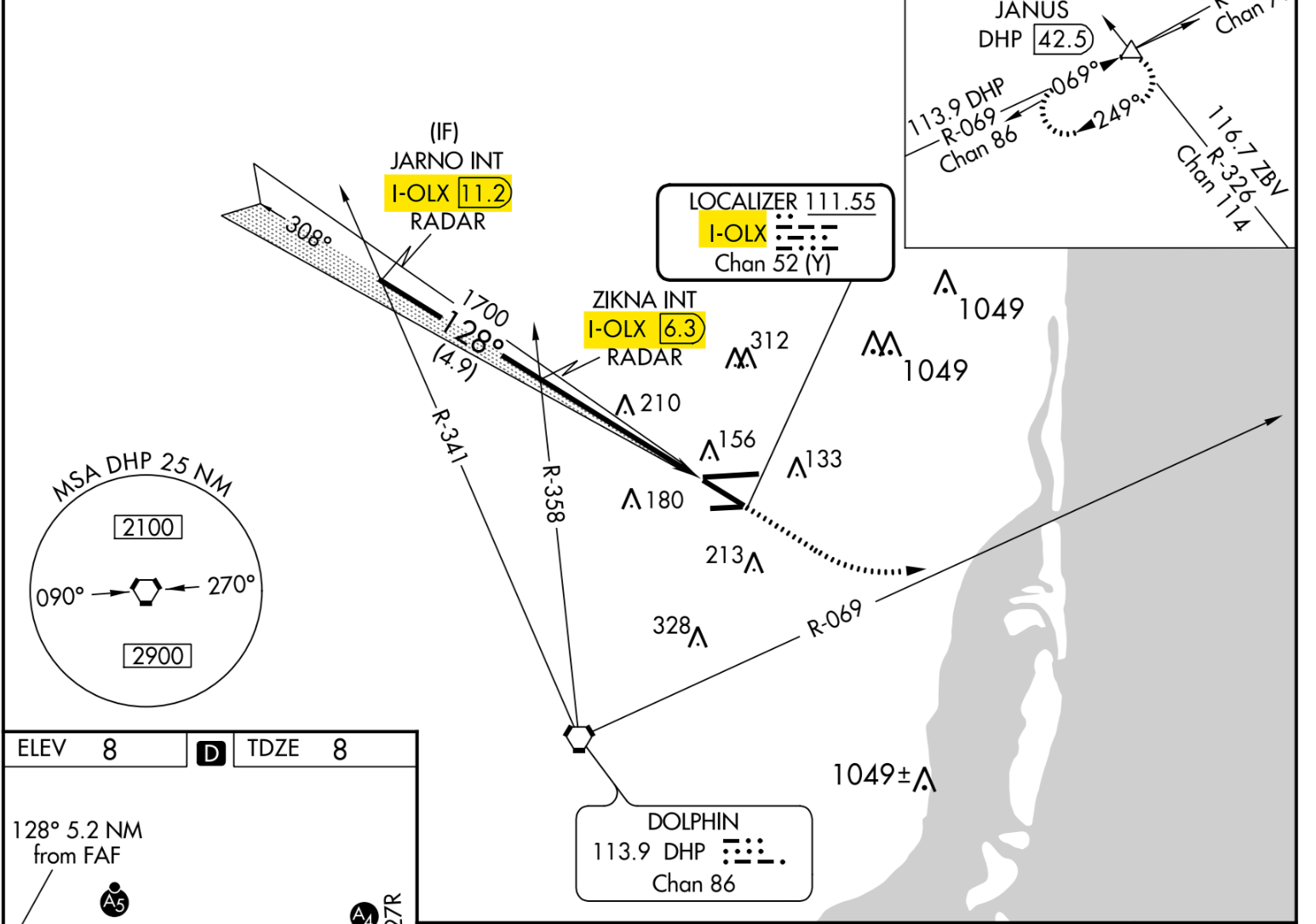
- If radar is available, you can receive vectors to the final approach course.
- ILS approach procedures can have straight-in (NoPT) initial approach segments to enable you to fly the approach without a course reversal.
Preparing the Approach
- Preparation starts with pre-flight actions. Check the arrival weather during flight planning and study the different types of approaches that may be used.
- After ATC informs you of the approach to expect, brief the details of the approach procedure.
Approach Overview
- The Approach Overview is the initial review of the expected approach procedure.
- Determine the factors that will affect the ability to perform the approach ahead of time.
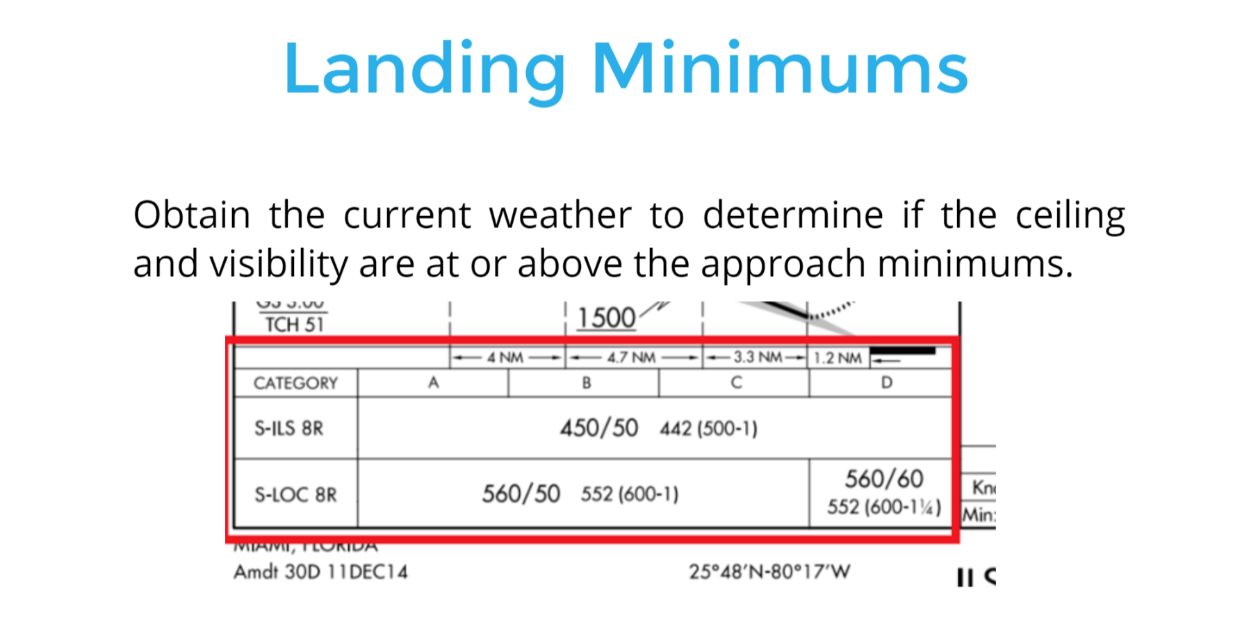
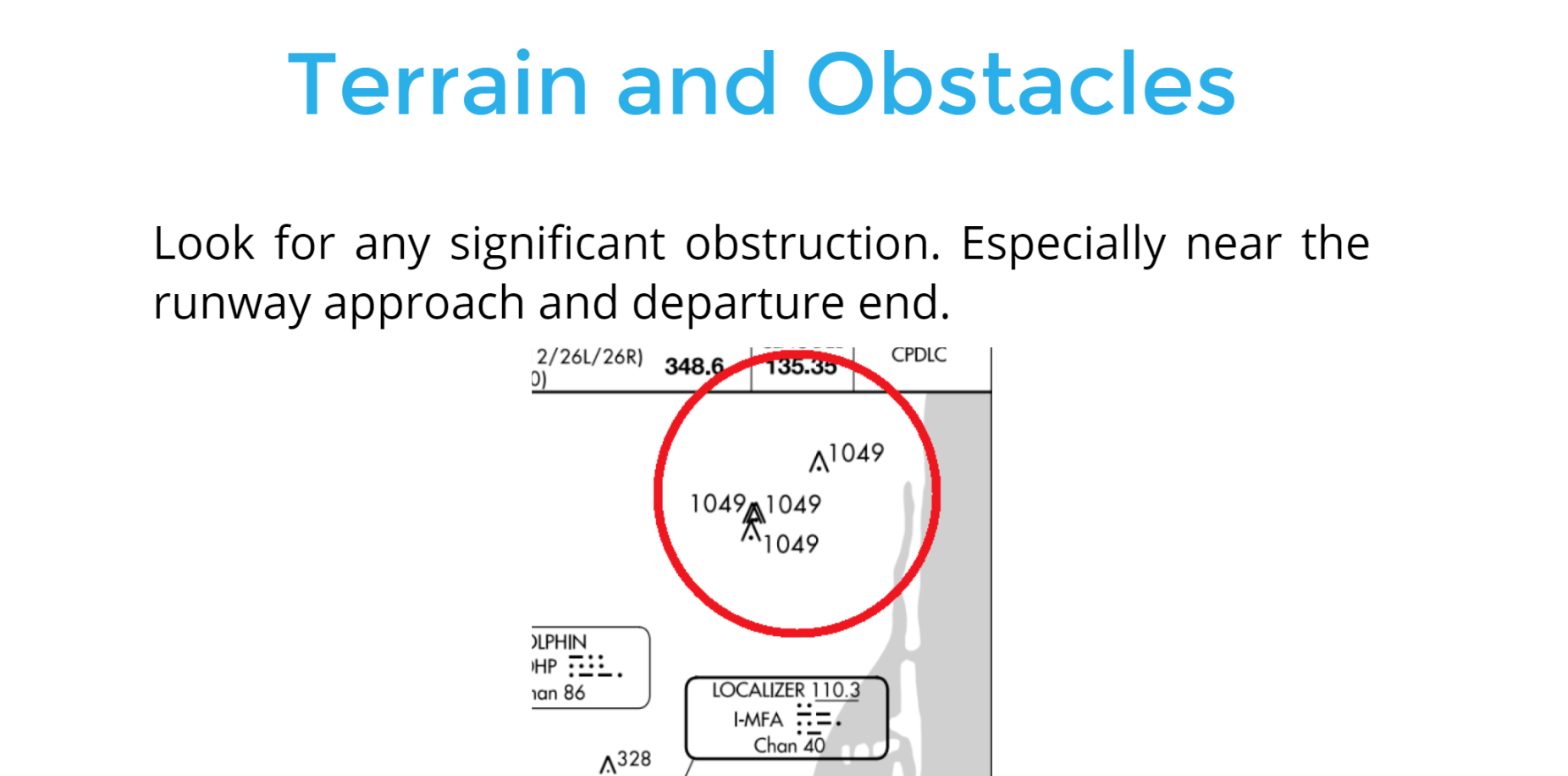
- Landing minimums, terrain, obstacles, and specific equipment are elements you should include.
2) Landing Minimums
1) Terrain and Obstacles
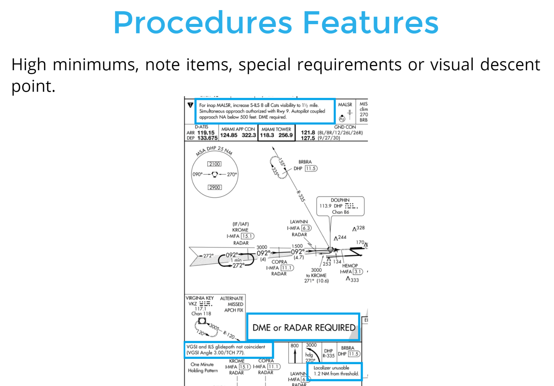
3) Procedures Features
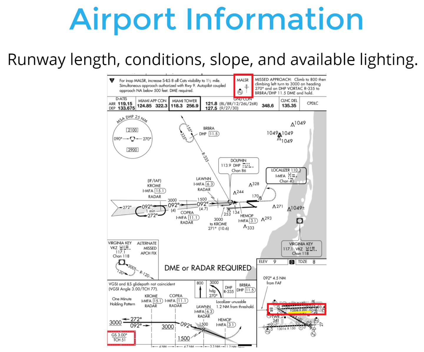
4) Airport Information
- Familiarize yourself with the approach after ATC has advised you the approach to expect.
- Check for specific approach procedure. Verbalize the primary elements of the approach.
Approach Briefing
Voice By: John Duque
Performing the Approach
ILS Approach with a Course Reversal
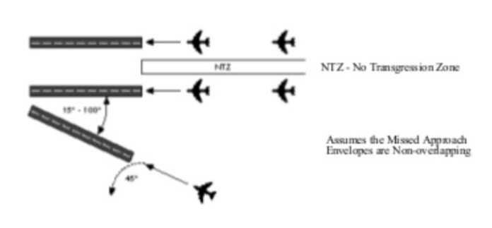
Simultaneous Approaches to Parallel Runways
ILS parallel approaches are divided into three classes depending on runway centerline separation.
Simultaneous Offset Instrument Approach
-
Allow simultaneous approaches to two parallel runways
- Runways should be separated at least 750 ft but less than 3,000 ft.
- When flying the offset approach, the airplane must be at the MAP to fly the visual on the segment to landing.
Simultaneous Converging Instrument Approach
- ATC may conduct instrument approaches simultaneously to converging runways; runways have an included angle of 15 to 100 degrees, at airports where a program has been specifically approved to do so.
- The basic concept requires that dedicated, separate standard instrument approach procedures be developed for each converging runway included. These approaches can be identified by the letter “V” in the title; for example, “ILS V Rwy 17 (CONVERGING)”.
- Other requirements are radar availability, non-intersecting final approach courses, and precision approach capability for each runway.
- Controllers must be able to apply visual separation as well as intersecting runway separation criteria.
- Intersecting runways also require minimums of at least 700-foot ceilings and 2 miles of visibility.
Localizer Approaches
- The localizer approach can be either performed if it's authorized to fly the ILS portion and use glide slope guidance.
OR
- Flying it as nonprecsion and use the localizer transmitter.
Localizer Approach
- A localizer approach is considered a Non-precision approach.
- The characteristics of the localizer are the same as those associated with an ILS approach. You fly the localizer using the same procedures to maintain the course as you would for an ILS.
Execute the missed approach upon reaching the missed approach point (MAP)
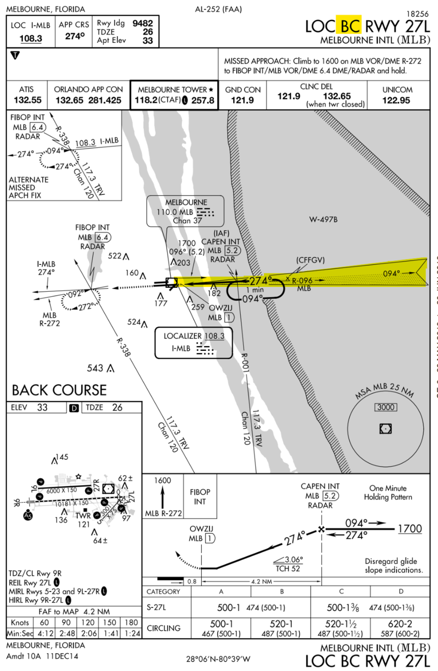
Localizer Back Course Approach
- Localizer back course approaches might be published.
- False glide slope signals might be received, do not follow them at any point during back course operations.
- Reverse sensing will occur when using a basic VOR indicator.
- HSI will avoid reverse sensing if the course is set on the OBS.
- Operation is the same as performing any other localizer approach.
Example
Localizer-Type Directional Aid
(LDA)
- The localizer-type directional aid (LDA) has comparable utility and accuracy to a localizer but is not part of a complete ILS.
- The difference between the LDA course and the LOC is that the LDA is not aligned with the runway.
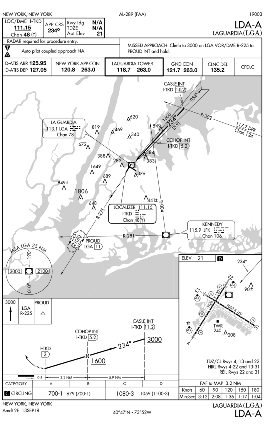
- The LDA course width is between 3° and 6°, and some are equipped with a GS.
- Minimums may be published where the angle between the runway centerline and the LDA course does not exceed 30°.
SDF Approach
- The simplified directional facility (SDF) provides a final approach course similar to the ILS localizer.
- The SDF course may or may not be aligned with the runway, and the course may be wider than a standard ILS localizer, resulting in less precision.
- Usable off-course indications are limited to 35° on either side of the course centerline.
- Instrument indications in the area between 35° and 90° from the course centerline are not controlled and should be disregarded.