GL 2 Flight Instruments

Rev 01/2025
Disclaimer
Students should use their textbooks, syllabus, and Airman Certification Standards (ACS) as their primary sources of information. EcFlight is an online training tool designed to simplify and enhance your ground school learning experience. However, it is not a substitute for FAA- or school-approved study materials. Before using these slides for study, always refer to your officially approved resources, such as the Jeppesen physical or electronic book and other FAA-approved materials.
Reference Books
-
Pilot's Handbook of Aeronautical Knowledge(FAA-H-8083-25B). (2016). Oklahoma City, OK: United States Department of Transportation, Federal Aviation Administration, Airman Testing Standards Branch.
-
Instrument Flying Handbook faa-h-8083-15B. (2012). Oklahoma City, OK: United States Department of Transportation, Federal Aviation Administration, Airman Testing Standards Branch.
- Instrument Pilot Syllabus (10001785-003). (2015). Englewood, CO: Jeppesen
- https://www.faa.gov/regulations_policies/handbooks_manuals/aircraft/amt_airframe_handbook/media/ama_ch10.pdf
- Cessna. (1976). Pilot's Operating Handbook(D1057-13). Wichita, KA: Cessna.
- Garmin. (2019). Garmin G3X Pilot's Guide. https://static.garmin.com/pumac/190-01115-00_q.pdf
Reference Multimedia
- ERAUSpecialVFR. (n.d.). Motion picture Embry-Riddle Aeronautical University. (n.d.) Retrieved from https://daytonabeach.erau.edu/.
- https://1.bp.blogspot.com/-MxqVDuUYOw0/UoejNvVaTbI/AAAAAAAABYg/o8FOD_5z-Ns/s1600/Typical+location+of+the+air+induction+and+exhaust+systems+of+a+normalizing+turbocharger+system.jpg
- https://www.championaerospace.com/wp-content/uploads/2015/06/Magneto31.jpg
- 1.bp.blogspot.com/_8U8aBVPO26Y/TPHj8Br5LkI/AAAAAAAAAGg/Rx1tUg-yYCs/s1600/C172_インダクションシステム(2).jpg.
- cessnaowner.org/wp-content/uploads/2015/05/DSCN0314-1024x768.jpg.
- Google Search, Google, www.google.com/search?q=piper arrow&safe=active&rlz=1C5CHFA_enUS806US806&source=lnms&tbm=isch&sa=X&ved=0ahUKEwj2nYHBqtvhAhUDO60KHVkZAdgQ_AUIDigB&biw=1440&bih=740#imgdii=qVlt1FGEDFSYXM:&imgrc=7HBMk4FqeotaAM:
- www.ctsys.com/images/easyblog_articles/43/Fuel01.jpg.
- Aviation, U. (2017). Electrical system of aicraft. Retrieved from https://aviationglossary.com/loadmeter/
- Can we get flexible static wicks for our Mooneys (2017). Retrieved from https://mooneyspace.com/topic/22908-can-we-get-flexible-static-wicks-for-our-mooneys/
- https://static1.simpleflyingimages.com/wordpress/wp-content/uploads/2023/02/shutterstock_690836215-1.jpg?q=50&fit=contain&w=1140&h=&dpr=1.5
- https://defineaviation.info/wp-content/uploads/The-Magnetic-Compass-of-an-Aircraft3-604x270.jpg
- https://static.garmin.com/pumac/190-01115-00_q.pdf
- https://www.flyhpa.com/files/2013/02/2015.04.10-01.44-flyhpa-55272af302764.png
- https://cdn.shopify.com/s/files/1/0403/2205/products/G3X-Touch-AOA.jpg?v=1395849627
- Pilot's Handbook of Aeronautical Knowledge(FAA-H-8083-25B). (2016). Oklahoma City, OK: United States Department of Transportation, Federal Aviation Administration, Airman Testing Standards Branch.
- https://www.flyhpa.com/files/2011/09/2015.04.10-01.35-flyhpa-552728de3803d.jpg
- https://images.flyingmag.com/flyingma/wp-content/uploads/2021/08/30200716/httpswww.flyingmag.comsitesflyingmag.comfilesimport2014sitesallfiles_images201409G1000-fix-rotator.jpg
Reference Videos/Animations and Blogs
- ERAUSpecialVFR. (n.d.). Motion picture.
- https://www.experimentalaircraft.info/articles/aircraft-vacuum-gyro-system.php
- https://www.grc.nasa.gov/www/k-12/airplane/move.html
- https://www.youtube.com/watch?v=gCq3EjF1iZ4
- HERSTAM, J. (2023, February 11). What is a flight director & how do they work? Simple Flying. https://simpleflying.com/flight-director-guide/
- Turner, T. (2019, October 29). Glass Cockpit Partial Panel. Aviation Safety. https://www.aviationsafetymagazine.com/features/broken-glass/
Index

Analog Flight Instruments
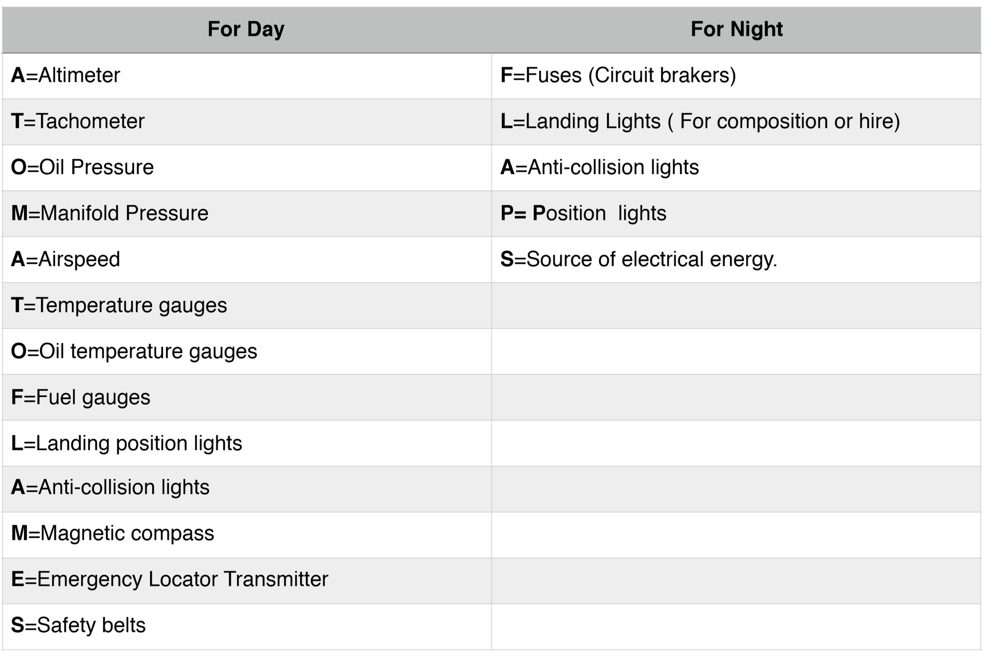
Instruments For Flight Under IFR
FAA Instrument Requirements FAR § 91.205 (d)
G
R
D
C
B
A
A
D
R
enerator/Alternator
adio (Two way capabilities)
ttitude Indicator
all (Inclinometer)
lock (Displays Hours,Minutes,Seconds)
ltimeter (Sensitive altimeter)
ate of turn indicator
irectional Gyro (Heading indicator)
ME (Above FL240)
For IFR flight, the following instruments and equipment are required
Instruments and equipment specified in paragraph (b) and (c) of 91.205 are also required.
Click Here 91.205 (b)(c)
Inspection Requirements
FAR § 91.409
Airworthiness directives
VOR (30 Days)
Altimeter and Static Pressure system ( 24 calendar months )
Transponder ( 24 calendar months )
Inspection Annual inspection (A&P with IA)100 hours inspection (A&P)
ELT (12 calendar months ) and change the battery when 1 hour accumulated use or 50% of battery life
A
V
I
A
T
E
Gyroscopic Flight Instruments
Attitude Indicator
Heading Indicator
Turn Coordinator
What is a Gyro?
How Does it Work?
A Gyro is a heavily shining disc that is able to maintain its position and orientation
How Does it Work?
There are two fundamental properties of a gyro:
- Rigidity in space
- Precession
What is a Gyro?
Rigidity In Space
- Rigidity in space refers to the principle that a gyroscope remains in a fixed position in the plane in which it is spinning.
- By mounting this gyroscope, on a set of gimbal rings, the gyro is able to rotate freely in any direction.
Precession
- Precession is the tilting or turning of a gyro in response to a force.
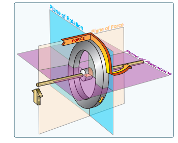
- The reaction to this force occurs at a point that is 90° later in the direction of rotation.
- This will cause small Errors in the Instruments
Powered
Attitude Indicator and Heading Indicator are Air Vacum Driven
Turn Coordinator is Electric driven
Vacuum System
In simple, The engine driven pump sucks air through the system. The air flows in from the inlet filter, normally located under your instrument panel, directly into the inlet ports on your Attitude indicator and Heading indicator. The Suction Gauge give a differential pressure measured in Inches of Mercury.
Filter
Gyro
Vacuum Pump
Vacuum System
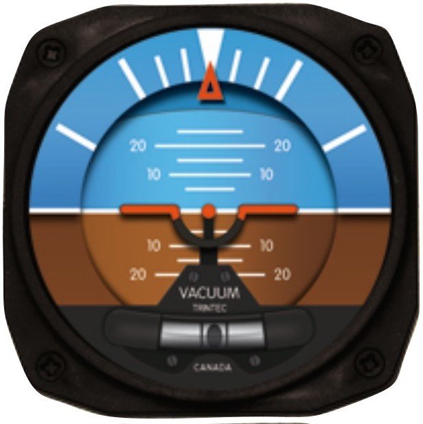
Attitude Indicator
Instrument Operation
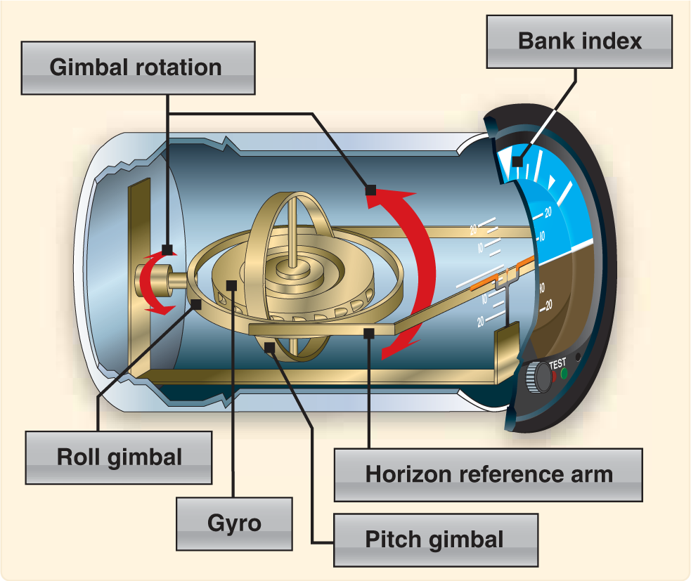
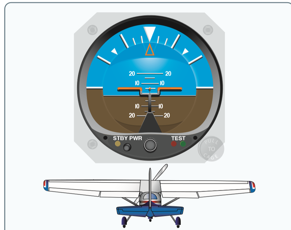
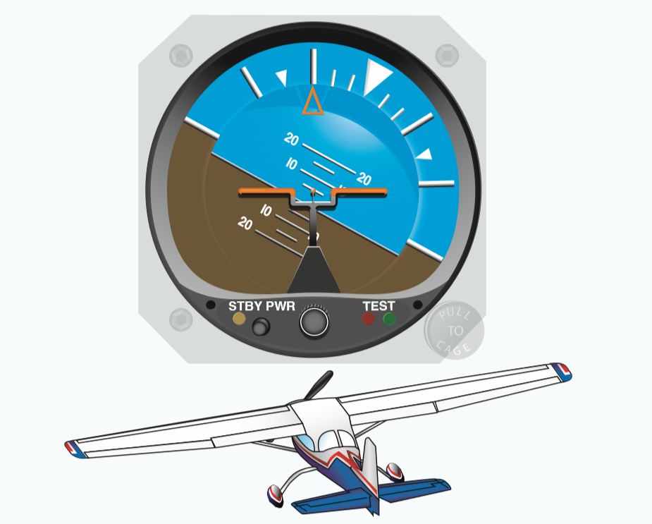
The gyro in the attitude indicator is mounted in a horizontal plane and depends upon rigidity in space for its operation. The horizon bar represents the true horizon.
- A small symbolic aircraft is mounted in the instrument case so it appears to be flying relative to the horizon. A knob at the bottom center of the instrument case raises or lowers the aircraft to compensate for pitch trim changes as the airspeed changes.

The gyro is mounted in a double gimbal, which allows the aircraft to pitch and roll about the gyro as it remains fixed in space.
- For the attitude Indicator to remain erect, it has a series of Pendulous vanes. They open and close by gravity to erect itself and correct for precession.
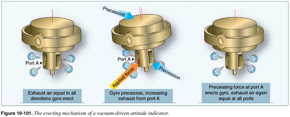
- Instrument Should be Up and Erect within 5 minutes. In addition, deviation no more than 5 degrees pitch and bank.
- If the Aircraft experience abrupt change in Pitch or bank may cause inaccurate readings.
-
Limits in the banking plane are usually from 100° to 110°, and the pitch limits are usually from 60° to 70°. If either limit is exceeded, the instrument will tumble or spill and will give incorrect indications until realigned
Limitations / Instrument Check
Instrument Errors
Attitude indicators are free from most errors, but there may be a slight nose-up indication during a rapid acceleration and a nose-down indication during a rapid deceleration.
Turning: When initiating a turn the gyro will swing or move to the rear, again due to precession of centrifugal force against the gyro. both errors are small and will correct themselves.
- These inherent errors are small and correct themselves within a minute or so after returning to straight-and-level flight and are less than half bar width.
- Suction: When suction falls below 3 1/2 inHg, the instrument will become sluggish to move. Above 4 1/2 inHg, the attitude indicator will become more lively, and it will wear out that much sooner.
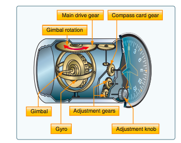
Heading Indicator
Instrument Operation
- The operation of the heading indicator depends upon the principle of rigidity in space. The rotor turns in a vertical plane and fixed to the rotor is a compass card.
- The gyro in a heading indicator is mounted in a single gimbal, spins in a vertical plane as the aircraft rotates around the gryo.
- Gyro heading indicators, with the exception of slaved gyro indicators, are not north seeking, therefore they must be manually set to the appropriate heading by referring to a magnetic compass.
The Earth constantly rotates at 15° per hour while the gyro is maintaining a position relative to space, thus causing an apparent drift in the displayed heading of 15° per hour.

Instrument Check
- While taxiing, the instrument should indicate turns in the correct direction.
Instrument Errors
- Because of precession, caused by friction between the gyro and gimbals, the heading indicator drifts from its set position.
- The heading indicator may indicate as much as 15° error per every hour of operation. Is recommended to check it every 15 minutes.
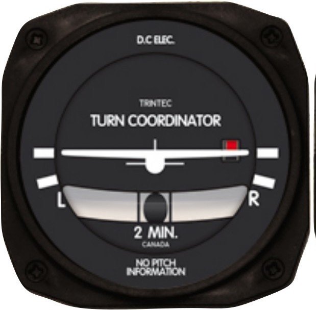
Turn Coordinator
System Operation
- Indicates the Rate of roll and Rate of turn.
- The gimbal in the turn coordinator is inclined; therefore, its gyro can sense both rates of roll and rate of turn.
Gyro Click Here
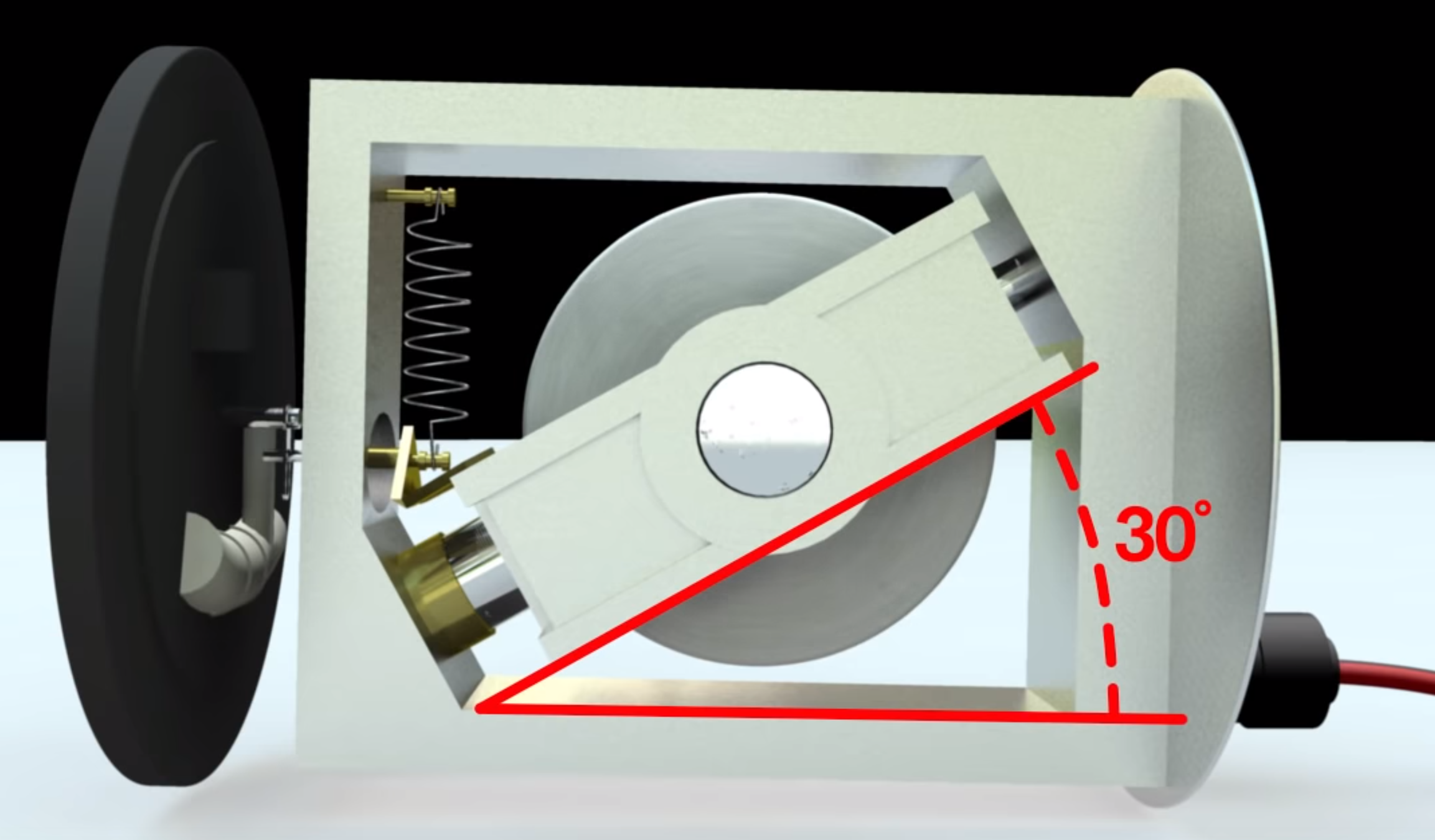
- A standard-rate turn is defined as a turn rate of 3° per second.
Angle Of Bank = (KTAS / 10) + 5
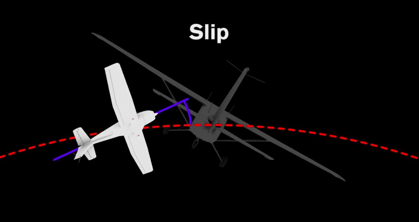
If inadequate right rudder is applied in a right turn, a slip results. Too much right rudder causes the aircraft to skid through the turn. Centering the ball results in a coordinated turn.
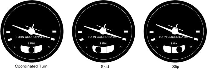
SLIP
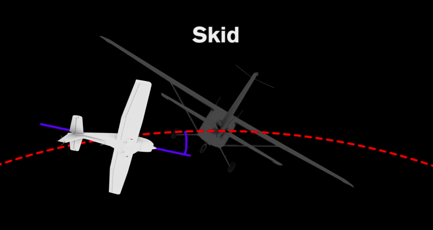
SKID
- During a slip there's not enough rate of turn for the amount of bank
- Pilot need to increase the amount of rudder input.
- During a Skid there's to much rate of turn for the amount of bank
- Pilot need to decrease the amount of rudder input.
- During pre-flight, ensure that the inclinometer is full of fluid and has no air bubbles.
- The ball should also be resting at its lowest point.
- When taxiing, the turn coordinator should indicate a turn in the correct direction while the ball moves opposite the direction of the turn.
Instrument Check
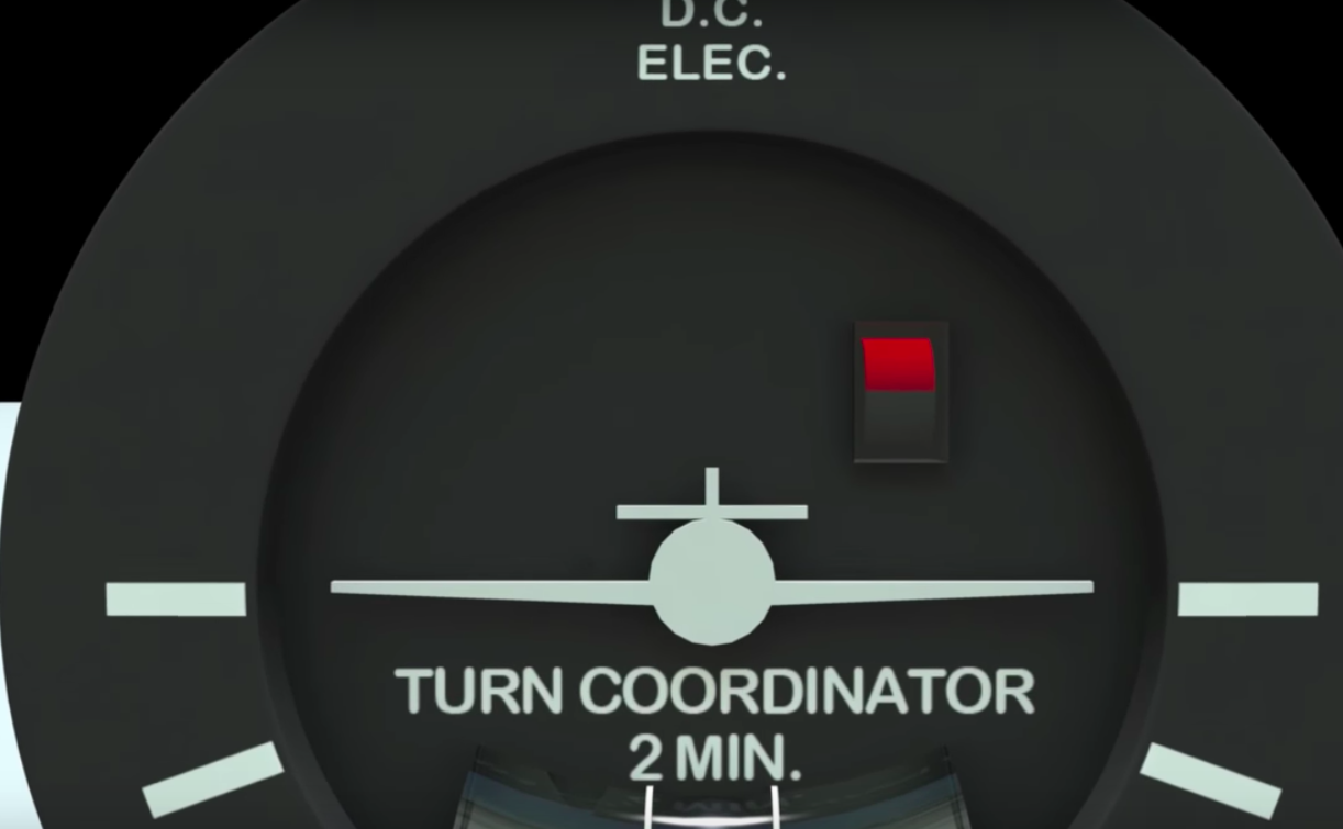
- For an electric turn coordinator, the main failure modes will be an electrical failure
System Error
- A red flag shows the instrument is in a non-operational status
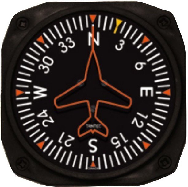
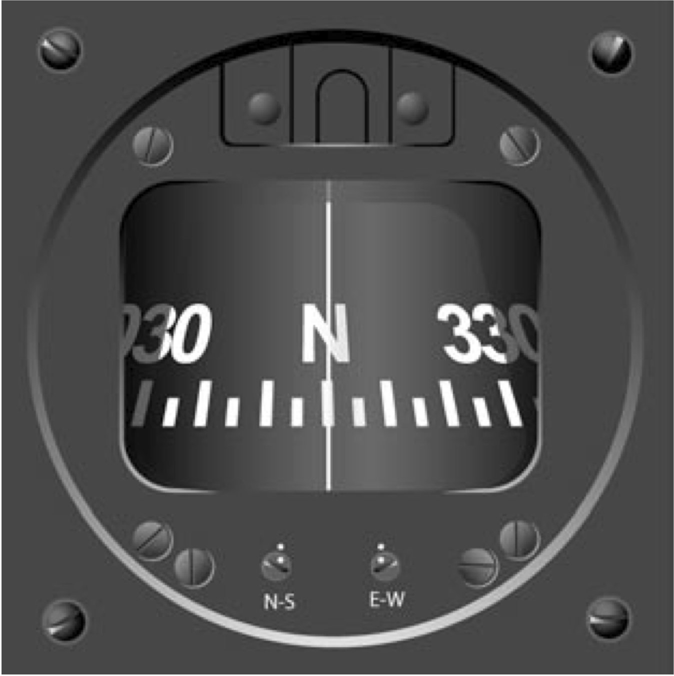
Magnetic Compass
- One of the oldest and simplest instruments for indicating direction.
- A self-contain instrument that does not require electricity or any other mechanism to work.
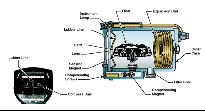
Instrument Operation
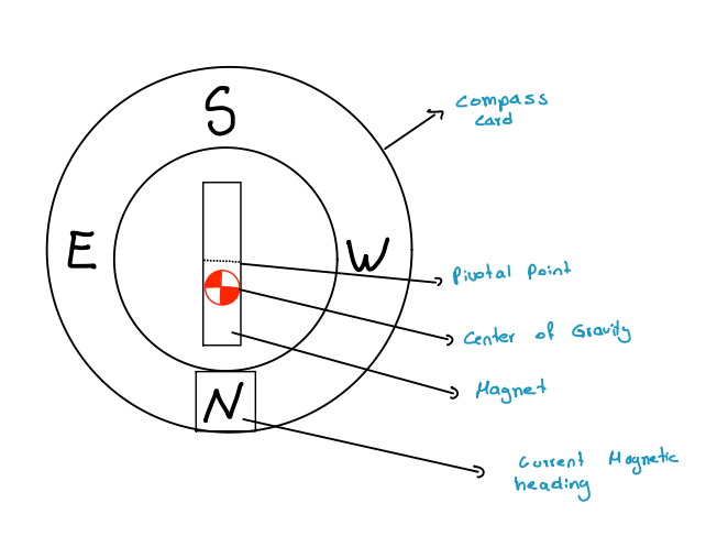
- Has two small magnets attached to a metal float sealed inside a bowl of clear compass fluid similar to kerosene.
- Magnets are mounted to float, so they move freely and align with the Earth's magnetic field.
- A graduated scale, called a card, is wrapped around the float and viewed through a glass window with a lubber line across it
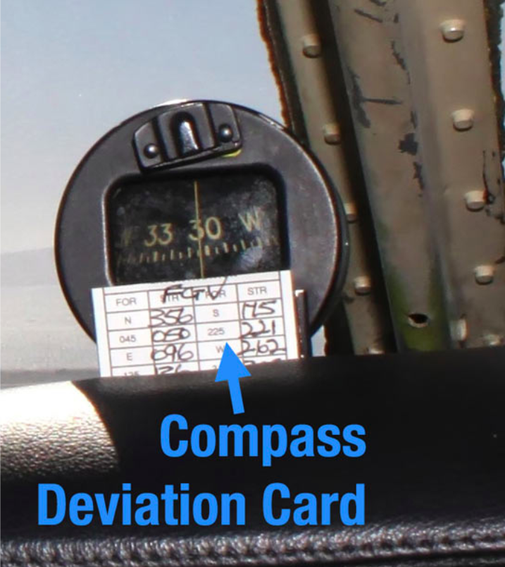
Instrument Check

- Verify compass is full of fluid, moving freely, turning, and indicating in the proper known direction.
- Check for the compass correction card.
Instrument Errors
D
V
M
O
N
A
Deviation
Variation
Magnetic Dip
Oscillation
Northerly Turning Error
Acceleration Error
Deviation
The deviation is caused due to disturbances from other magnetic and electrical objects within the airplane itself.
An aviation maintenance technician (AMT) can minimize deviation error by performing the maintenance task known as “swinging the compass," once this procedure is complete and compass adjust. The AMT records any remaining error on a compass correction card like and places it in a holder near the compass.
Variation
- Angular Difference Between Magnetic North and True North
Oscillation
- Oscillation is caused by fluctuation of the compass during turbulence.
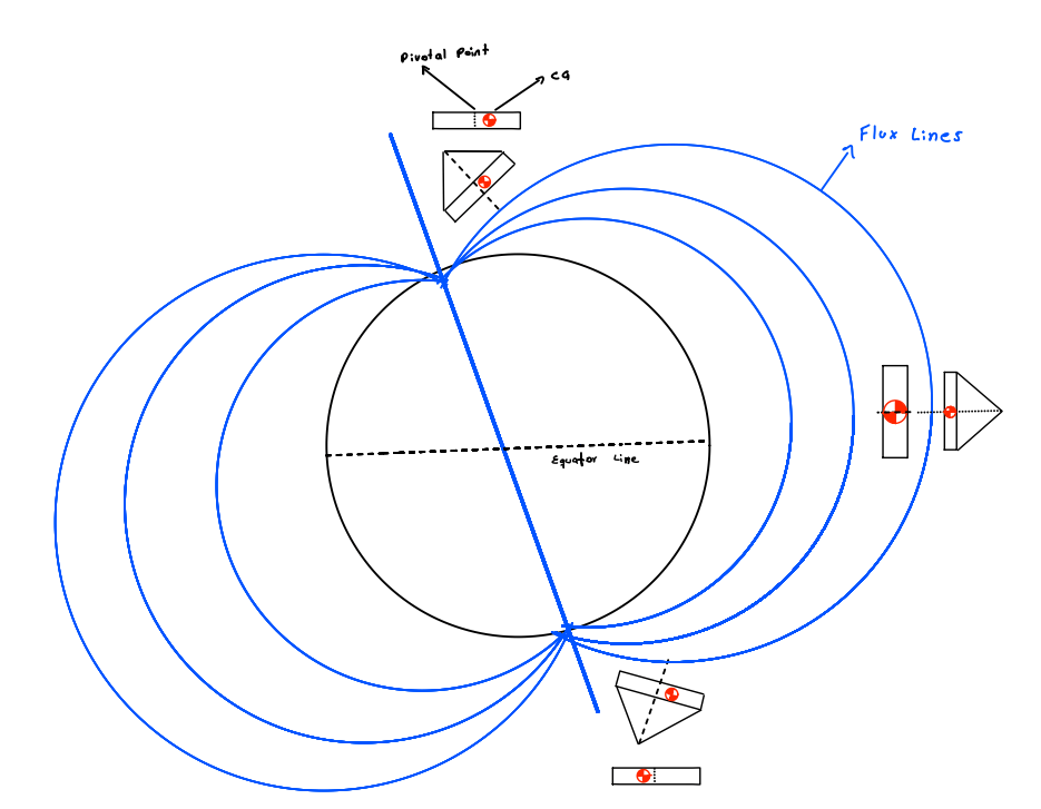
Magnetic Dip
- Earth's Magnetic Fields are located deep inside the planet.
- This will create the tendency of the compass to point down. The dip angle increases in a downward direction as you move towards the Magnetic North Pole and increases in an upward direction as you move towards the Magnetic South Pole.
- On the equator line, the magnetic compass's center of gravity (CG) and its pivotal point are aligned since the flux lines are parallel to it. However, close to the poles, the magnetic compass tilts due to the magnetic flux lines, causing the magnetic compass CG to move and consequently induce acceleration/deceleration and northerly/southerly turning errors.
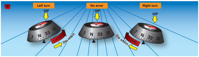
Northerly Turning Error
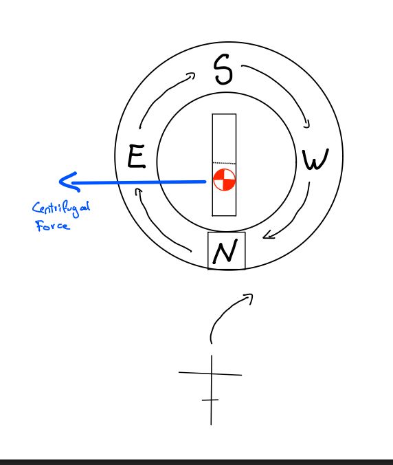
- The center of gravity of the float assembly is located lower than the pivotal point. As the airplane turns, the force that results from the magnetic dip causes the float assembly to swing in the same direction that the float turns. The result is a false northerly turn indication.
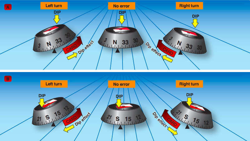
- When heading north in the northern hemisphere, if the aircraft turns either west or east, the magnet CG goes out of the turn due to centrifugal force. As this happens, the compass card also moves (remember it is suspended in liquid), showing a momentary turn in the opposite direction. Eventually, it will display the correct heading.
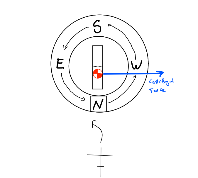
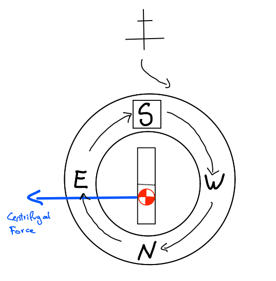
- When heading south in the northern hemisphere, if the aircraft turns either west or east, the magnet CG goes out of the turn due to centrifugal force. As this happens, the compass card also moves, showing a faster than normal turn in the same direction. Eventually, it will display the correct heading.
U
N
O
S
Remember
Undershoot
North
Overshoot
South
- Stop Turn = Latitude +/- half Bank Angle
General rule:
- This only applies in the northern hemisphere.
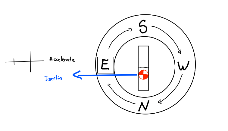
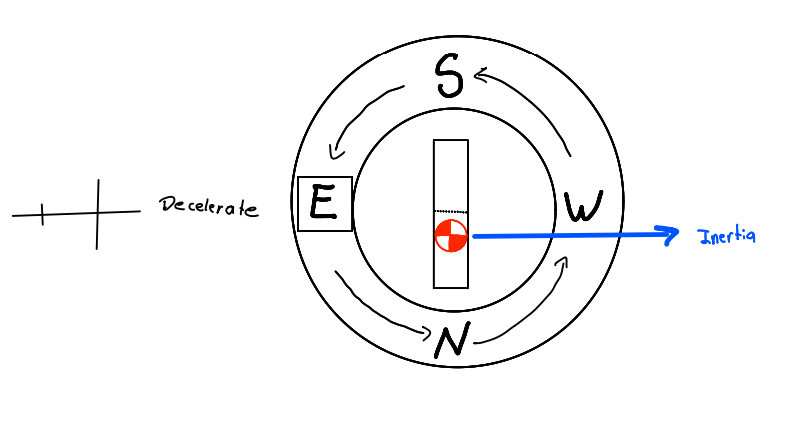
Acceleration / Deceleration Error
- The magnetic dip and the forces of inertia cause magnetic compass errors when accelerating and decelerating on easterly and westerly headings.
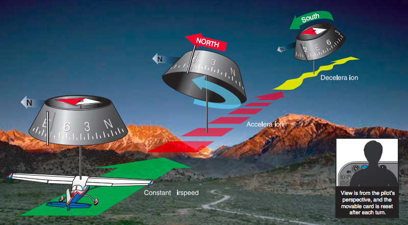
- This error occurs only when heading east or west.
- If the aircraft accelerates on heading east or west, the inertia will make the magnet CG move backward, subsequently rotating the compass card and showing a momentary turn to the north. Eventually, it returns to the correct heading.
- If the aircraft decelerates on a heading east or west, the inertia will cause the magnetic center of gravity to move forward, subsequently rotating the compass card and showing a momentary turn to the south. Eventually, it returns to the correct heading.
A
N
D
S
Accelerate
Decelerate
North
South
Remember
- This only applies in the northern hemisphere.
Pitot Static Instruments
- Altimeter Airspeed Indicator Vertical speed indicator
- The pitot-static system is a combined system that utilizes the static air pressure (static port) and the dynamic pressure (pitot tube) due to the motion of the aircraft through the air.
The pitot tube is utilized to measure the total combined pressures that are present when an aircraft moves through the air. Called dynamic pressure or ram air pressure
Pitot Tube
Click Here
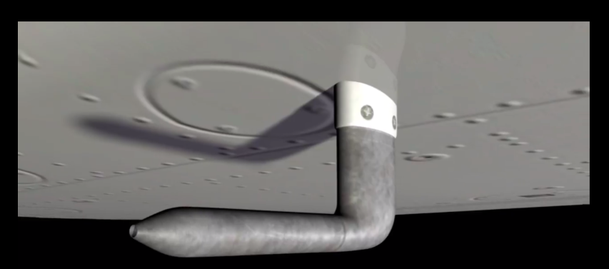
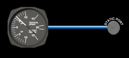
Static Port
Click Here
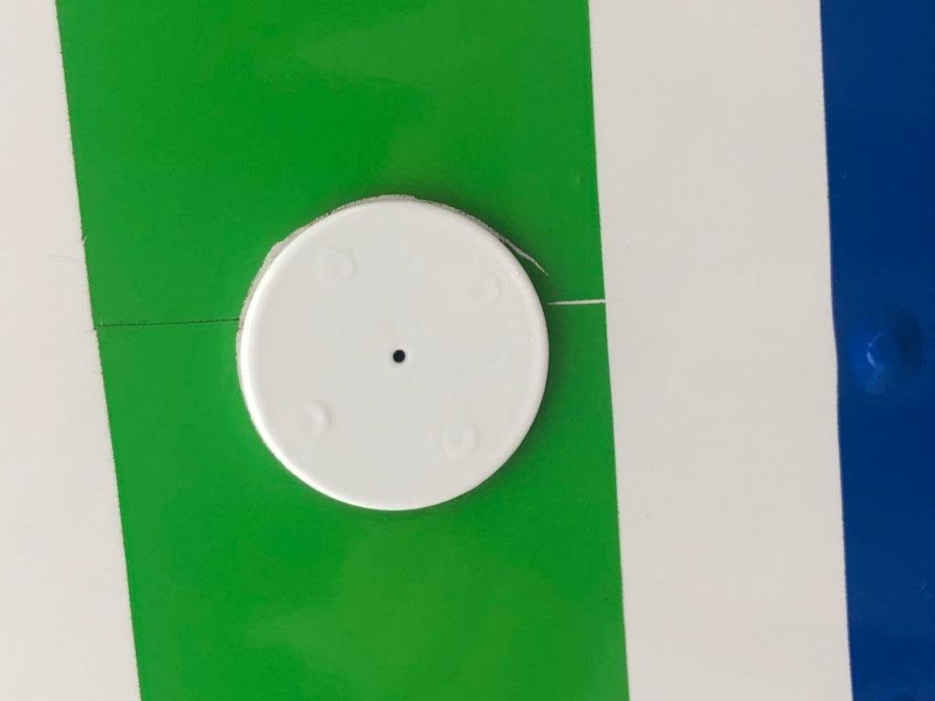
Measure the static pressure, also known as ambient pressure, Located where there's almost no Interference with Air surround for accuracy.
- These combined pressures are utilized for the operation of the airspeed indicator (ASI), altimeter, and vertical speed indicator (VSI).
-
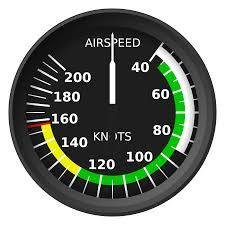
Uses ram air pressure from the pitot tube and the static pressure from the static port.
-
Displays airspeed change in Knots.
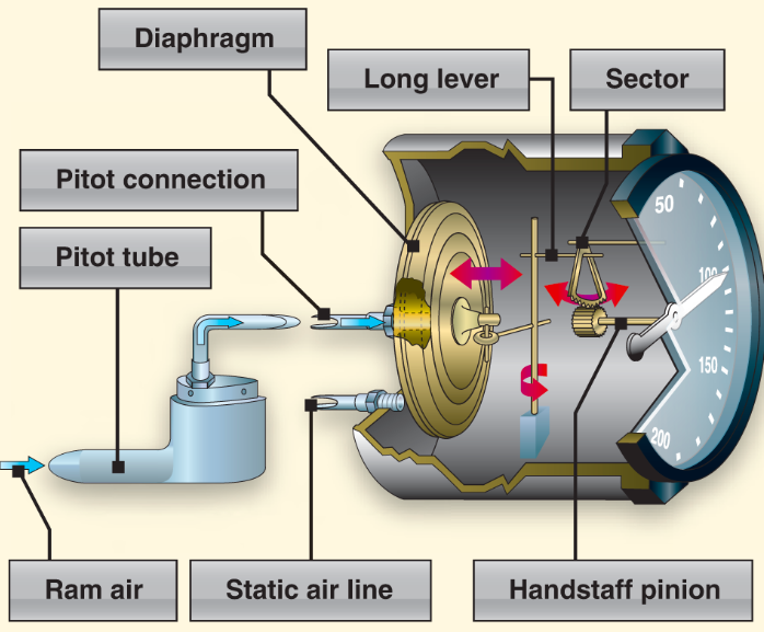
A diaphragm receives ram air coming from the pitot tube, then expands or contracts against the static pressure to display the aircraft's airspeed.
Animation by ERAU
Review
Types Of Airspeeds
Indicated Airspeed
Calibrated Airspeed
Equivalent Airspeed
True Airspeed
Ground Speed
As a pilot you need to become familiar with the different types of airspeed.
Indicated Airspeed
Indicated airspeed (IAS)—the direct Airspeed reading obtained from the Instrument.
Calibrated Airspeed
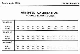
-
Calibrated airspeed (CAS)- is indicated airspeed corrected for Instrument installation.
-
Manufacturers attempt to keep airspeed errors to a minimum.
True Airspeed

True airspeed (TAS)- calibrated airspeed corrected for altitude and nonstandard temperature.
At sea level on a standard day, CAS is equal to TAS.
Ground Speed
-
True airspeed adjusted for wind, actual speed of the airplane over the ground.
-
Ground airspeed decreases with a headwind and increases with a tailwind.
Mach Speed
- Mach is the ratio of the aircraft true airspeed to the speed of sound.
- Example: .8 Mach = 80% of the speed of sound
Instrument Check
- When the airplane is not moving airspeed should read 0.
- When taking off airspeed should move as the airplane accelerates on the runway.
Instrument Error
- Pitot tube blocked
- Ram air blocked
- Static port blocked
- Cold temperature: IAS lower than TAS
- Warm temperature: IAS higher than TAS
V-Speeds and Color Codes
V-Speeds
| VS0 | Stall speed in landing configuration | |
| VS1 | Stall speed in clean configuration | |
| VFE | Maximum speed - Flaps extended | |
| VNO | Maximum structural cruising speed | |
| VNE | Never exceed speed |
Additional V-Speeds
| VX | Best angle climb speed | |
| VY | Best rate climb speed | |
| VA | Maneuvering speed | |
| VFE-10° | Maximum speed - Flaps 10° Flaps extended | |
| VG | Best glide speed |
| VR | Rotation speed |
| VREF | Reference landing approach speed |
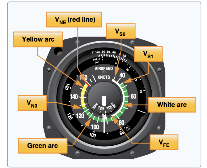
V-Speeds Color Codes
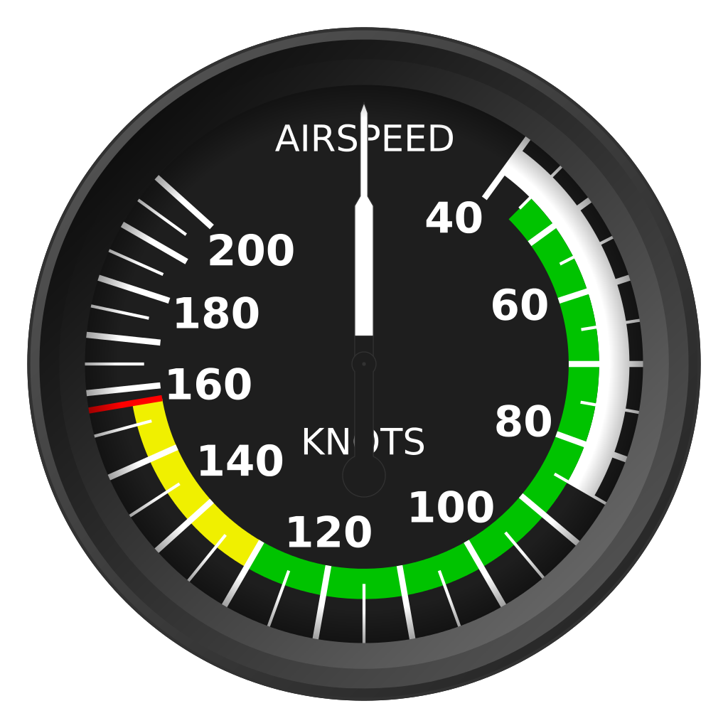
White arc:
flap operating range
Green arc: normal operating range
Yellow arc: “caution range”
Red line:
never exceed speed
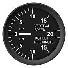
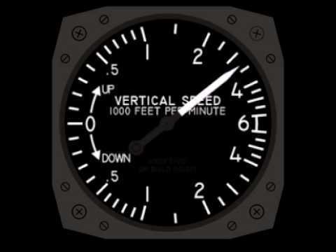
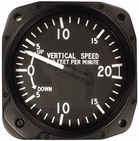
Vertical Speed Indicator
Indicates whether the aircraft is climbing, descending, or in level flight. The rate of climb or descent is indicated in feet per minute (fpm). Uses information only from the Static Port.
System Operation
Displays two different types of information:
- Rate Information
- Trend information.
Trend information shows an immediate indication of an increase or decrease in the aircraft’s rate of climb or descent.
Rate information shows a stabilized rate of change in altitude.
It contains a diaphragm with connecting linkage and gearing to the indicator pointer inside a case.
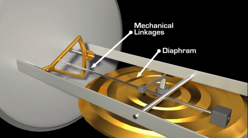

The inside of the diaphragm is connected directly to the static line of the pitot-static system.
Animation by ERAU
Calibrated Leak
The area outside the diaphragm, which is inside the instrument case, is also connected to the static line but through a restricted orifice (calibrated leak).
Animation by ERAU
When the aircraft climbs or descends, the pressure inside the diaphragm changes immediately, but due to the calibrated leak, the case pressure remains higher or lower for a short time, causing the diaphragm to contract or expand.
Animation by ERAU
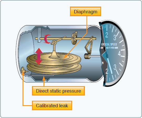
If the pitch attitude is held constant, the needle stabilizes after a short period (6–9 seconds) and indicates the rate of climb in hundreds of fpm. The time period from the initial change in the rate of climb, until the VSI displays an accurate indication of the new rate, is called the lag.
Instrument Check
Before engine start, the VSI should read 0. If not, use the reading as it is level.
Instrument Error
Sudden or abrupt changes in aircraft attitude cause incorrect instrument readings as the air flow fluctuates over the static ports. Delay from 6-9 seconds.
Pitot System Blockage
Pitot Tube Blockage
-
Airspeed: If the pitot tube is clogged but drain hole is open, Indicated airspeed drops slowly to zero because of ram air is no longer able to enter the pitot system. Air already in the system vents through the drain hole, and the remaining pressure drops to ambient (outside) air pressure.
-
If the pitot tube ram pressure hole and drain hole become obstructed, the ASI operates like an altimeter as the aircraft climbs and descends.
-
Altimeter and VSI will continue working.
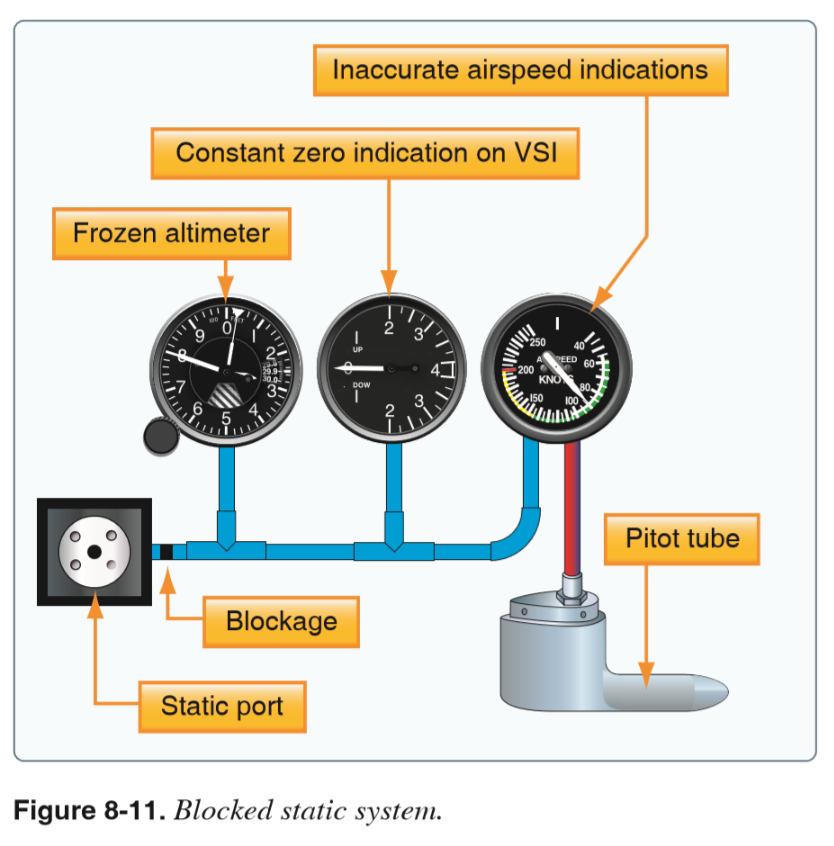
Static Port Blockage
If the static port block but pitot is clear:
-
The Airspeed Indicator is inaccurate because of the trapped static pressure inside the case.
-
The Altimeter freeze at the altitude where the blockage occurred.
-
The VSI will indicate zero due to static pressure being vented through the calibrated leak
Using the Alternate Static Source
Opening the alternate static source introduces static pressure from the flight deck into the system. Flight deck static pressure is lower than outside static pressure.
When the alternate static source pressure is used, the following instrument indications are observed:
-
The altimeter indicates a slightly higher altitude than actual.
-
The Airspeed Indicator indicates an airspeed greater than the actual airspeed.
-
The VSI shows a momentary climb and then stabilizes if the altitude is held constant.
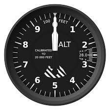
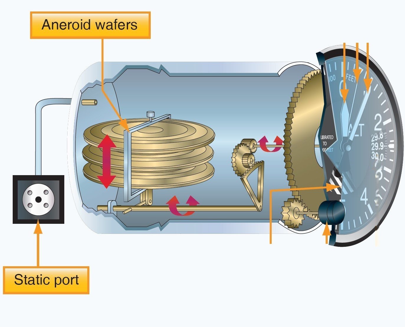
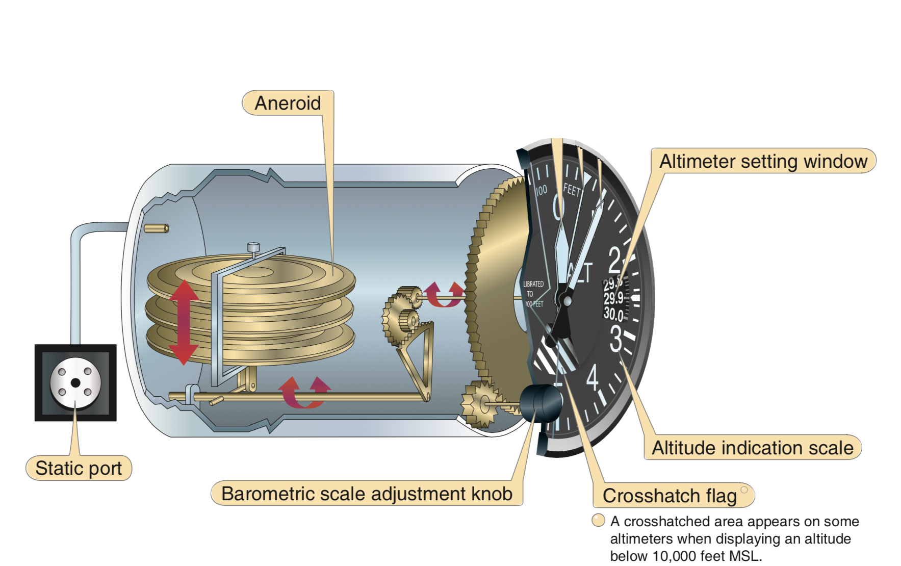
Altimeter
Instrument that measures the height of an aircraft above a given pressure level.
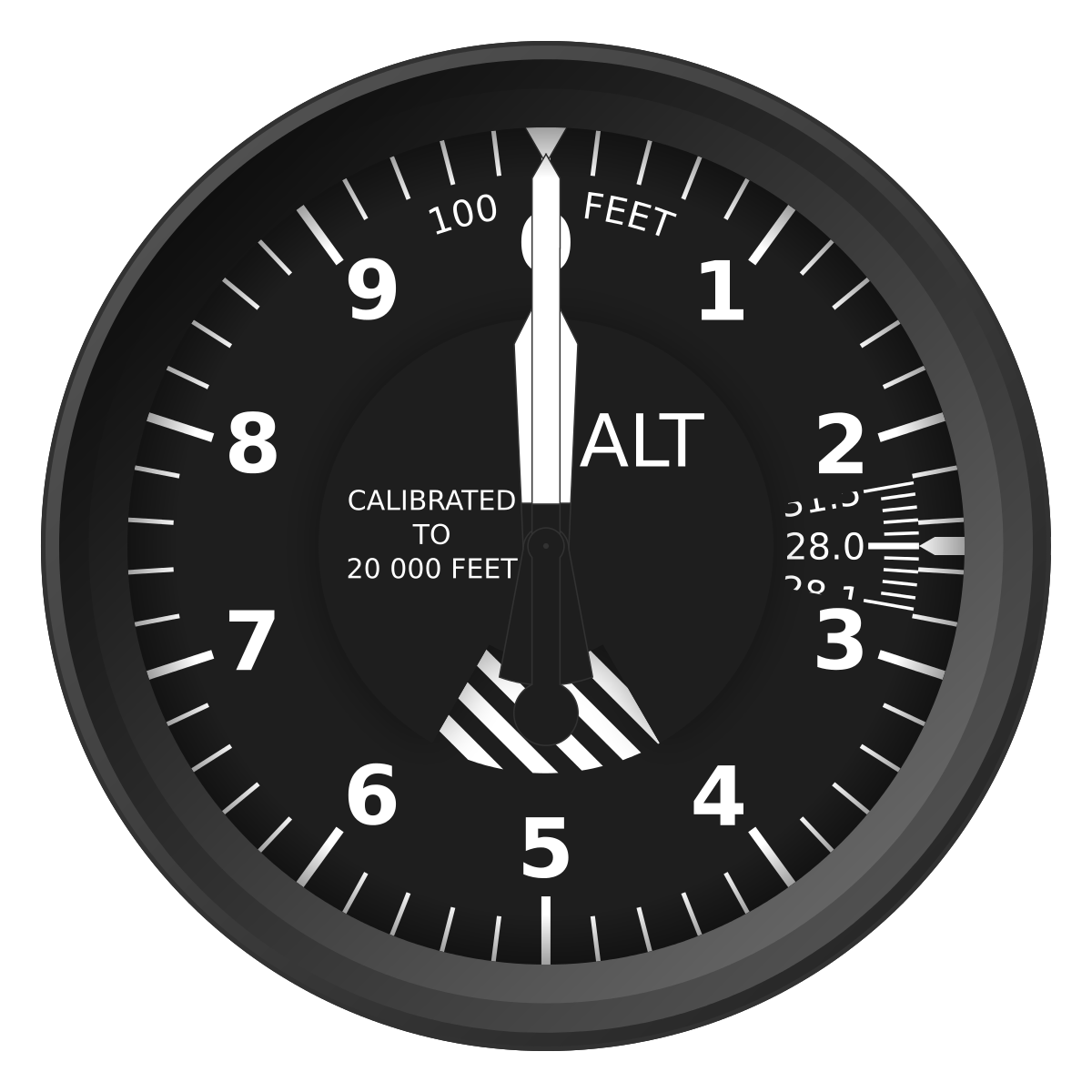
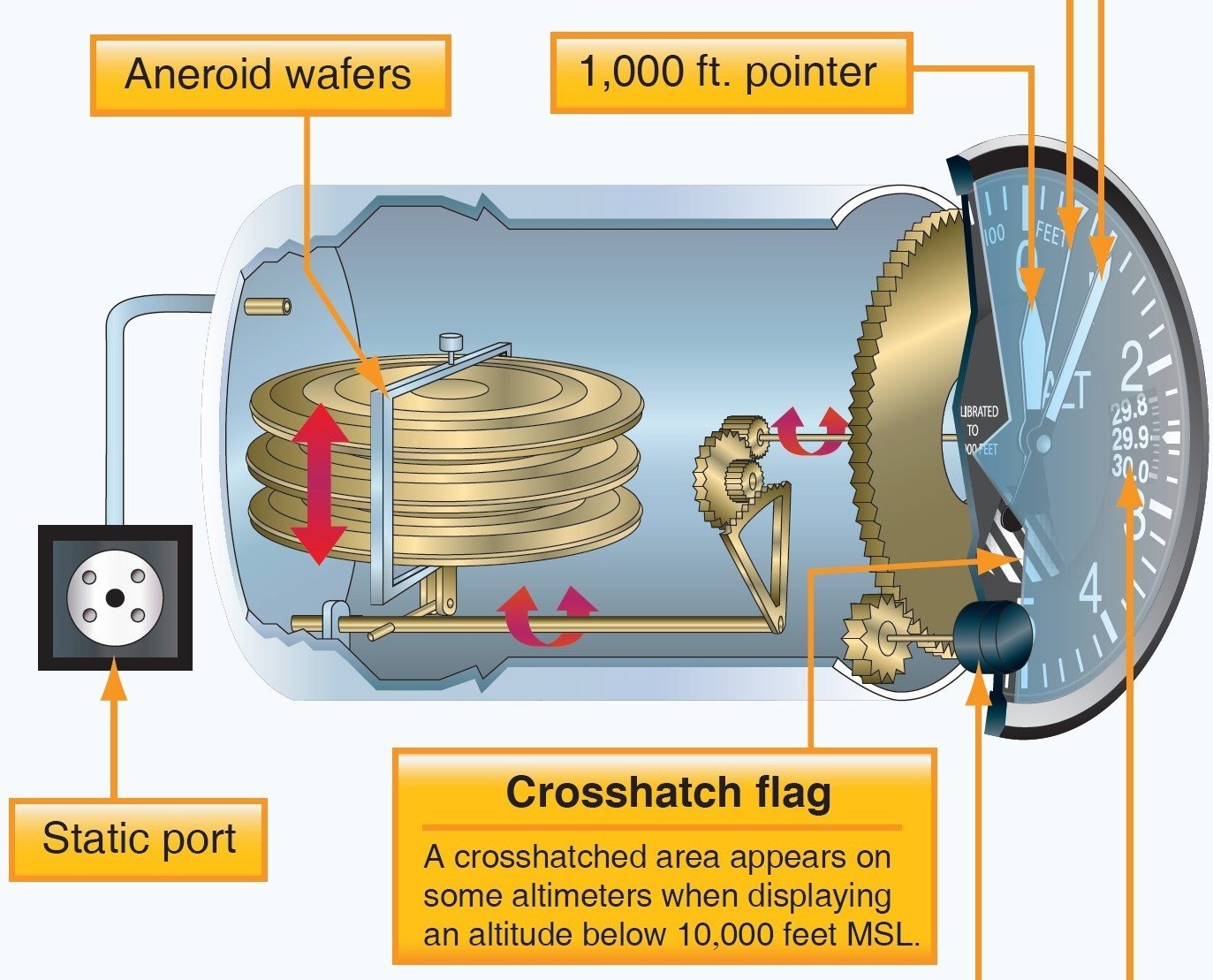
A sealed Aneroid wafers, with internal pressure of 29.92, is the main component of the altimeter. These wafers are free to expand and contract with changes to the static pressure.
What happens when the airplane climb or descend?
-
A higher static pressure presses down on the wafers and causes them to collapse. A lower static pressure (less than 29.92 "Hg) allows the wafers to expand.
Animation by ERAU
A mechanical linkage connects the wafer movement to the needles, which translates compression of the wafers into an increase or decrease in altitude
Types of Altitudes
Indicated Altitude
Pressure Altitude
Absolute Altitude
Density Altitude
True Altitude
Altitude is
Indicated Altitude
Altitude read directly from the altimeter (uncorrected) when it is set to the current altimeter setting.
Pressure Altitude
Pressure altitude is the height above a standard datum plane (SDP), which is a theoretical level where the weight of the atmosphere is 29.92 "Hg (1,013.2 mb) as measured by a barometer.
Formula: ( Standard Pressure - Current Pressure ) X 1000 +/- Field Elevation
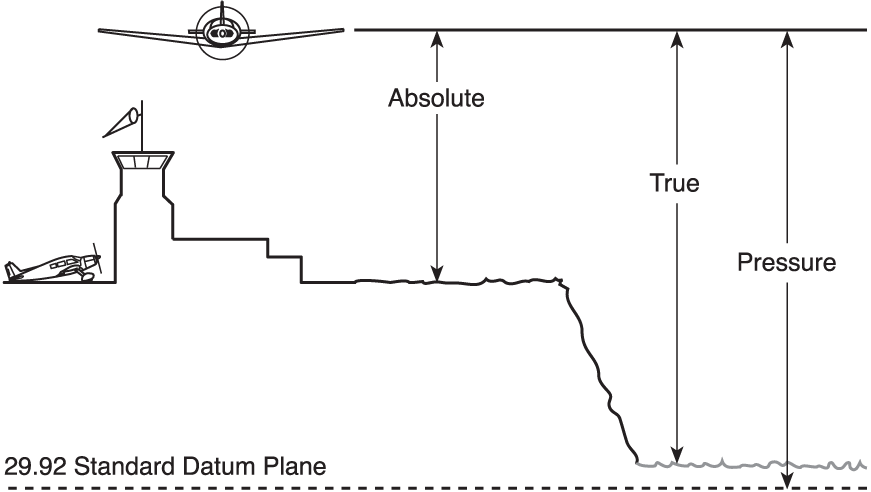
Absolute Altitude
The vertical distance of an aircraft above the terrain, or above ground level (AGL).
Density Altitude
Pressure altitude corrected for variations from standard temperature. When conditions are standard, pressure altitude and density altitude are the same. As the density of the air increases (lower density altitude), aircraft performance increases. Conversely, as air density decreases (higher density altitude), aircraft performance decreases.
In a sense, it's the altitude at which the airplane "feels" it's flying.
-
Formula: Density altitude = Pressure altitude + (OAT-ISA) *120
True Altitude
True altitude is the actual elevation above mean sea level.
Altimeter Check
- When the altimeter setting is set to 29.92'' Hg, it reads pressure altitude.
- When the local altimeter setting is set, there is no more than 75 feet difference with the field elevation
Altimeter Error
-
Mechanical error:
-
A preflight check to determine the condition of an altimeter of setting the barometric scale to the local altimeter setting. The error should not be above 75 ft.
-
There are two types of errors
-
Altimeter Setting:
-
It occur when the altimeter is not adjust to local altimeter setting to compensate for nonstandard pressure.
-
High to low look at below
-
Low to high you are in the sky.
-
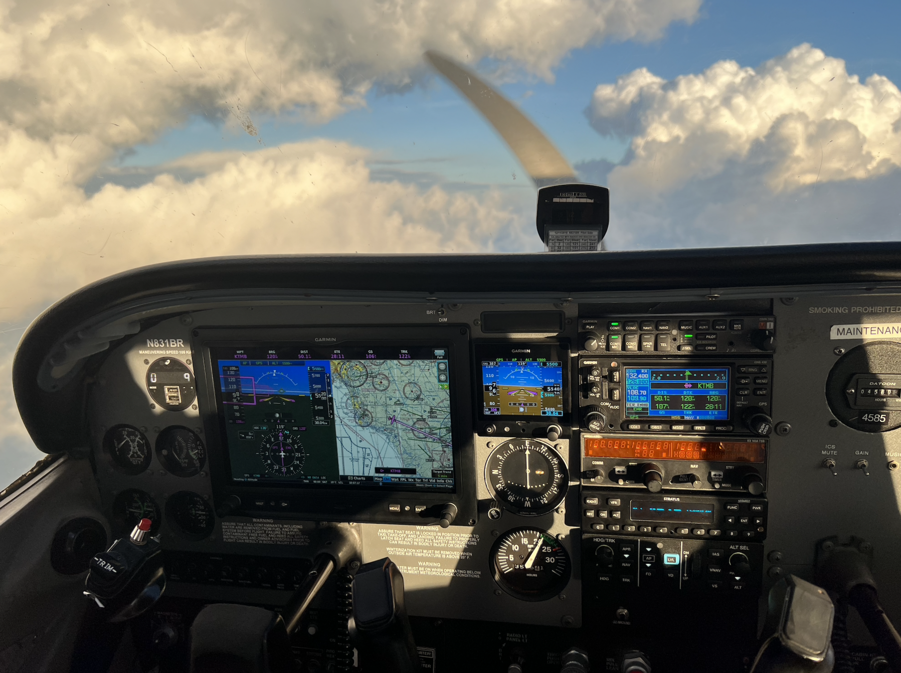
Electronic Flight Displays
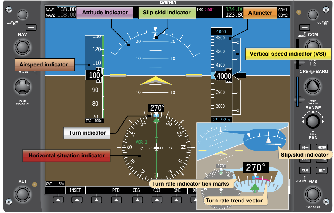
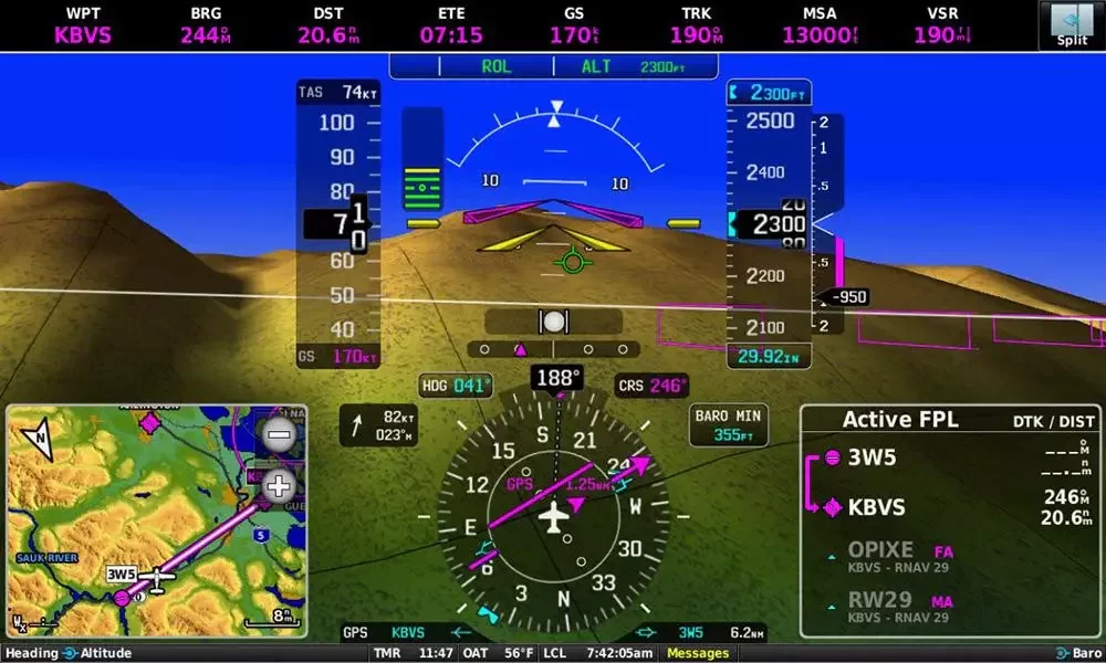
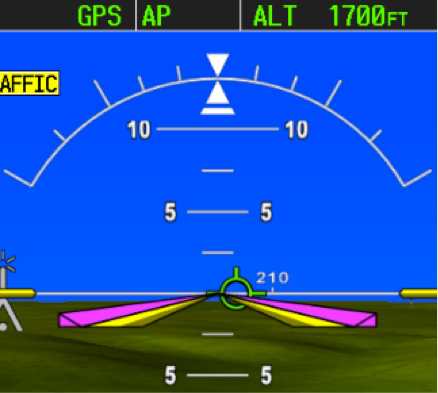
Primary Flight Display (PFD)
Primary Flight Display (PFD) that features a horizon, airspeed, attitude, altitude, vertical speed, heading, and course deviation information.
Airspeed
Altimeter
Vertical Speed Indicator
Attitude Indicator/Turn Coordinator
Heading Indicator
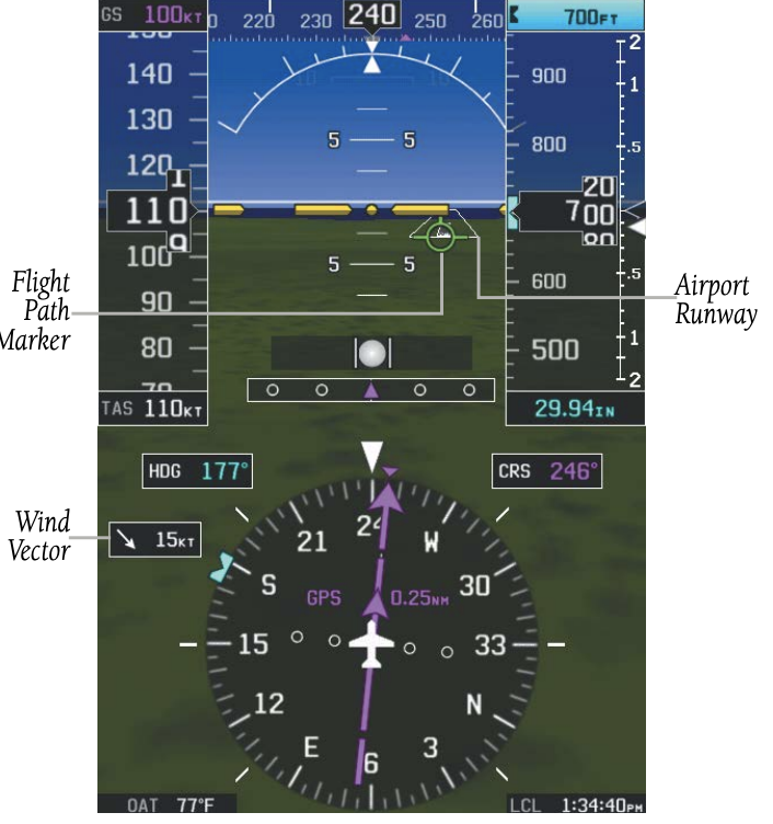
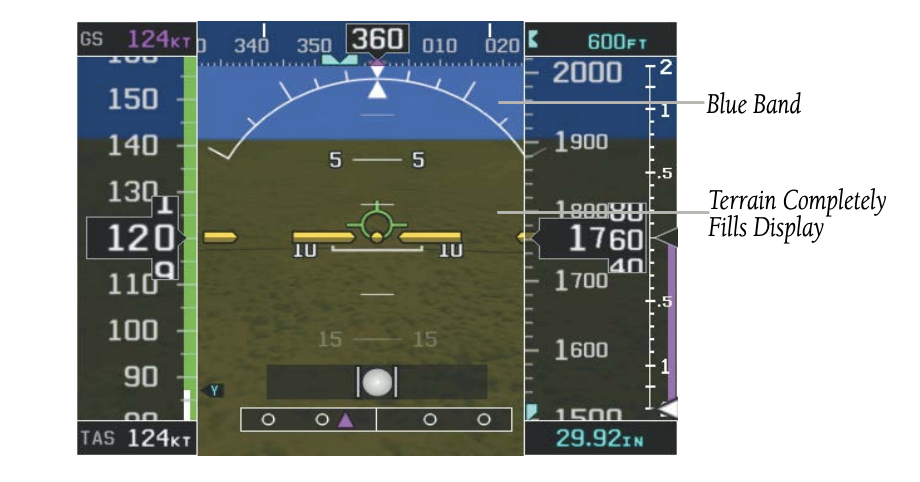
Synthetic Vision
-
Synthetic Vision depicts a forward-looking attitude display of the topography immediately in front of the aircraft, and is shown on the PFD.
- The depicted imagery is derived from the aircraft attitude, heading, GPS three-dimensional position, and databases of terrain, obstacles, and other relevant features.
- Loss of any of the required data, including temporary loss of the GPS signal, will cause Synthetic Vision to be disabled until the required data is restored.
The following Synthetic Vision enhancements appear on the PFD:
Pathways
Flight Path Marker
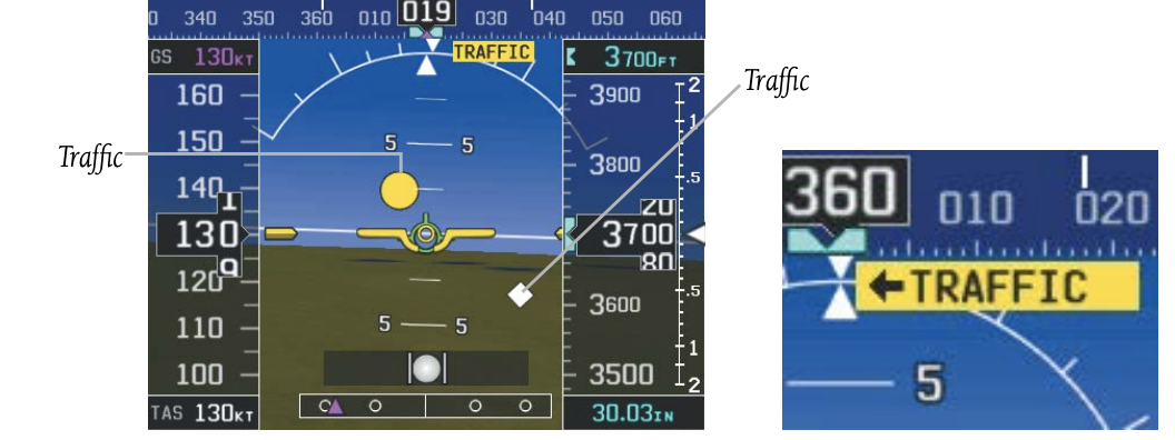
Traffic Display
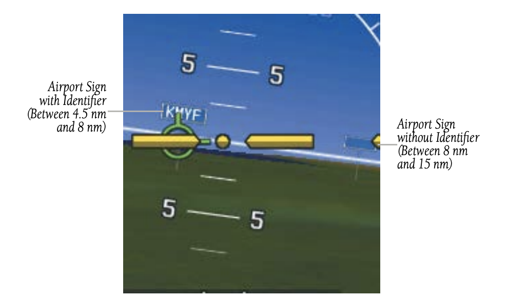
Airport Signs
Zero-Pitch Line
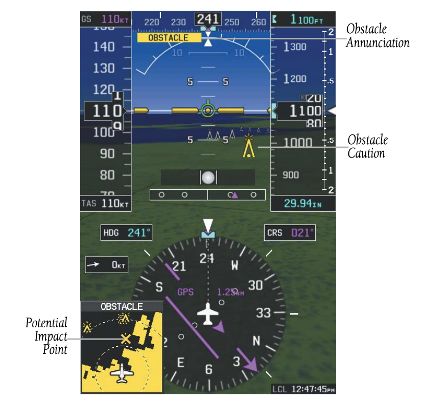
Obstacle Alerting
Terrain Alerting
Runway Display
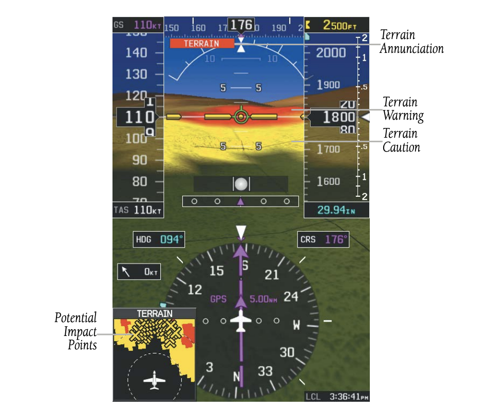
No Reference
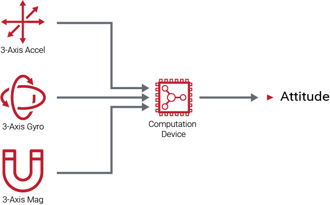
Attitude and Heading Reference System (AHRS)
- The Attitude and Heading Reference System (AHRS) calculates aircraft attitude and heading using inputs from accelerometers, rate gyros, and magnetometers aligned along three axes.
- Attitude and heading information are updated on the PFD, while the AHRS receives appropriate combinations of information from the external sensor inputs.
How do we get information on the PFD
- The AHRS uses a set of sensors contained within an Inertial Measurement Unit (IMU). The IMU measures changes in the aircraft’s attitude and motion using accelerometers and rate gyros, and sends this unprocessed (“raw”) data to the system processor. The processor applies a Kalman filter to integrate and refine the data, then computes accurate attitude and heading information and sends it to the Primary Flight Display (PFD).
- Heading information is derived primarily from a magnetometer, which senses the Earth’s magnetic field lines and provides directional reference to the AHRS.
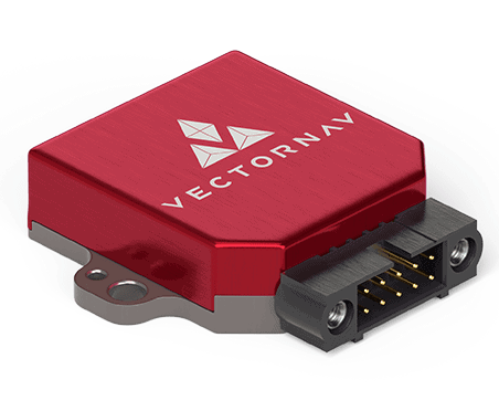
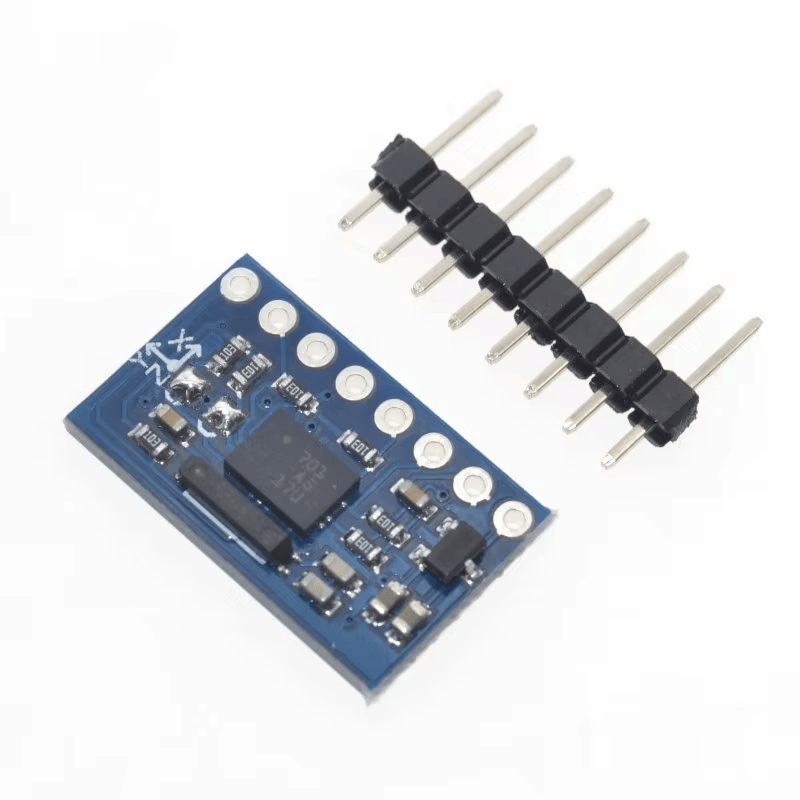
IMU
- The IMU uses Micro-Electromechanical Systems (MEMS) sensors. MEMS technology provides compact, reliable, and cost-effective sensors that measure aircraft motion in multiple axes.
-
The MEMS-based IMU typically includes:
- Accelerometers on three axes, which sense linear acceleration and gravity and help determine pitch and bank
- Gyroscopes on three axes (roll, pitch, and yaw), which measure rotational rates
- Magnetometers on three axes, which sense the Earth’s magnetic field and provide heading reference
- The IMU sends this unprocessed (“raw”) sensor data to the AHRS processor, where a Kalman filter blends and corrects the information. The processor then computes accurate estimates of aircraft pitch, bank, and heading, which are displayed on the Primary Flight Display (PFD).
- Accelerometer:
- It detects the direction of gravity and uses it as a reference to establish the position of the horizon. It is vital for the initial alignment of the system.
- Gyroscopes:
- It is not a real gyro.
- Magnetometer:
- The biggest problem with the magnetometer is that it is affected by electromagnetic interference from the avionics and/or engine. To avoid this, the AHRS can receive information from a remote flux valve.
- Upon power-up, the AHRS unit must first align itself and determine the initial attitude of the aircraft. For this, the aircraft must be stationary and on a level surface for greater accuracy.
Initial Alignment
- In case of a unit failure in the air, the restart must be done when the aircraft is in straight and level, unaccelerated flight for maximum accuracy.
Attitude Indicator
- The attitude indicator receives its information from the AHRS.
- Information is displayed over a virtual blue sky and brown ground with a white horizon line, that spans the entire width of the PFD.
- The horizon line is part of the pitch scale. Pitch markings occur at 2.5˚ intervals through all pitch ranges.
The Attitude Indicator displays
-
Pitch
-
Slip/Skid
-
Roll
- Angle of bank is indicated by the position of the pointer on the roll scale.
- Slip/skid information is indicated by the location of the ball.
- Pitch indicated by the yellow symbolic aircraft on the pitch scale
Horizontal Situation Indicator (HSI)
- The current track is represented on the HSI by a magenta triangle and dashed line. The HSI also presents course deviation, bearing, and navigation source information.
- The objective of this instrument is to eliminate errors in the Magnetic Compass, Heading Indicator, and VOR, such as reverse sensing.
- The HSI combines a VOR, a heading indicator, and a magnetic compass in one single instrument.
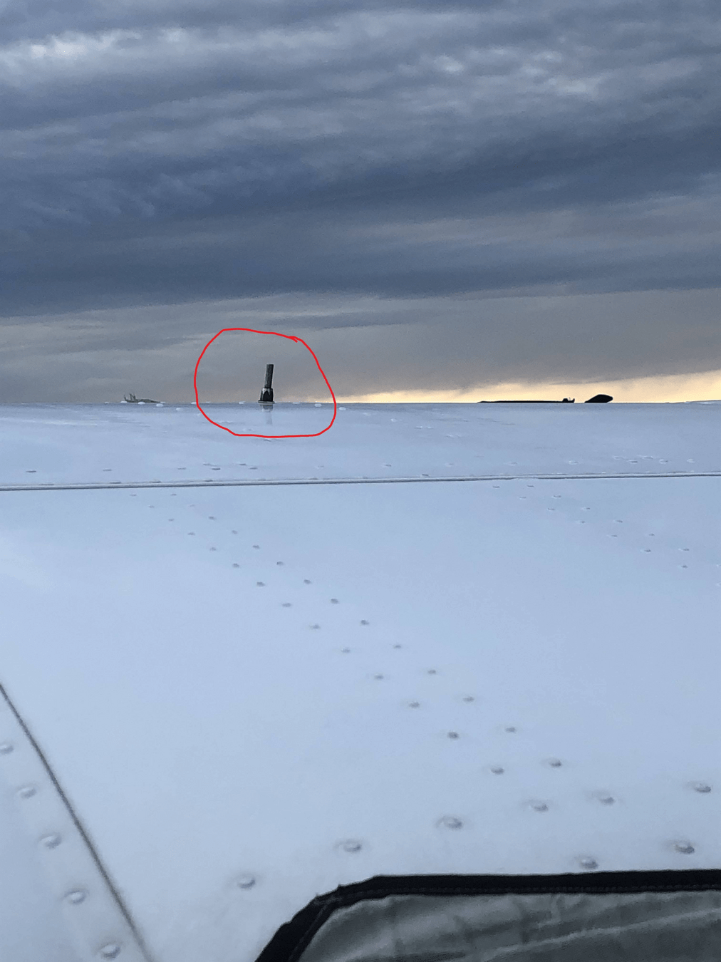
- For this, the HSI uses a Remote Indicating Compass (RIC) located either on the wingtip or inside the empennage to eliminate deviation errors.
- The heading indicator receives information from the magnetometer, which feeds data to the AHRS unit and then to the PFD. However, since the magnetometer is located inside the cabin, it is also affected by electromagnetic fields produced by the instruments and equipment, which affects the accuracy of the heading indicator.
Remote Indicating Compass (RIC)
- Incorporates a magnetic correction system that automatically realigns the gyro with magnetic north constantly; thus, the pilot does not have to make any manual correction.
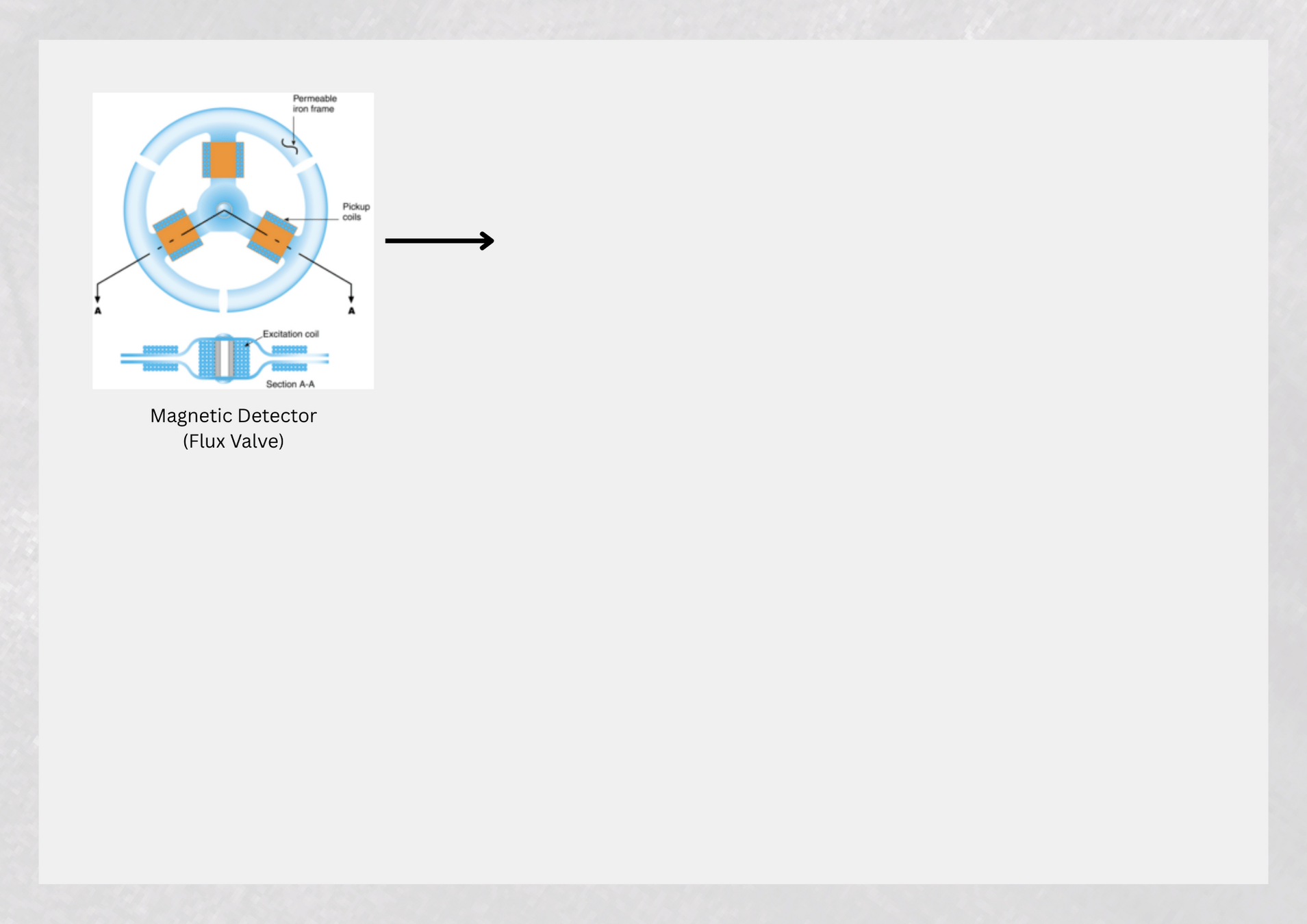
- The Magnetic Detector detects the direction and intensity of the earth's magnetic field flux lines in relation to the orientation of the aircraft.
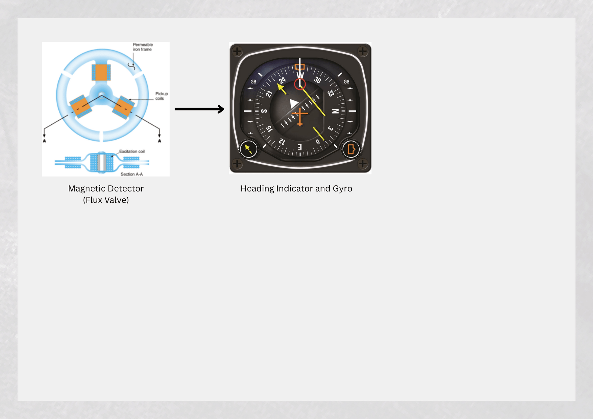
- If they differ, an alternating current (AC) error signal is generated and sent to an amplifier.
- If the detected magnetic heading and the aircraft heading coincide, it means that the instrument is showing the correct heading. Therefore, nothing needs to be corrected.
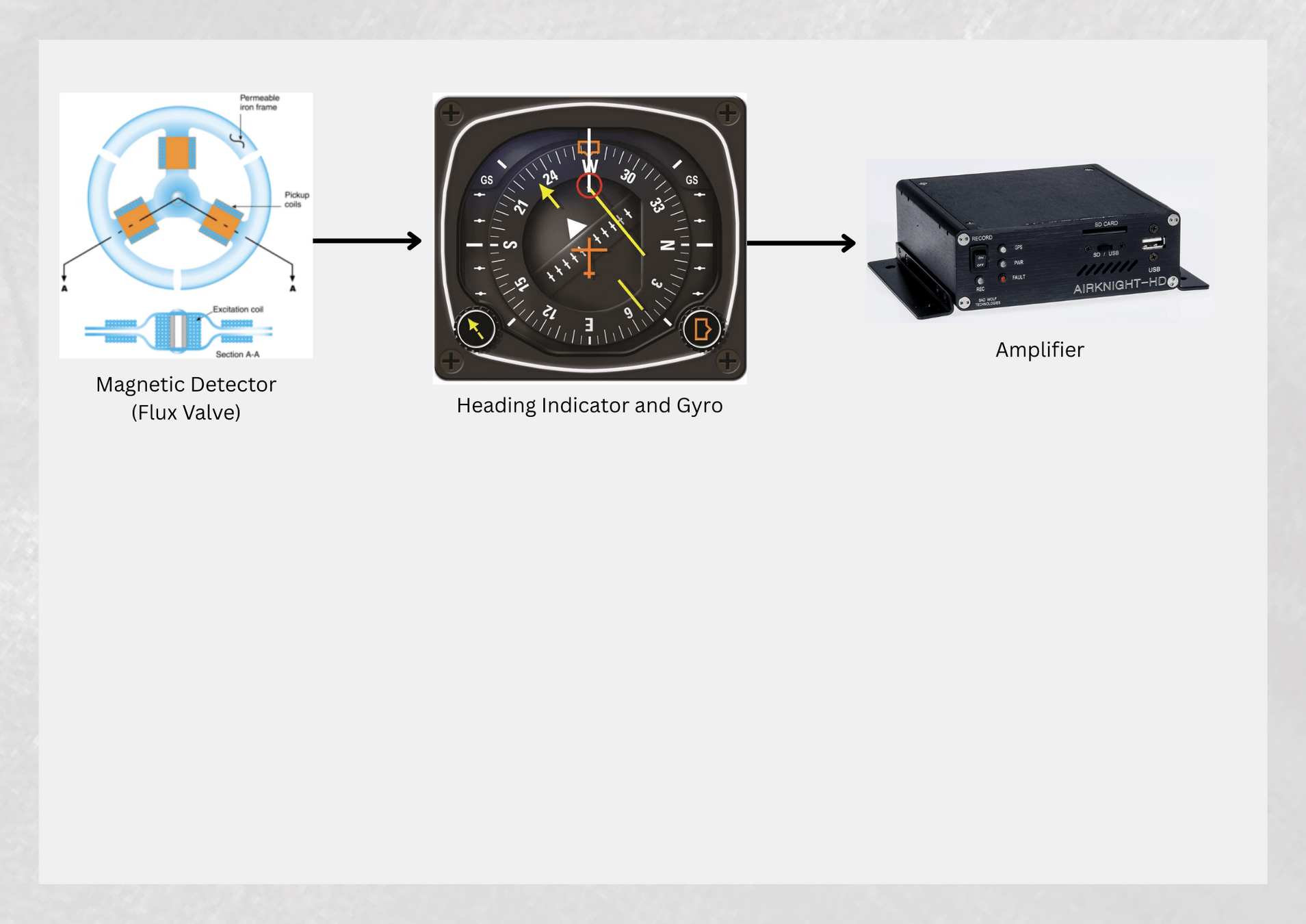
- The amplifier corrects the alternating current error signal into a direct current error signal, and it is amplified enough to activate the precession motor.
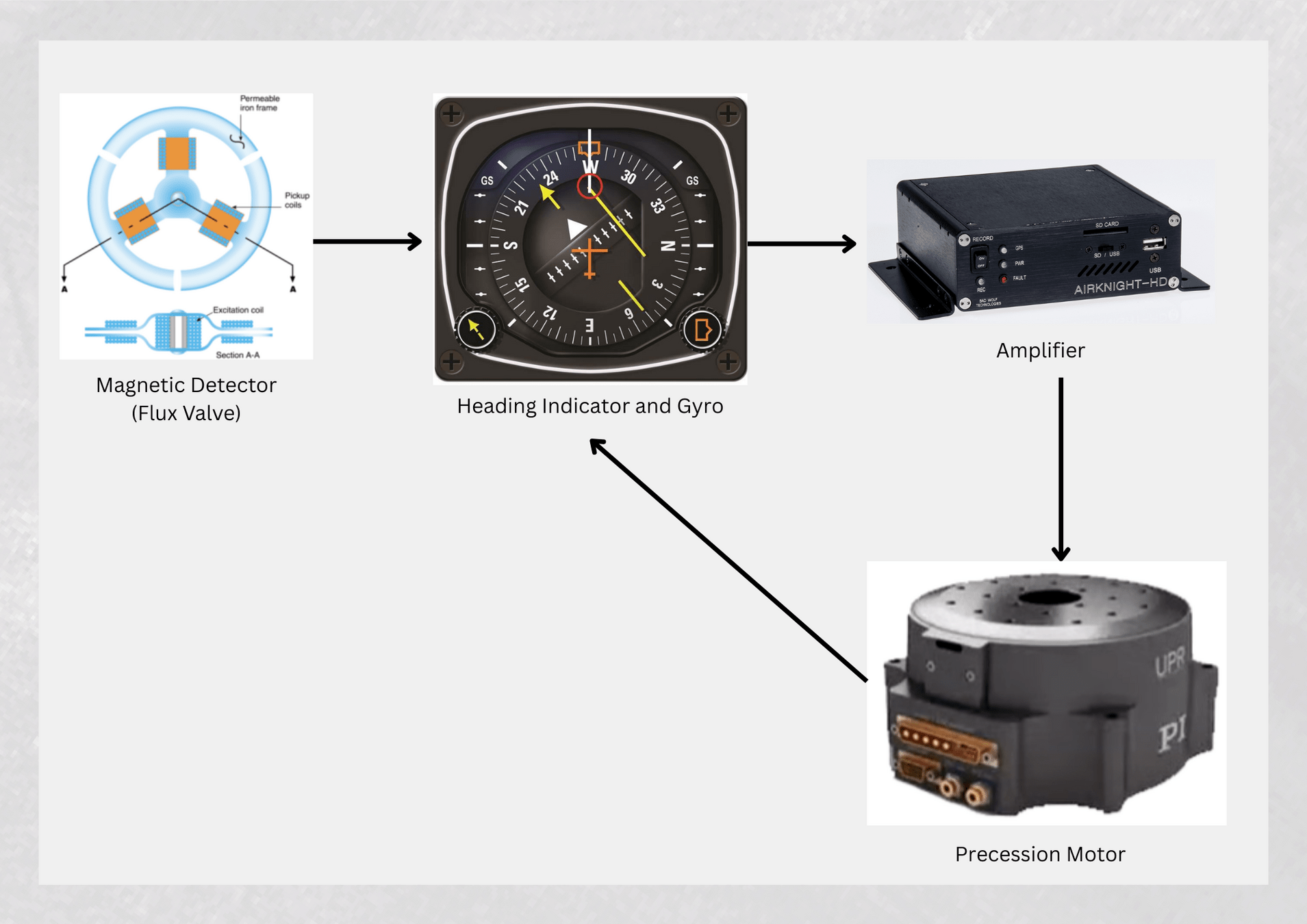
- The precession motor induces a precession in the gyro instrument, which corrects the orientation of the heading indicator to realign it with the magnetic heading.
Lubber line
Current track indicator
Navigation source
Heading bug
Course pointer
CDI
Rotating compass rose
To/From indication
Aircraft symbol
Lateral deviation scale
Course deviation & to/from indicator
Air Data Computer (ADC)
- The pilot receives the airspeed, altitude, and altitude trend data on the FDC through the ADC.
- The pitot static inputs are received by an ADC.
- The ADC computes the difference between the total pressure and the static pressure and generates the information necessary to display the airspeed on the PFD.
But how exactly?

- The Air Data Computer (ADC) receives inputs from the pitot tube, static port, outside air temperature (OAT) probe, and, in some aircraft, an AOA probe.
Temperature probes and AOA probes are devices that are used to measure.
- This "raw" information is converted into an electrical signal thanks to a transducer.
-
Once converted into an electrical signal, it is sent to the ADC Microprocessor, which integrates and processes the data to calculate different parameters, such as:
- Altitude
- Vertical speed
- IAS, TAS
- Outside temperature
- AOA
Airspeed Indicator
- The Airspeed Indicator, on the left side of the PDF, displays airspeed on a rolling number gauge using a moving tape.
- The true airspeed (TAS) is displayed in knots below the Airspeed Indicator.
- The numeric labels and major tick marks on the moving tape are marked at intervals of 10 knots.
- The actual airspeed is displayed inside the black pointer
Altimeter
- The altimeter is located on the right side of the PFD.
- As the altitude increases, the larger numbers descend from the top of the display tape, with the current altitude being displayed in the black box in the center of the display tape.
- The altitude is displayed in increments of 20 feet
Vertical Speed Indicator
(VSI)
- The VSI is displayed to the right of the altimeter tape.
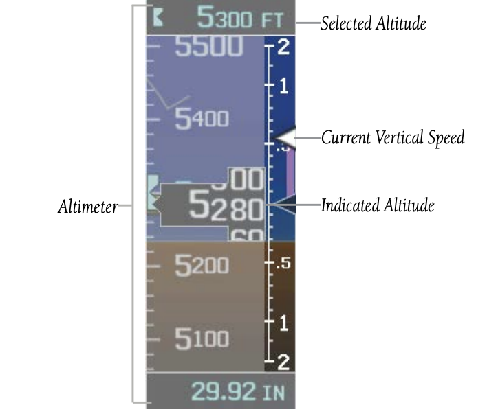
- The Vertical Speed Indicator displays the aircraft's vertical speed using a non-moving tape labeled at 500, 1,000, and 2,000 fpm, with minor tick marks every 100 feet up to 1,000 fpm.
The current vertical speed is displayed using a white arrow along the tape.
PFD Failures
- A PFD failure is not consist an emergency because the PFD screen will trigger a reversion mode that takes over the MFD
How to recognize PFD Failures
- Loss of GPS Position
- AHRS/ADC Failure
- Reverse Mode
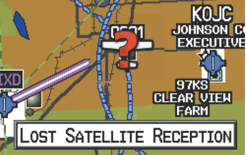
Loss of GPS Position
- A blinking red question mark will appear over the airplane icon on the map.
- The ‘Lost Satellite Reception’ message will display.
- Any GPS dependent data fields will not be available
click here
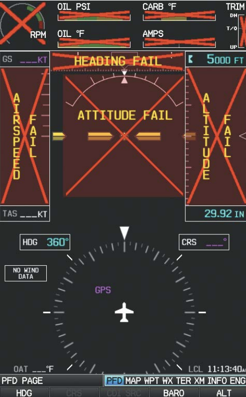
AHRS/ADC Failure
click here
- An AHRS failure is indicated by red “X”s over the affected flight instruments and a loss of the horizon line on the PFD
- The AHRS provides attitude information while the ADC gives data like airspeed, altitude and vertical speed.
- When the AHRS and/or ADC fail, the pilot should refer to standby instruments.
click here
- An AHRS failure also causes power loss to the Magnetometer, thus the magnetic heading indications are no longer displayed on the HSI and a red “X” appears over the current heading indication.
- Use the DTK and TRK numbers from the GPS for direction.
- The ADC depends on traditional pitot/static input.
Reverse Mode
- In a two display system, in the event of a PFD failure, the MFD goes into reversionary mode, and the autopilot is disengaged.
- If the MFD fails, the PFD goes into reversionary mode and the autopilot continues to function
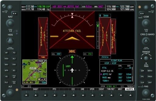
Failure Of The External Gps Navigation Source
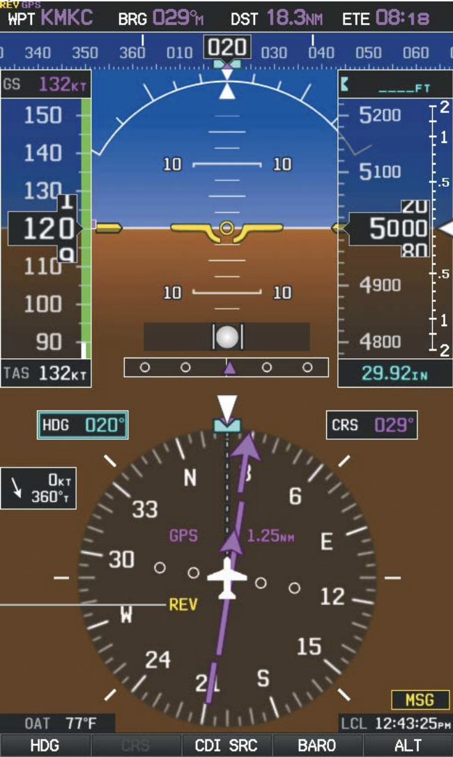
External GPS Failure
Reverted to Internal GPS
click here
External Navigation Source failed
Reverted to internal VFR GPS for navigation
If the external GPS navigation source fails, the system reverts to the internal GPS navigation source and ‘REV’ is shown in yellow in the upper left corner of the Data Bar as well as the lower left quadrant of the HSI.
If the external GPS navigation source fails, the system reverts to the internal GPS navigation source and ‘REV’ is shown in yellow in the upper left corner of the Data Bar as well as the lower left quadrant of the HSI.
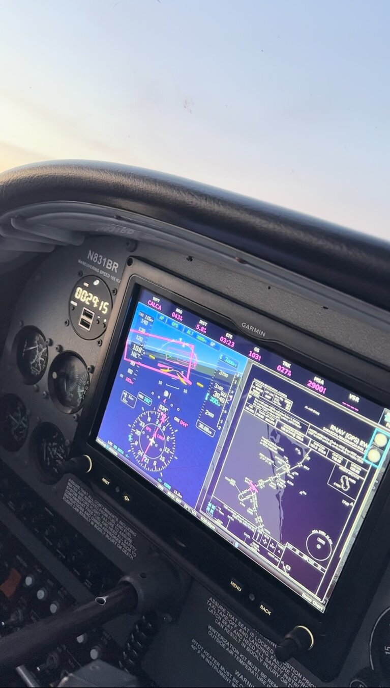
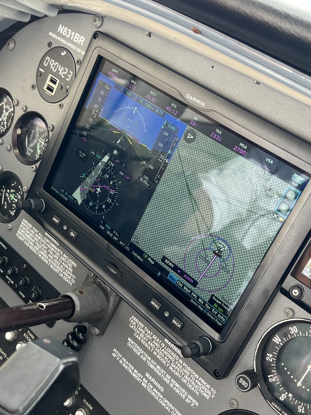
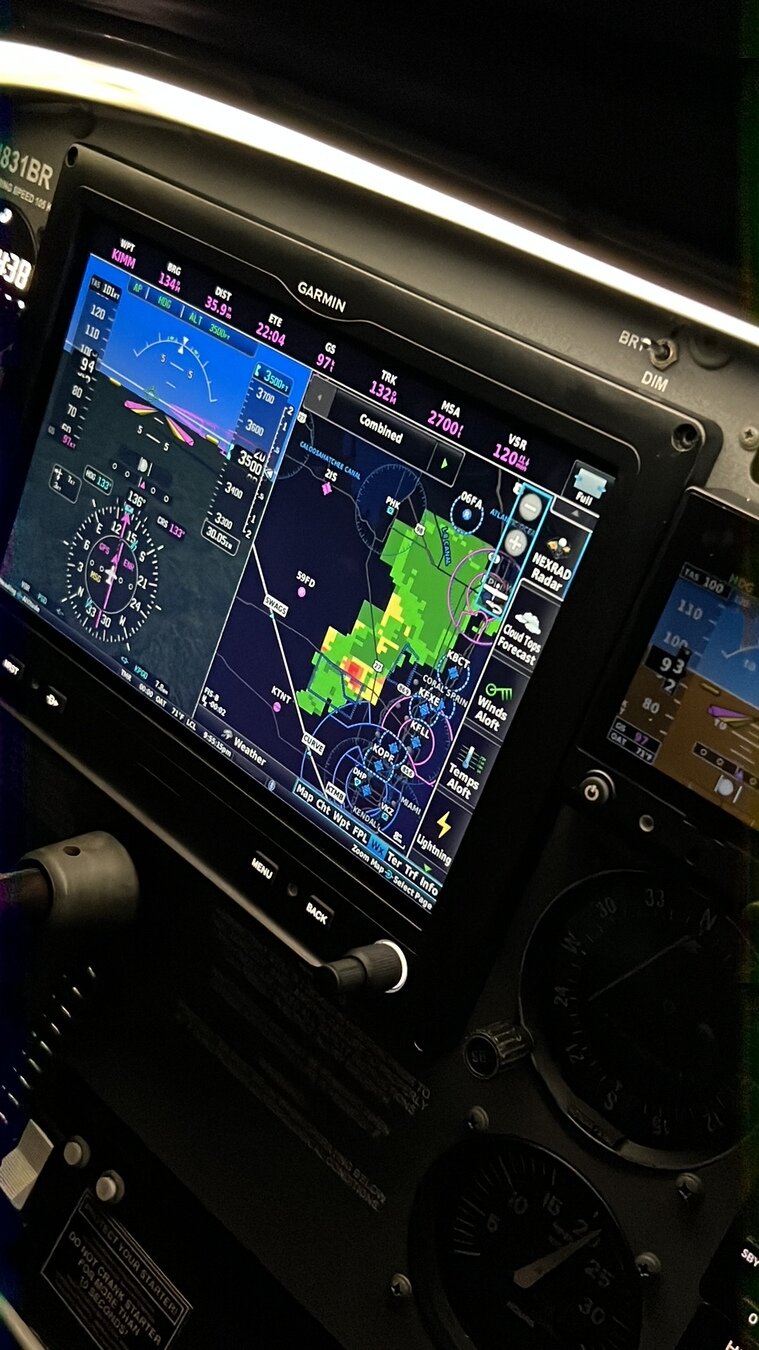
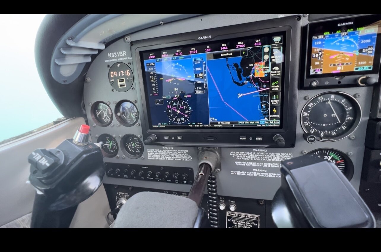
Multifunction Display (MFD)
Features
- The MFD is used primarily for navigation display, and together with a primary flight display (PFD
- Many MFDs allow pilots to display their navigation route, moving map, weather radar, NEXRAD, ground proximity warning system, traffic collision avoidance system, and airport information on the same screen.
- If the PFD fails, its information will automatically appear on the MFD, and the autopilot can still be used.
Map Display
-
A moving map using Global Positioning System (GPS) navigation with the aircraft position displayed.
- MFD and display maps provide a high level of situational awareness; pilots can Improve safety by flying more informed and aware.
Automation
Operation
- Automation is playing a key role in the aviation industry by controlling the flight management systems of the aircraft.
- It works by sending signals to the flight control system. The pilot inputs what type of mode they want, like a heading or an altitude hold mode.
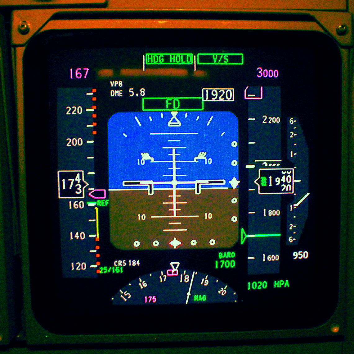
Flight Director
-
The flight director (FD) is an element of a plane's automatic flight control system.
- The flight director function provides pitch and roll commands to the pilot and autopilot, which are displayed on the PFD. With the flight director active, the aircraft can be hand-flown to follow the path shown by the Command Bars.
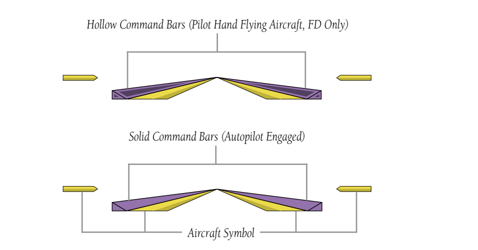
Command Bars
-
Most traditional flight director display is the command bar layout (sometimes called the "v-bar").
- Command bars are a set of two triangular lines that match the shape of the airplane symbol on the primary flight display or attitude indicator.
Purpose of Command Bars
-
The command bars move up, down, left, and right as a guide for the flying pilot to match and fly the path that has been selected in the flight management system.
- When the autopilot is engaged, the pitch and roll servos follow the flight director's commands during all turns, level-offs, and descents.
-
Upon activation of the flight director, Command Bars are displayed in magenta on the PFD.
- If the attitude information being sent to the flight director becomes invalid or unavailable, the Command Bars are removed from the display