GL 4 Instrument Navigation (VOR, GPS)

Rev 01/2025
Disclaimer
Students should use their textbooks, syllabus, and Airman Certification Standards (ACS) as their primary sources of information. EcFlight is an online training tool designed to simplify and enhance your ground school learning experience. However, it is not a substitute for FAA- or school-approved study materials. Before using these slides for study, always refer to your officially approved resources, such as the Jeppesen physical or electronic book and other FAA-approved materials.
Reference Books
- Pilot's Handbook of Aeronautical Knowledge(FAA-H-8083-25B). (2016). Oklahoma City, OK: United States Department of Transportation, Federal Aviation Administration, Airman Testing Standards Branch.
- Instrument Flying Handbook faa-h-8083-15B. (2012). Oklahoma City, OK: United States Department of Transportation, Federal Aviation Administration, Airman Testing Standards Branch.
- Instrument Pilot Syllabus (10001785-003). (2015). Englewood, CO: Jeppesen
- Cessna. (1976). Pilot's Operating Handbook(D1057-13). Wichita, KA: Cessna.
Reference Multimedia
- ERAUSpecialVFR. (n.d.). Motion picture.
- https://www.experimentalaircraft.info/articles/aircraft-vacuum-gyro-system.php
- https://www.youtube.com/watch?v=iCCk2ch-xL4
- https://www.grc.nasa.gov/www/k-12/airplane/move.html
-
https://www.youtube.com/watch?v=608S92wSTbg&t=1s&index=15&list=PLwjRk1KeIz4iwz8uMCwt5U1-2BQlKmZs5
-
https://www.youtube.com/watch?v=IoRQiNFzT0k
Index

VOR Navigation
- VOR is the primary navigational aid (NAVAID) used by civil aviation in the National Airspace System (NAS).
- There are different types of VOR navigation, including basic VOR, horizontal situation indicator (HSI), and radio magnetic indicator (RMI).
- VOR frequencies range from 108.0 to 117.95 MHz.
Ground and Airborne Equipment
VOR provides magnetic bearing information TO and FROM the station.
(Very High Frequency Omni Directional Range)
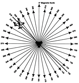
Ground Station Projects straight-line courses (radials) from the station in all directions. Two signals provide complete information to the aircraft: Reference Signal and Rotating Signal.
Aircraft equipment senses the time between the rotating signal and the reference signal, and deflects the needle set on the NAV display or CDI selector.
1) VOR ground stations transmit within a VHF frequency band of 108.0–117.95 MHz.
2) The prefix “Omni-” means all, and omnidirectional projects straight line courses (radials) from the station in all directions.
- Radials are identified by numbers beginning with 001.
3) Range Limited. Divided into different service volumes of VOR.
(Very High Frequency-Omni Directional-Range)
Service Volumes: VOR is limited by ranges depending on the type of VOR in use, starting from 1,000 ft.
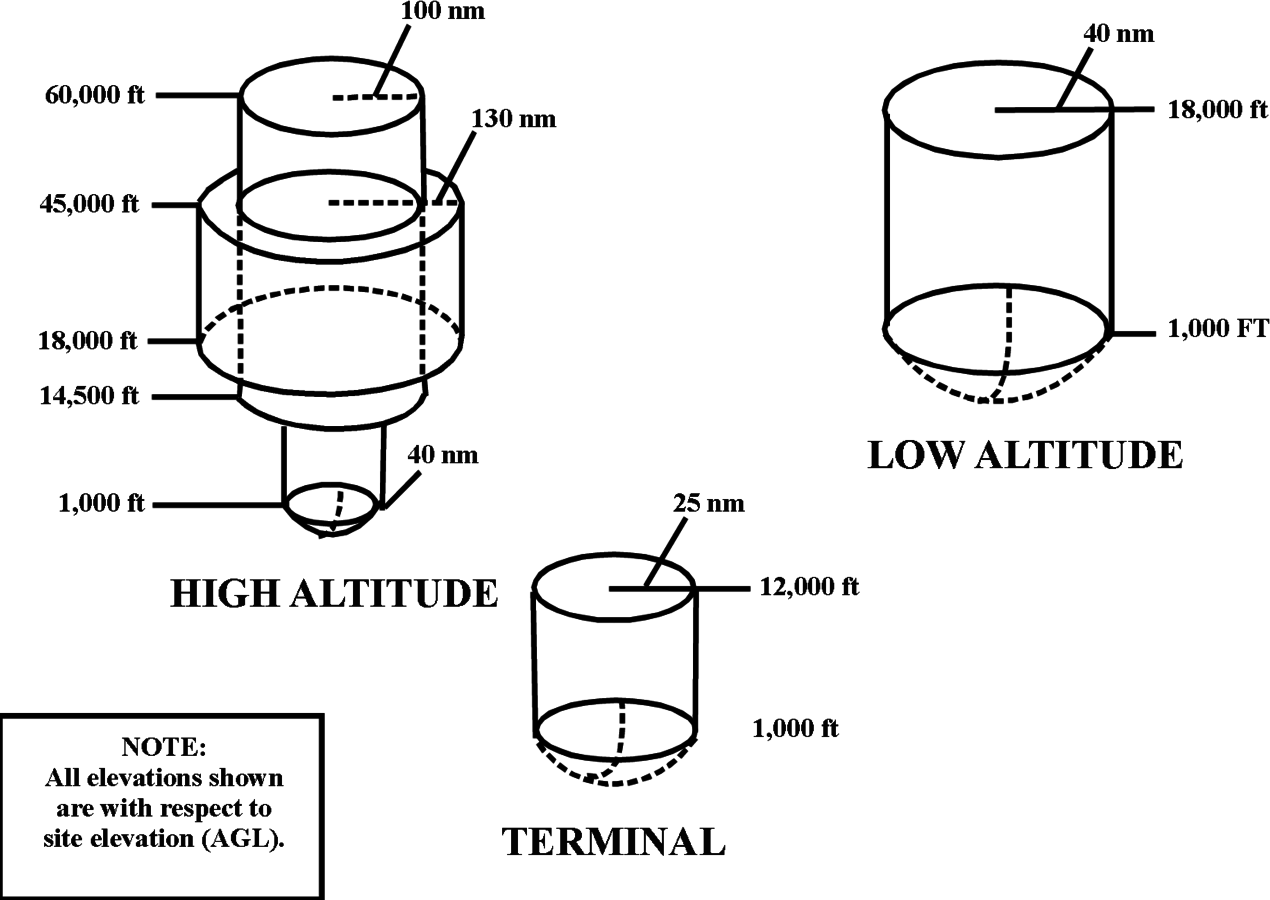
Legacy Service Volumes
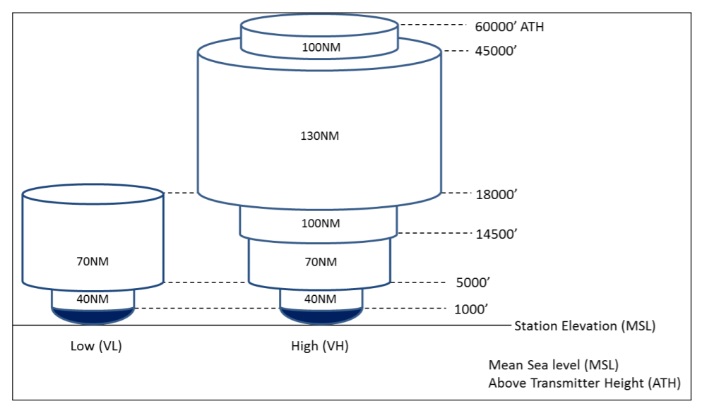
New Service Volumes
Present in three different Navigation aids (NAVAIDs)
- VOR: Does not provide distance from station
- VOR/DME: DME is also installed with a VOR. will provide Distance from station.
- VORTAC: When military tactical air navigation equipment is installed with a VOR (TACAN). DME is always an integral part of a VORTAC.
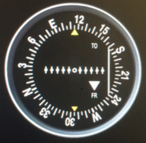
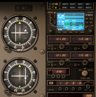
Horizontal Situation Indicator
The HSI combines a heading indicator and VOR indicator in a single display. This reduces pilot workload by lessening the number of elements in the pilot's instrument scan to the six basic flight instruments.
Interpreting a Course
Turn the omnibearing selector (OBS) knob until the course deviation indicator (CDI) needle centers with a FROM indication and read the resulting radial next to the index mark on the top of the VOR indicator.
VOR Navigation
Tracking
When tracking, you maintain the selected course by keeping the CDI centered.
Determining Your Progress
Use two VORs to check your progress along the route. Tuning your second VOR receiver to the station located to the side of your route will provide precisely the progress of the flight.
Time and Distance to the Station
You can use formulas to determine the time and distance from a station.
Station Passage
When you are close to the station, the CDI will become very sensitive and TO/FROM indications will fluctuate. Station passage will be indicated by the complete reversal of the TO/FROM indicator.
VOR Operational Considerations
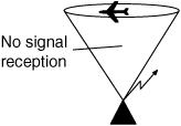
Cone of confusion: A cone-shaped volume of airspace directly above a VOR station where no signal is received, causing the CDI to fluctuate.
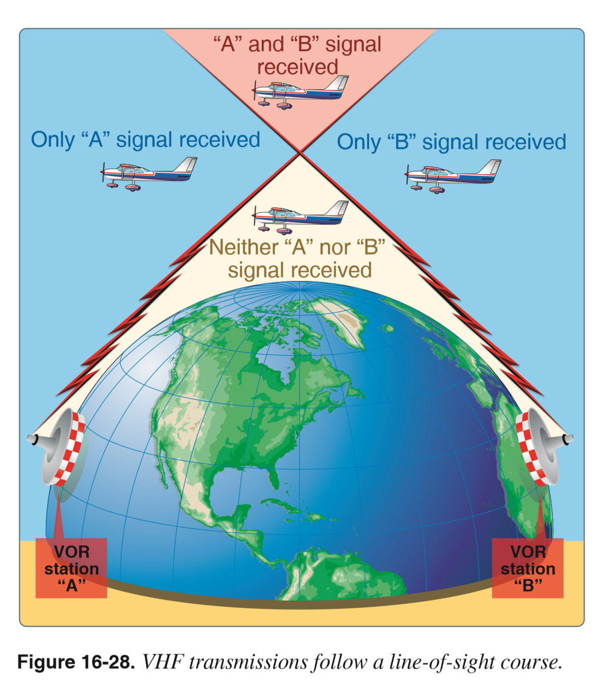
Demonstration
The line of Sight: VOR uses VHF signals they are susceptible to Obstacles and aircraft might not be able to receive signal.
Service Volumes: VOR is limited by ranges depending on the Type of VOR in use starting from 1,000ft.
New Service Volumes
Legacy Service Volumes
But what about below 1,000 feet?
High And Low VOR
Terminal VOR
You can still receive signal depending on the aircraft's altitude.
Airborne Equipment Error: Caused By magnetic interference inside the aircraft like the GPS or Radios.
Zone of Ambiguity
Reverse Sensing
VOR Checks
Checking VOR Accuracy
The accuracy of course alignment of VOR radials is considered to be excellent. However, certain parts of the VOR receiver equipment deteriorate, and this affects its accuracy.
VOR accuracy checks are not a regulatory requirement for VFR flight. The VOR Check must be done every 30 days.
Checking VOR Accuracy (30Days)
Vot - +/- 4 specific station on the ground, check AF/D.
Bench - only by a mechanic.
Ground - +/- 4 specific places in the airport, check AF/D.
Airborne - +/- 6 using specific checkpoints, check AF/D.
Inflight - +/- 6 using Victor airways
Dual - not exceed 4 between 2 VOR receivers.
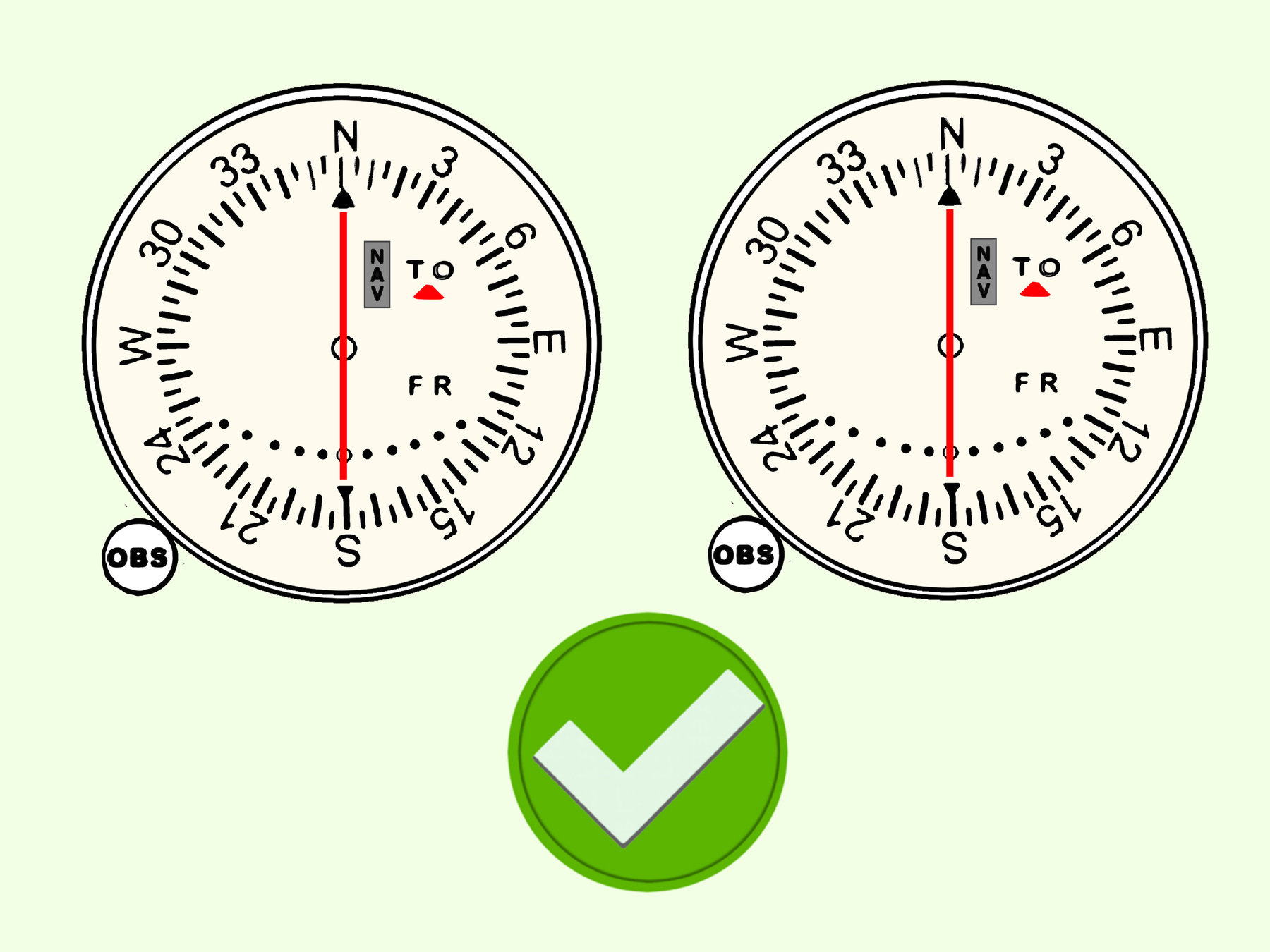
VOT (Test Facilities)
- Can Be used in most locations of an airport.
- VOT facilities transmit only one radial. Tune and identify the frequency and set the course selector to 180° with a TO indication or 360° with a FROM indication. The needle should center, +/- 4°.
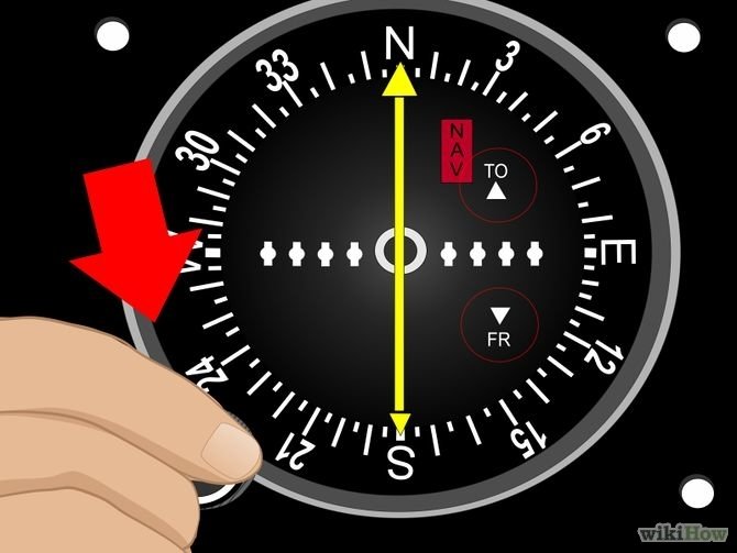
FROM
TO
Bench (Mechanics)
Bench checks are performed by an authorized Mechanic (A&P).

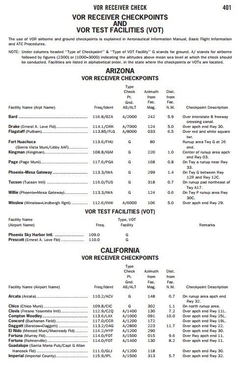
Ground and Airborne Checks
- Ground and airborne checks should be received at specific points on the airport surface or over specific landmarks while airborne in the immediate vicinity of the airport.
- Locations of these checkpoints are published in the A/FD. Error Tolerance +/- 4°.
Inflight Checks
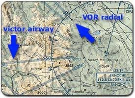
- Select a VOR radial that defines the centerline of an airway. Then, locate the prominent terrain feature with the sectional chart (Preferably more than 20NM from the station).
- Error Tolerance is +/- 6°.
Dual Checks
- If a dual system VOR is installed in the aircraft, one system may be checked against the other.
- Turn both systems to the same VOR ground facility and note the indicated bearing to that station. The maximum permissible variation between the two indicated bearings is 4°.
Distance Measured Equipment (DME)
- Enables you to keep track of your distance to or from a VOR, TACAN or VORTAC.
- DME gives you SLANT RANGE DISTANCE to the station.
- Can be received up to 199 NM from the station.
DME is required above FL240
- Aircraft send pulses to the station, then the station transmits pulses back, the time this process takes is measured in the DME unit and is translated into a distance in NM.
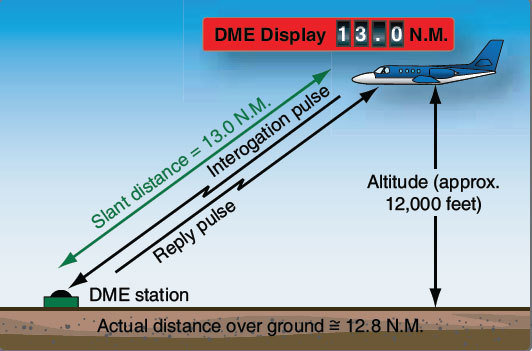
DME Considerations
- An error is caused by the DME since the signal travels in a straight line to and from the ground station.
- DME is accurate when you are at least one horizontal mile from the station for every 1.000 feet above the field elevation.
DME Arcs
There are many instrument approach procedures (IAPs) that incorporate DME arcs.
Maintaining the arc is simplified by keeping the aircraft slightly inside the curve; thus, the arc is turning toward the aircraft and interception may be accomplished by holding a straight course.
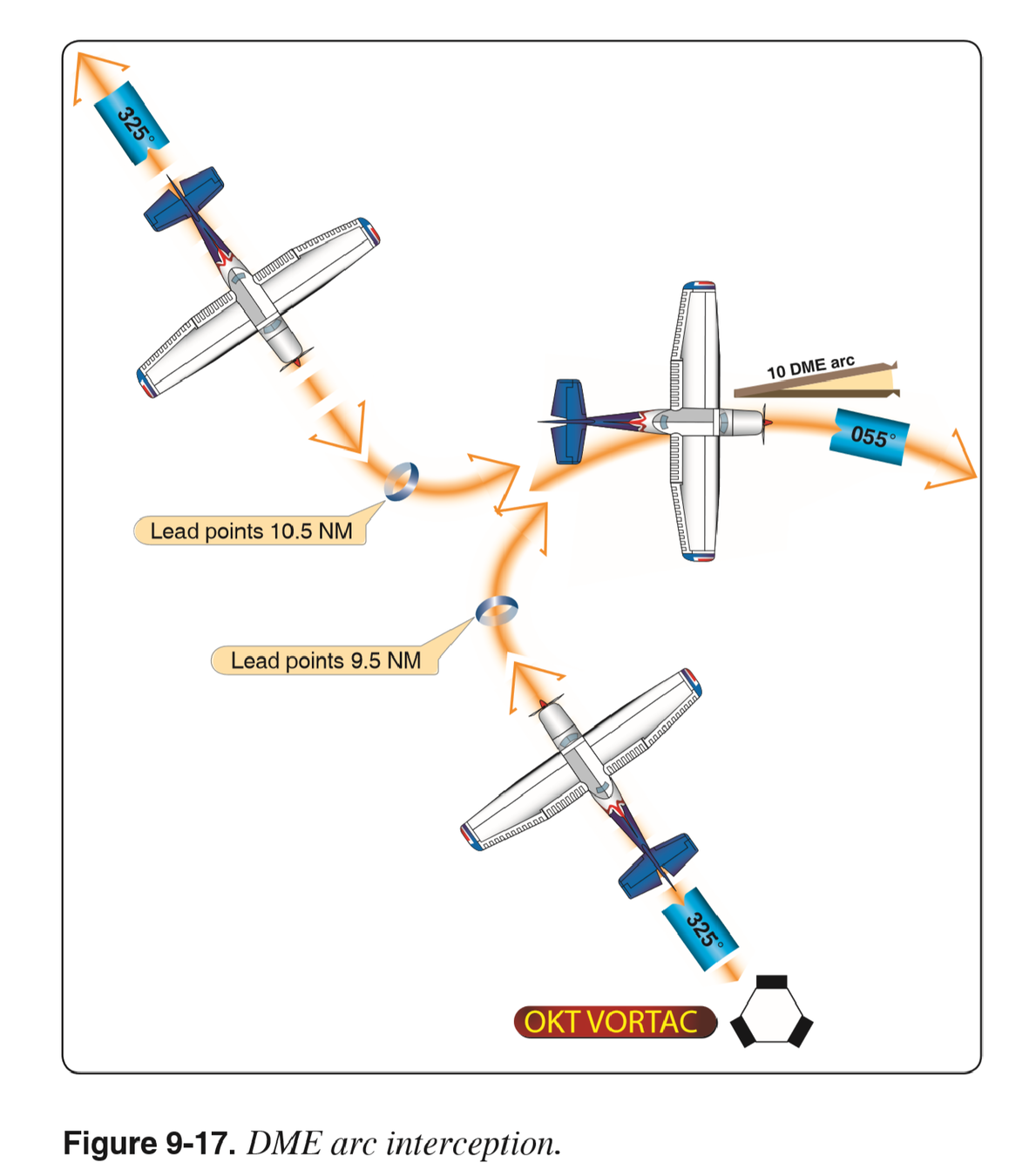
Flying a DME Arc
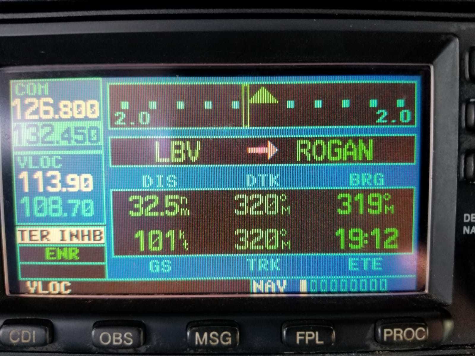
Area Navigation
- Area Navigation (RNAV) is any equipment that computes the aircraft's position, actual track, and groundspeed, and then displays the distance and time estimates to the selected waypoint.
- Waypoints are predetermined geographical positions for a route without using ground facilities.
- Examples are: GPS, VOR/DME, RNAV, Inertial Navigation System (INS).
Required Navigation Performance (RNP)
Required Navigation Performance (RNP)
- Required Navigation Performance (RNP) is a set of standards that apply to both airspace and navigation equipment.
- A critical component of RNP is the ability of the aircraft navigation system to monitor its achieved navigation performance and to identify whether the operational requirement is being met during an operation.
Required Navigation Performance (RNP)
Navigation System, such as GPS must be able to keep the airplane within a specified distance of the centerline of a route, path or procedure for at least 95% of the time.
If the GPS is equipped with WAAS You must operate within:
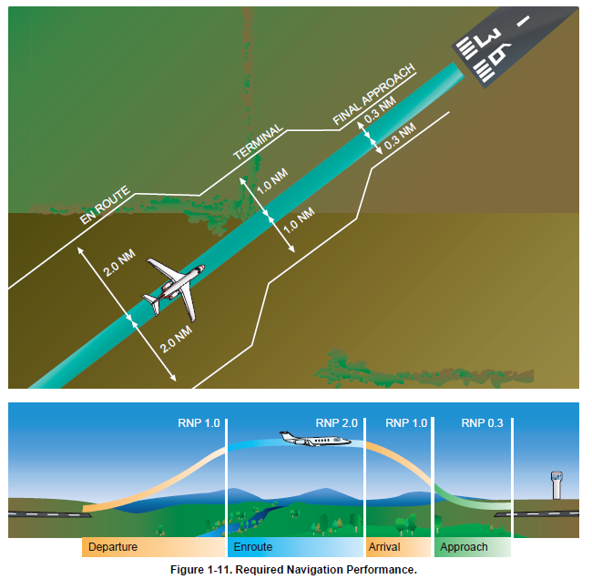
RNP for GPS with WAAS
Enroute
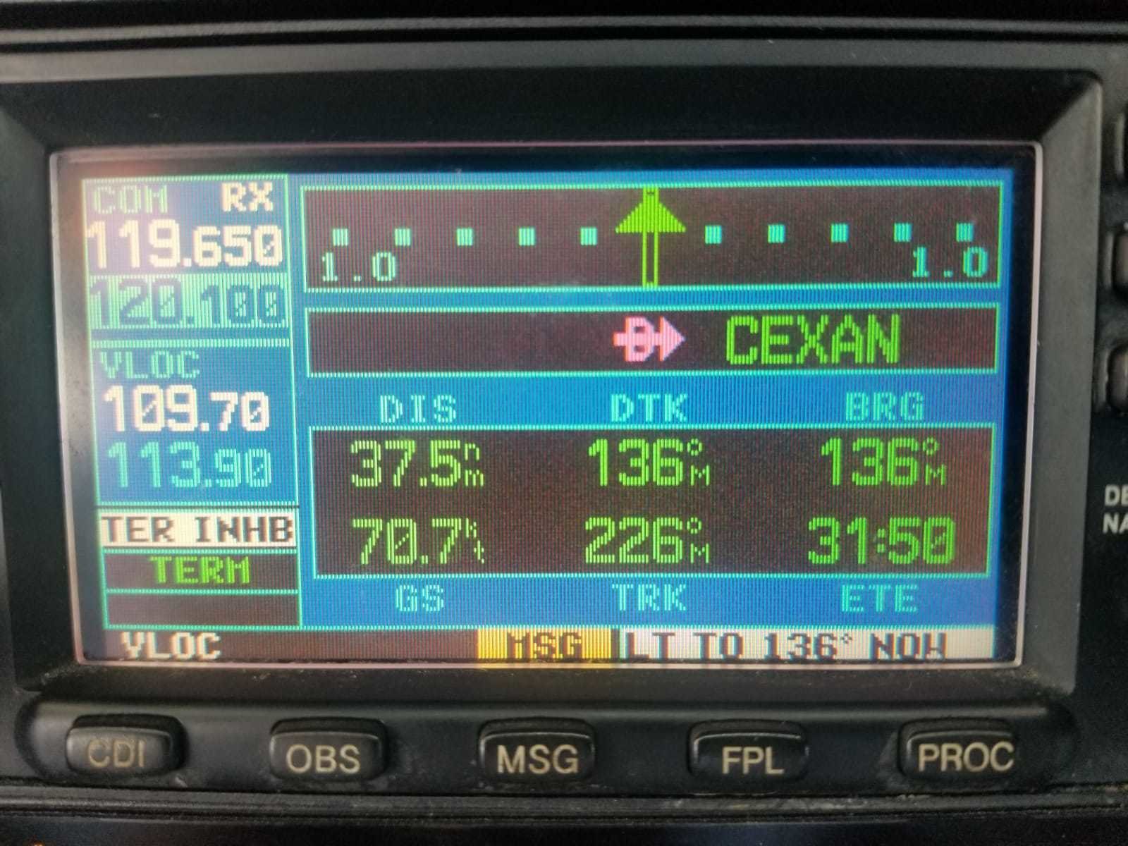
Terminal
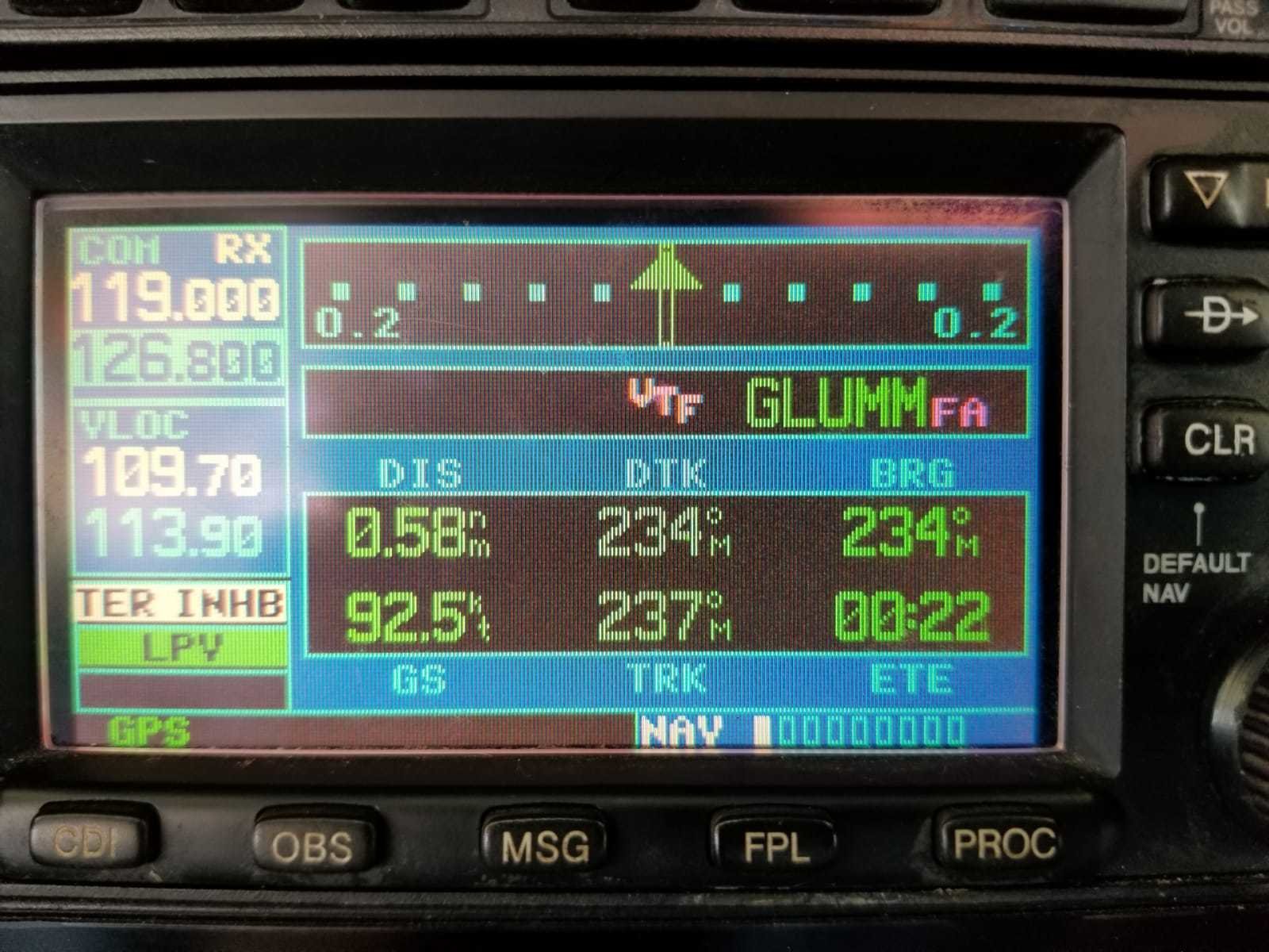
Final App
Inertial Navigation System (INS)

The Inertial Navigation System (INS) is a system that navigates precisely without any input from outside the aircraft. It is fully self-contained. The INS is initialized by the pilot, who enters the exact location of the aircraft on the ground into the system before the flight.
Flight Management System (FMS)
The Flight management system (FMS) manages and automates the task of the onboard navigation equipment. The FMS acts as the input/output device
Satellite Navigation GPS
The GPS is a satellite-based radio navigation system that broadcasts a signal that is used by receivers to determine precise position anywhere in the world.
The constellation of satellites providing a high-frequency signal that contains time and distance and is picked up by a receiver is called the Global Navigation Satellite System (GNSS)
Trilateration
- GPS uses what is called trilateration to determine your location.
- Trilateration is the process of determining a position by knowing your distance from at least three known points. In GPS, those known points are the satellites themselves.
How does GPS work
Composed of three elements:
Space Component
User Component
Control component
Space Component
- Consists of 31 satellites in 6 orbital planes and spaced 55° apart for complete coverage.
- The Satellites broadcasts a pseudo-random code timing signal and data message that the aircraft equipment processes to obtain satellite position. By knowing the satellite position. GPS receivers are able to determine aircraft's exact position.

Space Component
- The aircraft receiver measure the time each satellite signal takes to arrive, therefore, determine aircraft position.
- Each satellite contains four atomic clocks. These clocks are accurate to at least a billionth of a second or a nanosecond.
Ground Component
- Consists of a network of ground-based GPS monitoring and control stations that ensure the accuracy of satellite positions and their clocks.
User Component
- Consists of antennas and receiver on board the aircraft that provide positioning, velocity, and precise timing to the user.
- GPS equipment used while operating under IFR operation must meet the standards in Technical Standard Order (TSO).
Overview of GPS
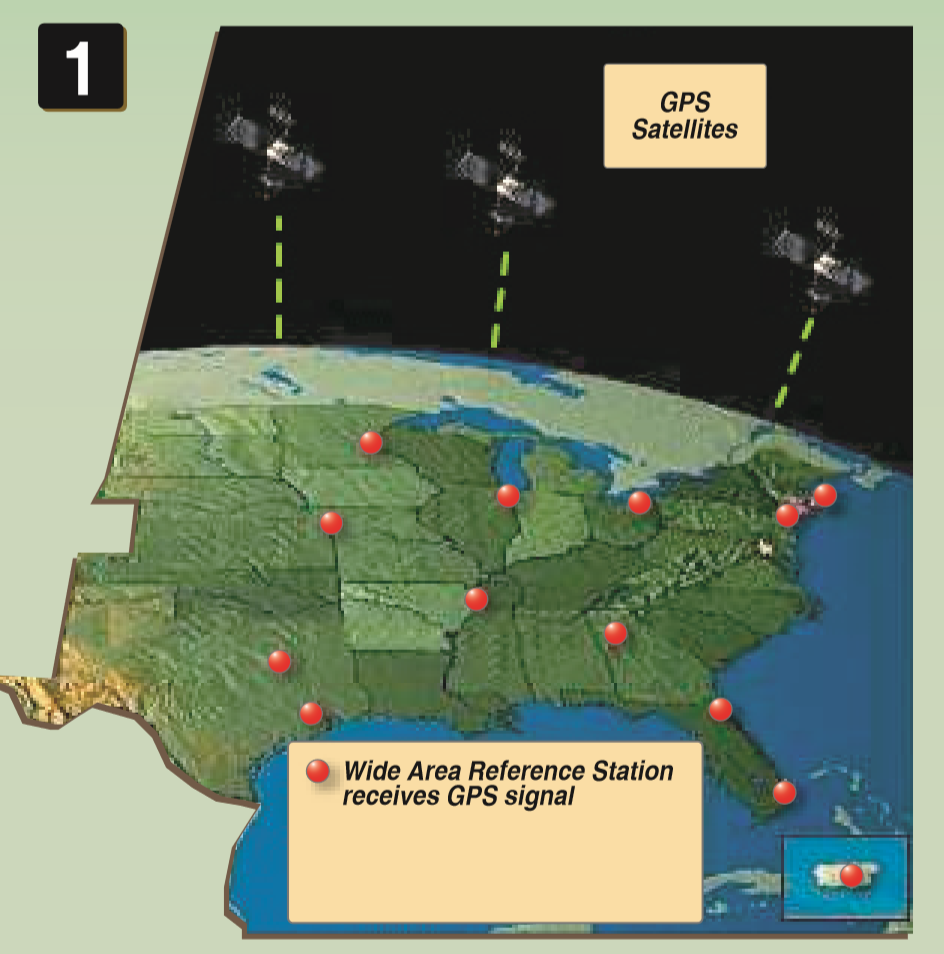
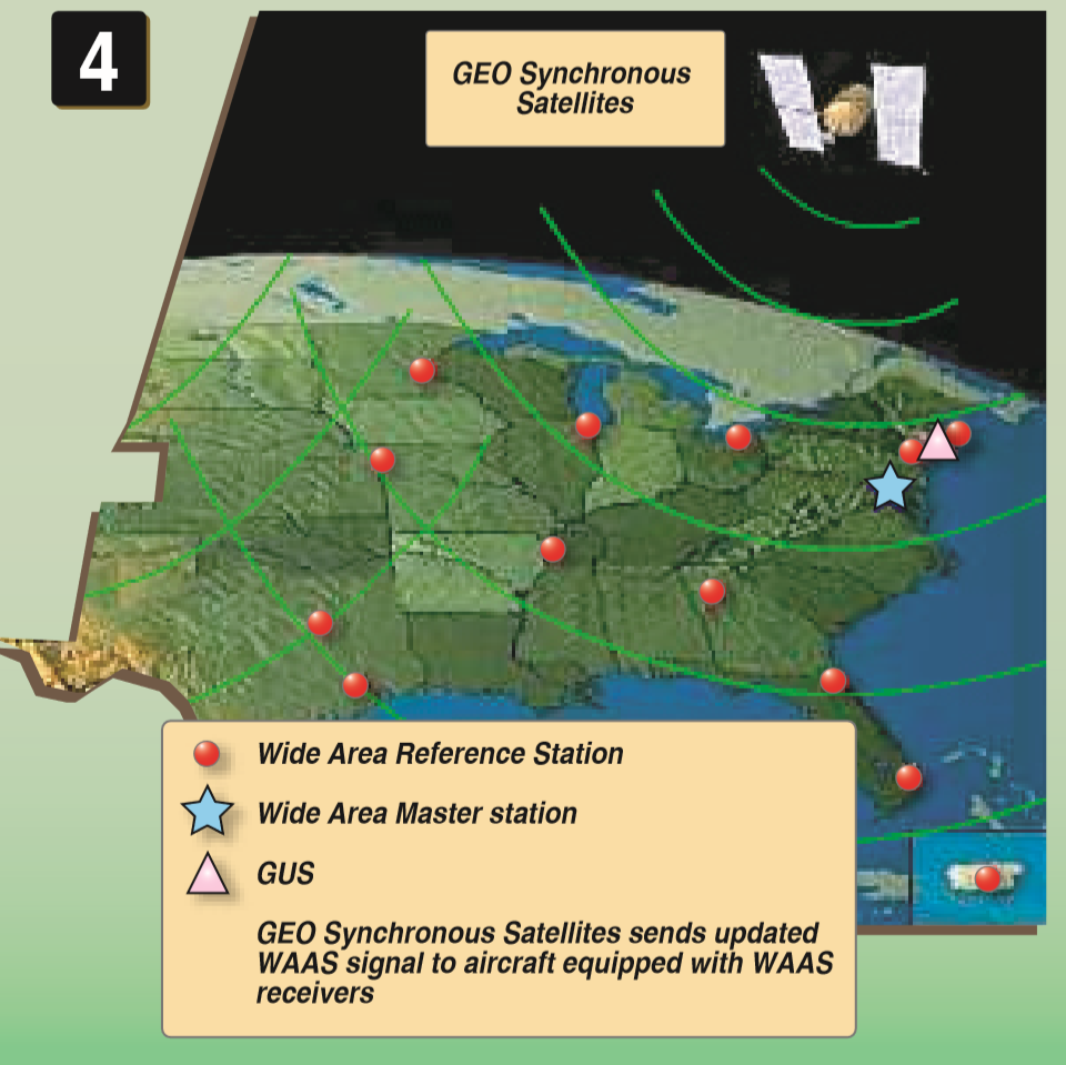
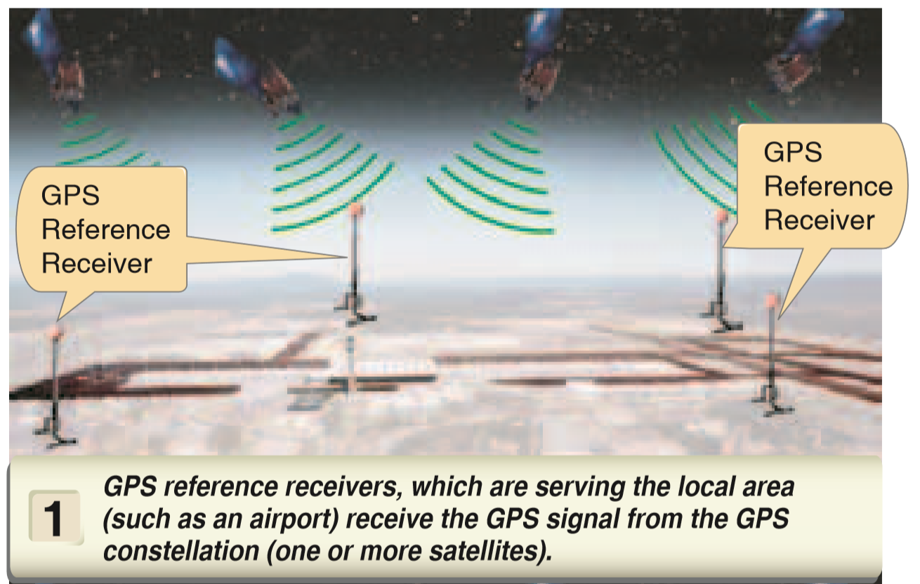
Wide Area Augmentation System (WAAS)
- WAAS is designed to improve the accuracy, integrity, and availability of GPS signals.
- Uses a series of ground stations that generate a corrective message that is transmitted to the airplane by a geostationary satellite.
Step 1 Click here
Step 2 Click here
Step 3 Click here
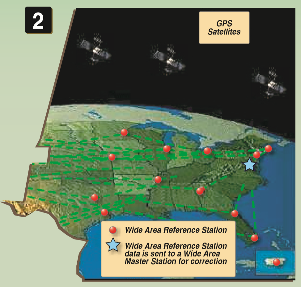
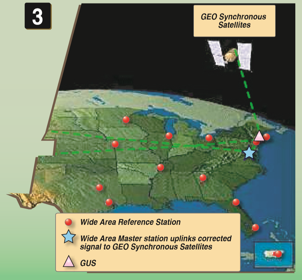
Step 4 Click here
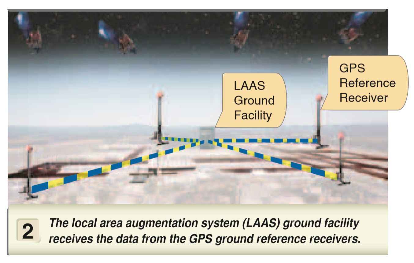
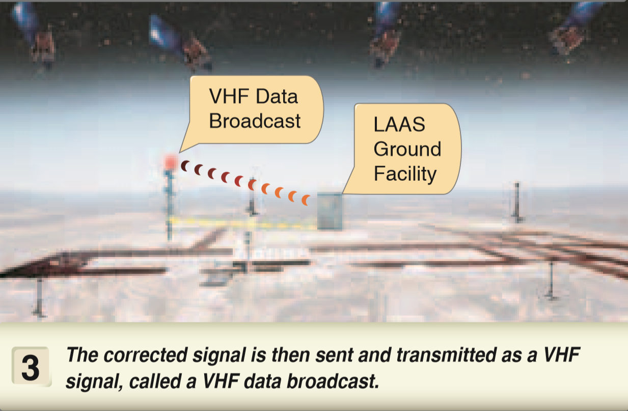
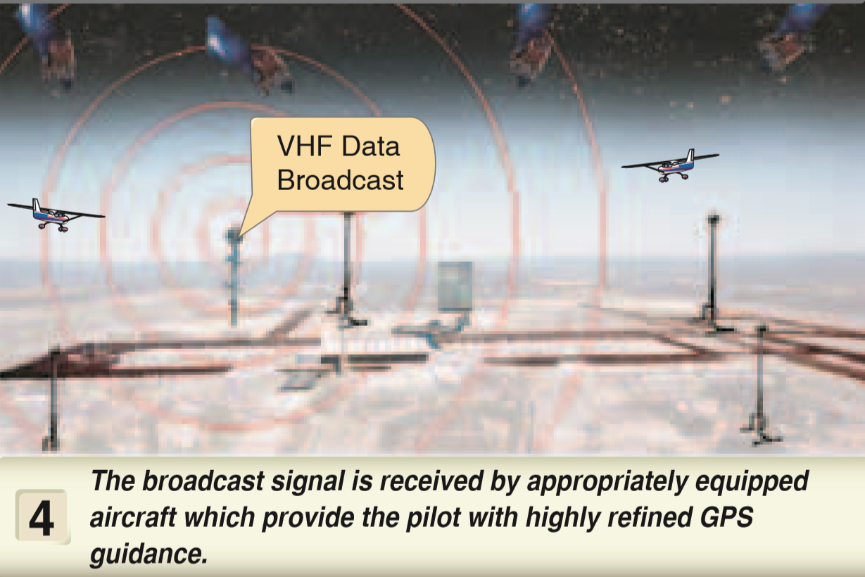
Ground-Based Augmentation System (GBAS)
- The ground-based augmentation system (GBAS), provides a GPS position correction even more precise than WAAS.
- Local receivers send corrections to an airport ground facility to broadcast the corrections signals to a compatible GBAS-GPS receiver to determine the correct position.
Step 1 Click here
Step 2 Click here
Step 3 Click here
Step 4 Click here
Requirements for IFR GPS Navigation
GPS use for IFR operations must be certified according to technical standard order (TSO).
GPS without WAAS is approved for IFR operations if updated to the last version of TSO-129.
TSO-129 / TSO-196
TSO 145 / TSO 146
- Non-WAAS equipped: aircraft must be equipped with alternate navigation equipment appropriate to the route to be flown.
- Lateral guidance during instrument approaches.
- If destination airport has only GPS approaches, a different type of instrument approach is required.
- WAAS equipped: aircraft does not required to have other equipment appropriate to the route to be flown.
- Ability to exclude bad GPS signal and continue operating.
- Vertical and lateral guidance during instrument approaches.
- If destination airport has only GPS approaches, no different type of instrument approach is required.
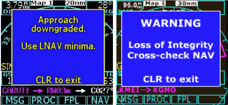
Receiver Autonomous Integrity Monitoring (RAIM)
- The system used to verify the usability of the received GPS signals and warns the pilot of any malfunction in the navigation system.
- This system is required for IFR-certified GPS units.
- Five satellites in view or four satellites and a barometric altimeter baro-aiding: RAIM will detect an integrity anomaly.
- Six satellites in view (or five satellites with baro-aiding): RAIM will isolate a corrupt satellite signal and remove it from the navigation solution.
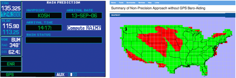
RAIM CHECK
-
Select AUX
-
Select RAIM Prediction
-
Enter Destination Aiport, Arrival Date, and Arrival Time
-
Select compute RAIM