GL 11 Navigation

Rev 12/2024
Disclaimer
Students should use their textbooks, syllabus, and Airman Certification Standards (ACS) as their primary sources of information. EcFlight is an online training tool designed to simplify and enhance your ground school learning experience. However, it is not a substitute for FAA- or school-approved study materials. Before using these slides for study, always refer to your officially approved resources, such as the Jeppesen physical or electronic book and other FAA-approved materials.
Reference Books
- Pilot's Handbook of Aeronautical Knowledge(FAA-H-8083-25B). (2016). Oklahoma City, OK: United States Department of Transportation, Federal Aviation Administration, Airman Testing Standards Branch.
- Private Pilot Syllabus (10001292-002). (2012). Englewood, CO: Jeppesen.
- https://www.faa.gov/about/office_org/headquarters_offices/ato/service_units/systemops/fs/res_links/media/icao_flight_plan_filing.pdf
- https://www.faa.gov/about/office_org/headquarters_offices/ato/service_units/air_traffic_services/flight_plan_filing/#dfpf
Reference Multimedia
- https://commons.wikimedia.org/wiki/File:Antennas_aircraft.svg
- https://blog.ucogear.com/prepare-for-a-power-outage-with-candle-lanterns-and-candles/
- https://commons.wikimedia.org/wiki/File:Coastal_refraction_NDB.png
- http://www.auroralchorus.com/ndb/ndbgllry.htm
- https://www.navpath.com/wp-content/uploads/2012/02/GNS-430-enroute.jpg
- Federal Aviation Administration . (2022, June). GPS How It Works. YouTube. https://www.youtube.com/watch?v=AiSuXDWbqs0
Index

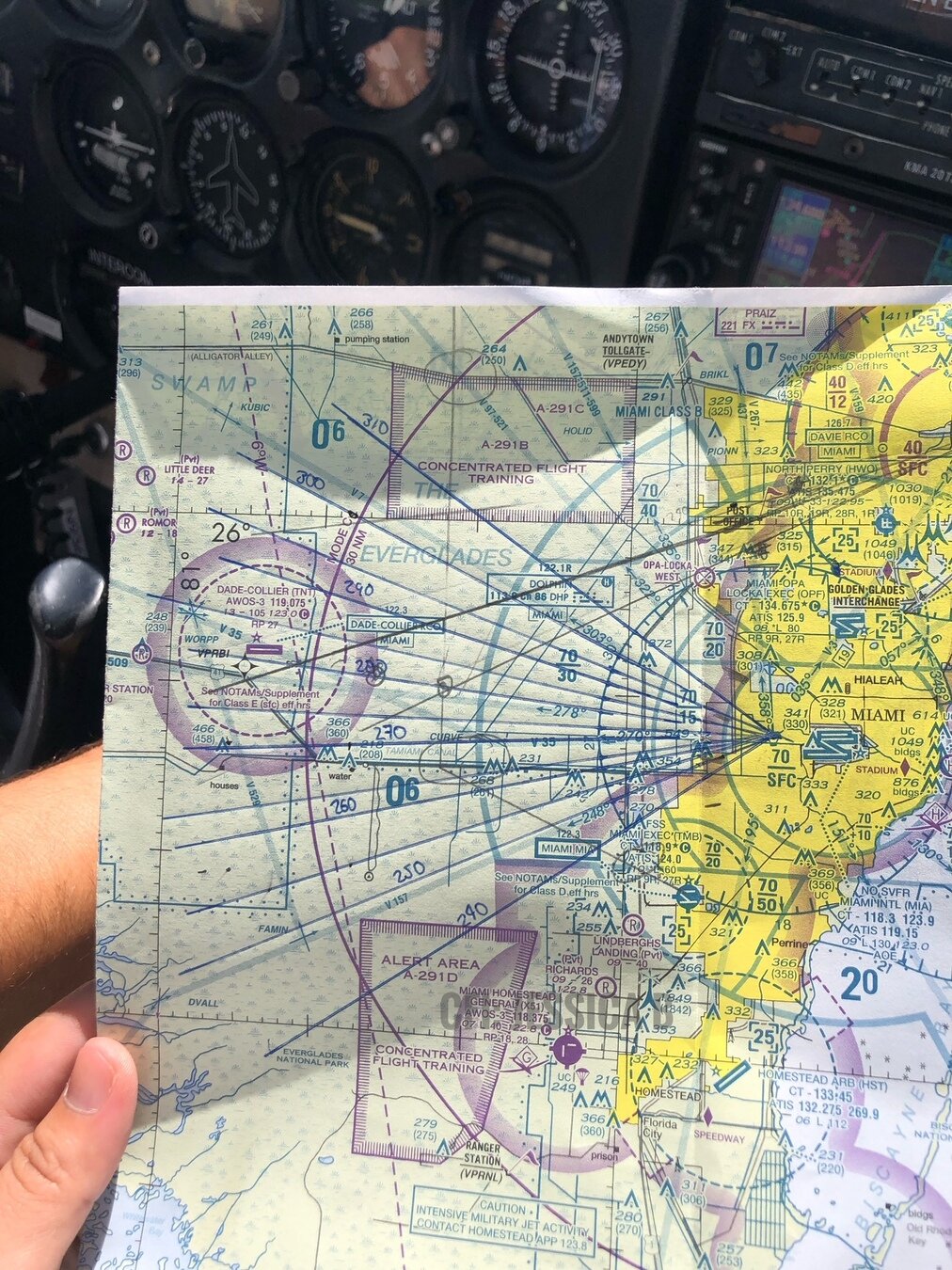
Pilotage and Dead Reckoning
Pilotage
- Pilotage is navigation by reference to landmarks or checkpoints.
- Commonly used in conjunction with dead reckoning and VFR radio navigation.
- Choose checkpoints that can be easily identified by other features such as roads, rivers, railroad tracks, lakes, and power lines.
Dead Reckoning
- Dead reckoning is navigation by computations based on time, airspeed, distance, and direction.
- The predicted heading takes the aircraft along the intended path.
- GS establishes the time to arrive at each checkpoint and the destination.
VFR Cruising altitudes
There many factors to consider when selecting your cruising altitude for cross country:
- Wind Direction/Speed
- Airspace
- Obstacles
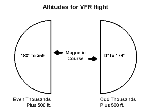
- Cruising flights more than 3,000 feet above the surface, you must comply with the VFR cruising altitude rule.
VFR Cruising Altitude
FAR § 91.159
- VFR aircraft on magnetic courses from 0° to 179° fly at odd thousand-foot altitudes plus 500 feet,
- Magnetic course from 180° to 359°, your choices for VFR is even odd thousand-foot altitudes plus 500 feet
Flight Planning
-
Doing as much as possible before each flight reduces workload, giving you more time to enjoy the flight and handle any problems.
-
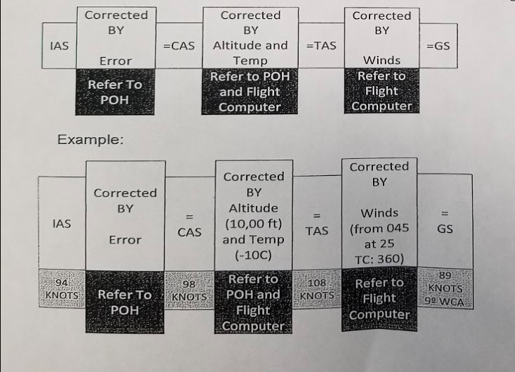
Dead reckoning is easier to handle when using a separate navigation log.
- The flight planning required for dead reckoning is a little more involved than that for pilotage.
Navigation Log form
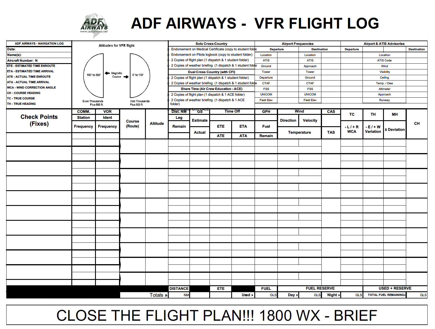
- Leg - may be any segment of the cross-country flight.
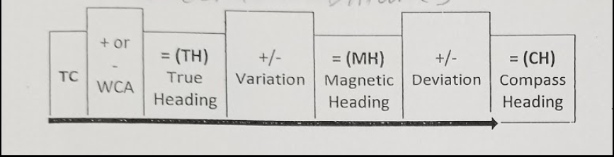
- Isogonic line - Local magnetic variation is shown on aeronautical charts by a dashed magenta line.
- Magnetic Course - is true course corrected for local variation.
- Magnetic Heading - is magnetic course corrected for the effects of wind.
- Compass Heading - magnetic heading corrected for compass deviation.
- Plot your course between checkpoints with a pencil.
1.
2.
3.
4.
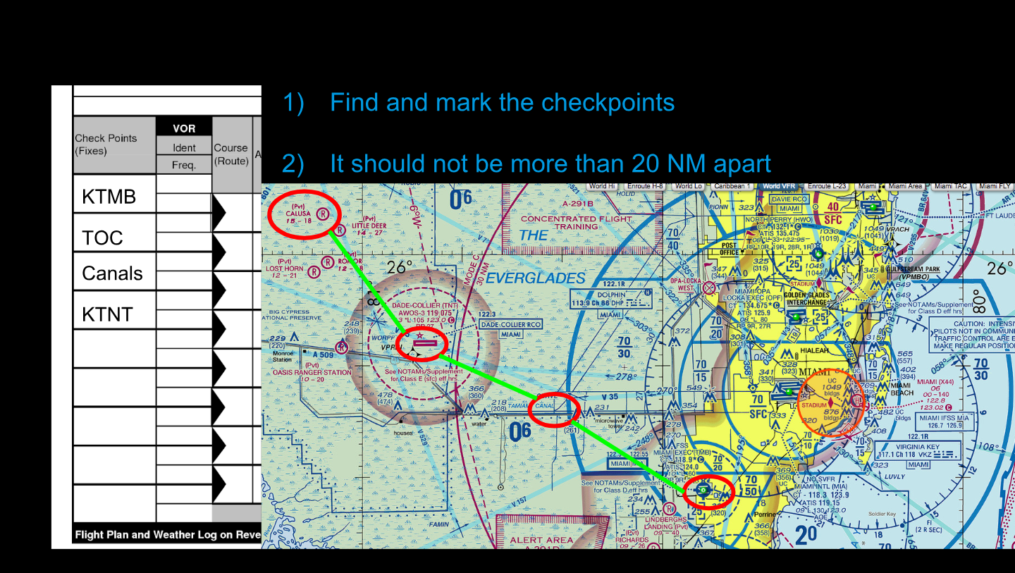
2). Distance between checkpoints should not be more than 25 Nautical Miles.
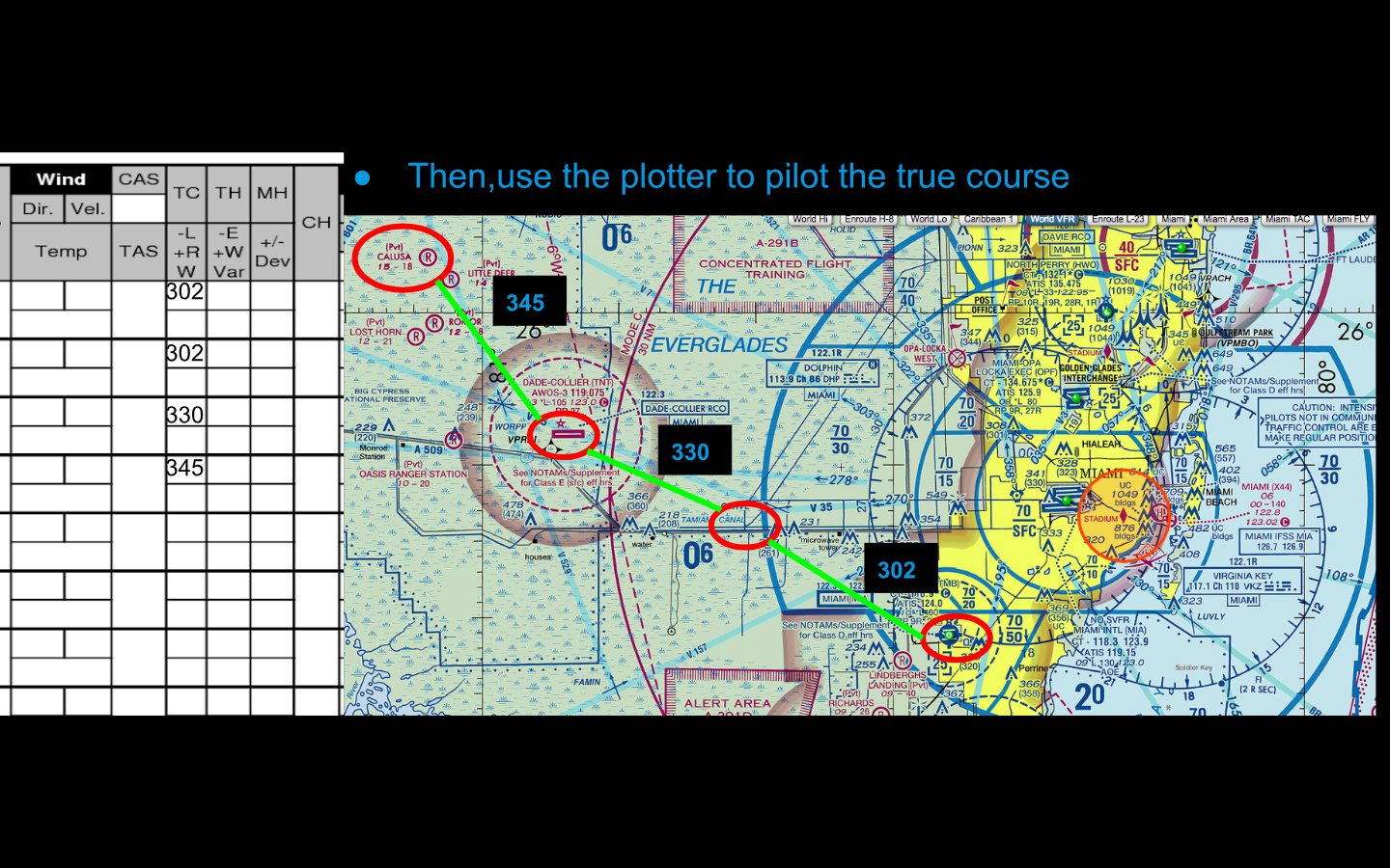
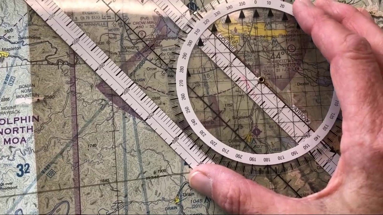
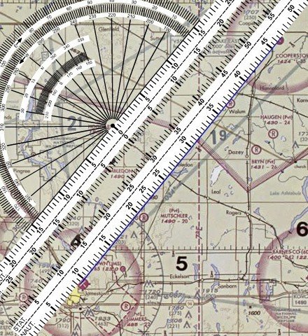
- Align the arrows pointing North of the plotter with the Longitude lines of the sectional chart to get the True course (TC).
Calculating the Top of Climb and Descend
C 172
Measure Distance
- Use a plotter to measure distances of each leg. Make sure you are using Nautical Miles, not Statute Miles.
15NM
Measure Distance
- Include the distances calculated in each leg on the Navigation Log. Try to maintain distances that do not exceed 25NM.
Determine Altitude
Follow FAR 91.159 VFR cruising altitude.
Remember this is based on Magnetic Course. Cruising altitudes need to be checked again at the end of the flight plan.
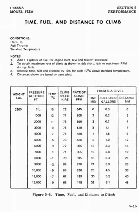
Determine Ground Speed
Read and follow the chart below to find ground speed.
Find Compass Heading
Read and follow the chart bellow to find Compass heading.
How to find Magnetic Heading?
Step 2 Find Compass Heading
- Inside the compass, there are compensating magnets to counteract the magnetic interference generated by our instruments.
- A compass card is typically attached, showing what error correction to add for different headings, although the changes usually are just a few degrees.

Determine Time in-route (ETA)
Cruise Performance Chart
Find Fuel Consumption (GPH)
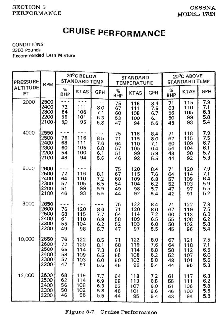
- Use your POH to calculate fuel consumption during cruise flight.
- Then, find the fuel reserve: "30 minutes during the day and 45 minutes during the night."
- Day VFR flights enough fuel to fly to the first point of intended landing and to fly after that for 30 minutes
- At night: +45 minutes
Fuel Requirement
FAR § 91.151
VFR Flight Plan
-
The VFR flight plan is a request that the FSS initiate a search for you if they have not heard from you by a certain time.
- When you file a flight plan with an FSS, a record is made that includes your destination, route of flight, arrival time, and the number of people aboard the airplane.
-
Once airborne, you activate your flight plan by radio so the FSS can keep track of your airplane’s estimated arrival time.
- If you do not close or extend your flight plan within 30 minutes after your stated ETA, the FSS will begin a search by telephone and then notify search and rescue organizations.
Flight Plan
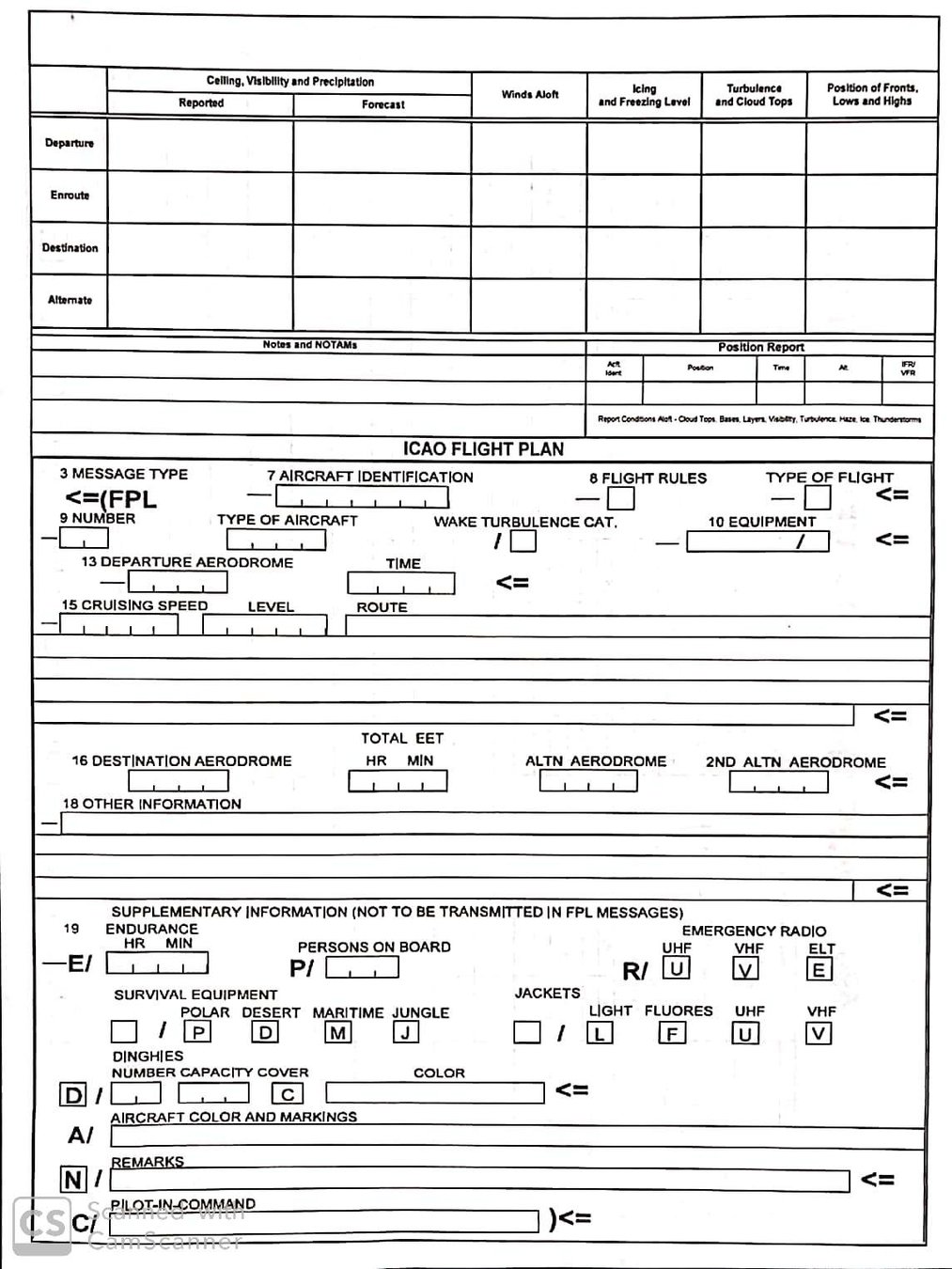
Click on each section to get more information about filling the ICAO Flight plan.
7. Aircraft Identiication
Enter Aircraft Identification. For example: N123EC.
8. Flight Rules and Type of Flight
Flight Rules: IFR or VFR
Type of flight:
- S if scheduled air service
- N if non-scheduled air transport operation G if general aviation
- M if military
- X if other than any of the defined categories above
9. Number and type of flight/ Wake turbulence Catergory.
Type: C172
Wake turbulence category:
- L – LIGHT, to indicate an aircraft type with a maximum certificated take-off mass of 15,500 lbs or less.
- M – MEDIUM. A maximum certificated take-off of fewer than 300,000 lbs.
- H – HEAVY. Maximum certificated take-off mass of 300,000 lbs or more.
10. Equipment and Capabilities
| S (Standard) | D (DME) | G (GNSS) |
|---|---|---|
| I ( INS ) | O (VOR) | R (PBN ) |
| T (TACAN) | W (RVSM) |
Enter radio communication, navigation and approach aid equipment and capabilities. After / enter surveillance equipment and capabilities.
Example: C (Transponder, Mode C)
Note: A complete listing of Aircraft COM, NAV, and Approach Equipment Qualifiers can be found in the AIM table 5-1-4.
s c
13. Departure Aerodrome and Time
- DEPARTURE AERODROME: Insert the ICAO identifier of your departure airport.
- TIME: Enter the estimated departure time.
15: Cruising Speed/Level/Route
-
CRUISE SPEED: Cruising Speed ENTER the expected cruising speed as:
N followed by 4 digits (for Knots) (e.g. N0125 for 125 knots).
-
LEVEL: Insert the planned cruising altitude in hundreds of feet for the first or the whole portion of the route to be flown expressed as A followed by 3 figures (e.g. A075 for 7,500 feet MSL).
-
ROUTE: Insert your intended route of flight.
-
Do not include the departure and destination in the route field.
-
When planning direct from one fix to another, use DCT between the fixes
-
16. Destination Aerodrome and Total Estimated Elapsed Time, Destination Alternate Aerodrome(s)
-
DESTINATION AERODROME:
-
Insert the ICAO identifier of your destination airport.
-
-
TOTAL EET (Estimated Elapsed Time):
-
Insert your total estimated elapsed time (your time en route).
-
-
ALTERNATE AERODROME:
-
Insert the ICAO identifier of any alternate airports (optional).
-
18. Other information
The Other Information field is where you enter additional indicators required by FAA or ICAO rule.
Insert 0 (zero) if no other information.
19. Endurance/Color/Persons on Board/PIC
-
Endurance: ENTER a 4-figure group giving the fuel endurance in hours and minutes.
-
Persons on board: ENTER the total number of persons (passengers and crew) on board.
-
A/ (AIRCRAFT COLOR AND MARKINGS): ENTER color of aircraft and significant markings.
-
C/ (PILOT): ENTER name and contact information of pilot-in-command. Other items may be filled in at the pilot’s discretion.
How to file your flight plan
- Call Flight Services (1-800-WX-BRIEF or 1-800-992-7433) – The flight services specialist will file your flight plan.
- Submit your plan online through one of the following free services:
How to open / close a VFR flight plan
- The flight plan must be activated or otherwise, will be deleted off the system after 1 hour of the expected departure time.
- The flight plan can be activated through FSS by radio or telephone, or online by using 1800wxbrief.com filing services. Next slide will show a demonstration on how to do it.
- Close the flight plan upon arrival by calling 1800-wxbrief or online. If the flight plan is not closed no 30 minutes after your ETA, Search and Rescue will be sent to look for your aircraft.
Demonstration
Lost Procedures
Whenever you are lost, during your cross-country journey, or even in the alert area, the remembrance of the Five C's will help you find your position by complying with the following:
C
C
C
C
C
Climb
Circle &
Confess &
Comply
Conserve
C
Cross radial
C
Communicate
- Better radio and nav aid reception.
- Increased radar and DF coverage.
- Better view of the landmarks.
- Maintain your original heading
Climb
-
Around the area to look for landmarks on the chart and avoid areas of higher terrain.
Circle
Cross Radial
-
Use two nearby VOR stations, and center both with a FROM indication, to determine your position.
- Draw the lines from the VORs and the point where these two lines are intersecting is where you are.
- Confess that you are lost when contacting ATC or another ground facility.
- if your situation is threatening, clearly explain your problem, using the emergency frequency 121.5 MHz, if necessary.
Confess
- Contact any nearby facilities and know the frequencies that can help such as the nearest control tower, flight service station, departure, lost guard.
Communicate
- Comply with assistance instructions. If not sure, ask for explanations. Never assume.
Comply
Conserve
- Consider reducing power setting to conserve fuel. In addition, ensure that the mixture is leaned properly to extend your range and endurance.
VOR Navigation
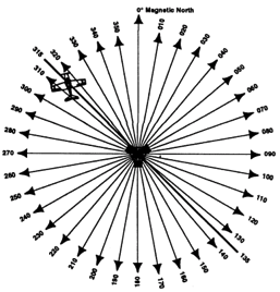
1) VOR ground stations transmit within a VHF frequency band of 108.0–117.95 MHz.
2) The prefix “Omni-” means all, and omnidirectional projects straight line courses (radials) from the station in all directions.
- Radials are identified by numbers beginning with 001.
3) Range Limited. Divided into different service volumes of VOR.
(Very High Frequency-Omni Directional-Range)
Ground Equipment
VOR
VOR provides magnetic bearing information TO and FROM the station.
(Very High Frequency Omni Directional Range)
Ground station Projects straight line courses (radials) from the station in all directions. Two signals provide complete information to the aircraft: Reference signal and Rotating signal.
Aircraft equipment senses the time between the rotating signal and the reference signal and deflects the needle set on the NAV display or CDI selector.
Airborne Equipment
Consists of:
- Antenna
- Receiver
- Indicator
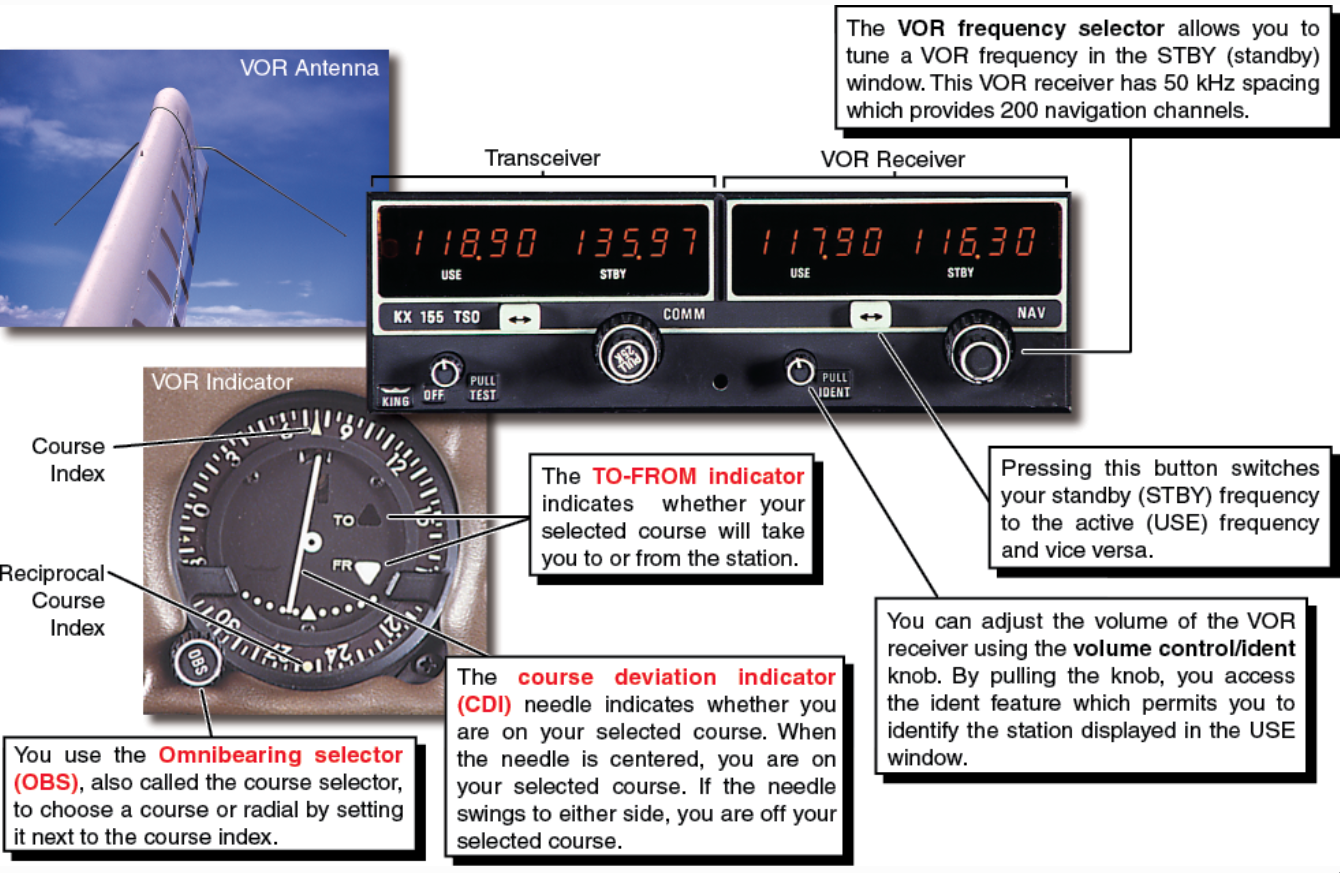
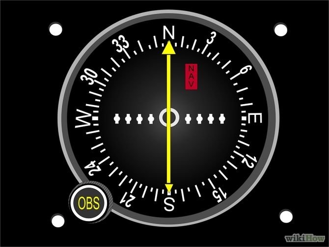
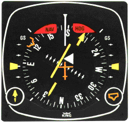
- The VOR indicator consists of the course deviation indicator (CDI), the TO-FROM indicator, and the omnibearing selector (OBS), or course selector.
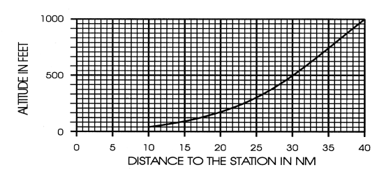
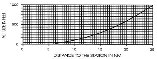
Service Volumes: VOR is limited by ranges depending on the Type of VOR in use starting from 1,000ft.
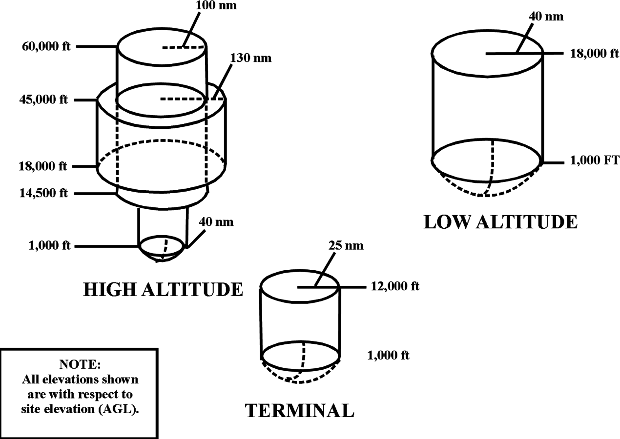
Legacy Service Volumes
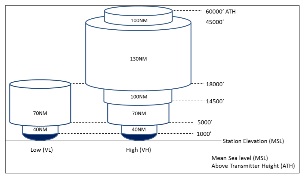
New Service Volumes
Present in three different Navigation aids (NAVAIDs)
- VOR: Does not provide distance from station
- VOR/DME: DME is also installed with a VOR. will provide Distance from station.
- VORTAC: When military tactical air navigation equipment is installed with a VOR (TACAN). DME is always an integral part of a VORTAC.
Navigation Procedures
VOR is a relatively easy navigation system to use once you understand the basic navigation procedures. These operations include:
- Tuning and identifying a station
- Interpreting VOR indications
- Tracking
- Intercepting a course
- Cross checking your position.
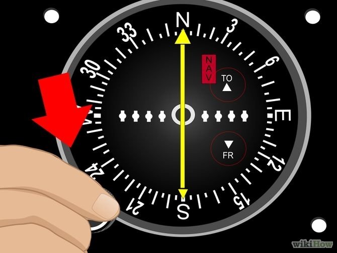
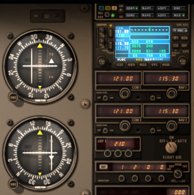
Verify VLOC mode is ON
If your aircraft is equipped with GPS
Identifying a Station
Tune your VOR receiver and identify the station to ensure you have chosen the right frequency and that the station is working properly.
If you do not hear the VOR’s Morse code identifier or voice identification, you cannot assume a reliable navigation signal.
Interpreting VOR Indications
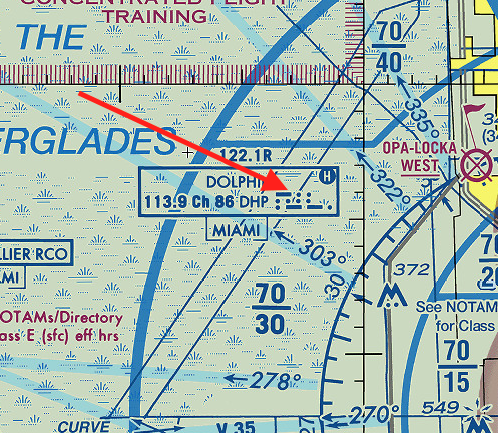
- To determine your position relative to the station, turn the omnibearing selector (OBS) knob until the course deviation indicator (CDI) needle centers with a FROM indication and read the resulting radial next to the index mark on the top of the VOR indicator.
- The area over the station in which the TO-FROM indicator changes is called the cone of confusion, or no-signal area.
Tracking
When tracking, you maintain the selected course by keeping the CDI centered.
Intercepting a course
- Course interceptions are performed in most phases of instrument navigation. The equipment used varies, but an intercept heading must be flown that results in an angle or rate of intercept sufficient for solving a particular problem.
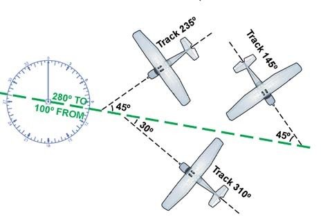
- Remember that in some situations, you may need to track to the station on a different course instead of flying direct from your present position.
Turn the omnibearing selector (OBS) knob until the course deviation indicator (CDI) needle centers with a FROM indication and read the resulting radial next to the index mark on the top of the VOR indicator.
Cross Checking Your Position
When you determine your radial from a station, you only establish that your location is on a line of position extending away from the station.
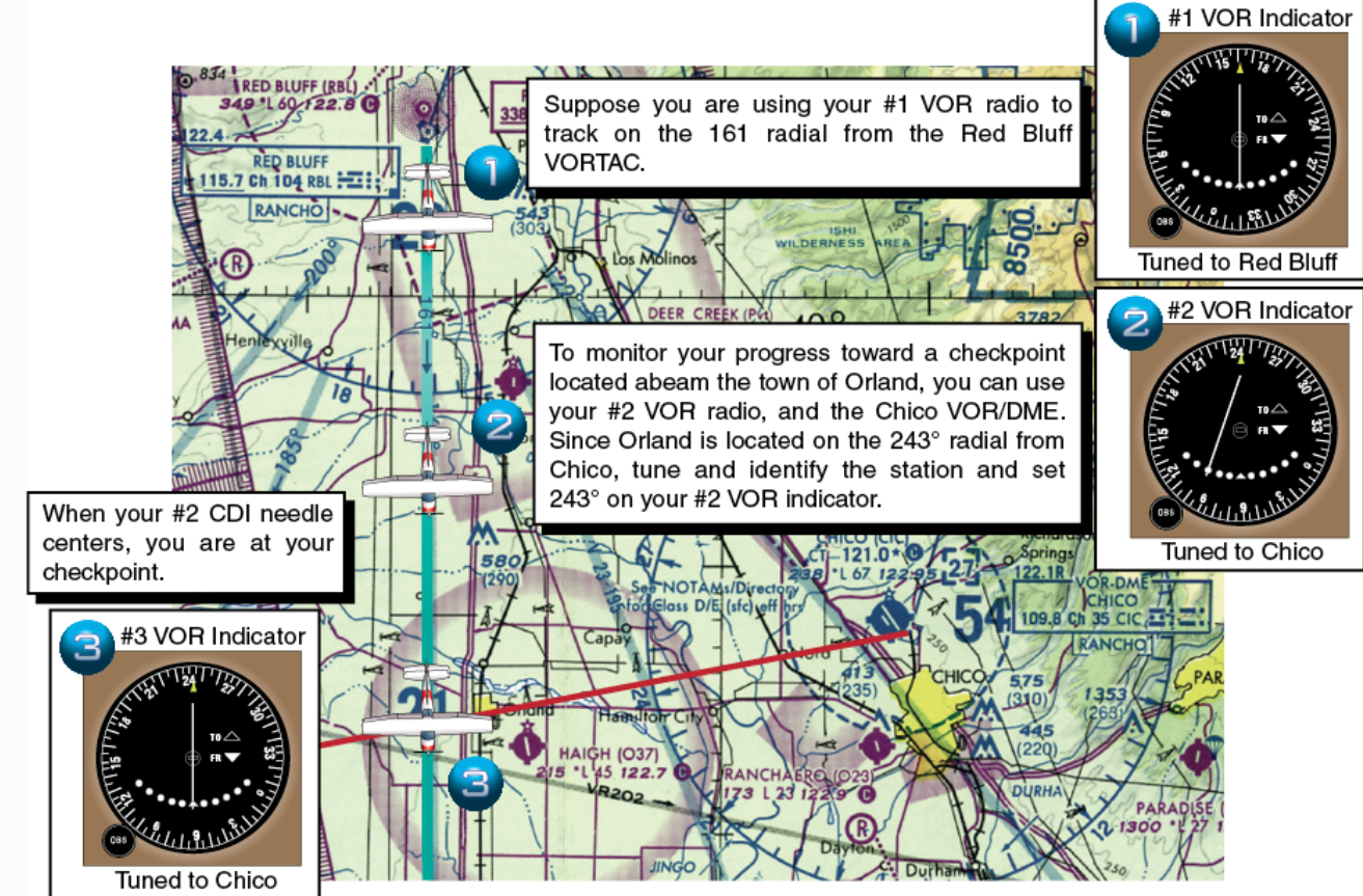
You can determine your exact position by cross checking with a second VOR station, this is called triangulation
VOR Navigation
Checking VOR Accuracy
-
The accuracy of course alignment of VOR radials is considered to be excellent. However, certain parts of the VOR receiver equipment deteriorate, and this affects its accuracy.
- VOR accuracy checks are not a regulatory requirement for VFR flight. The VOR Check must be done every 30 days.
Checking VOR Accuracy (30Days)
Vot - +/- 4 specific station on the ground, check AF/D.
Bench - only by a mechanic.
Ground - +/- 4 specific places in the airport, check AF/D.
Airborne - +/- 6 using specific checkpoints, check AF/D.
Inflight - +/- 6 using Victor airways
Dual - not exceed 4 between 2 VOR receivers.
VOT (Test Facilities)
- Can Be used in most locations of an airport.
- VOT facilities transmit only one radial. Tune and identify the frequency and set the course selector to 180° with a TO indication or 360° with a FROM indication. The needle should center, +/- 4°.
FROM
TO
Bench (Mechanics)
Bench checks are performed by an authorized Mechanic (A&P).

Ground and Airborne Checks
- Ground and airborne checks should be received at specific points on the airport surface or over specific landmarks while airborne in the immediate vicinity of the airport.
- Locations of these checkpoints are published in the A/FD. Error Tolerance +/- 4°.
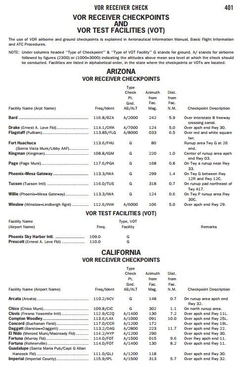
Inflight Checks
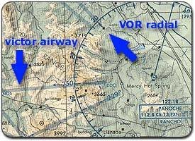
- Select a VOR radial that defines the centerline of an airway. Then, locate the prominent terrain feature with the sectional chart (Preferably more than 20NM from the station).
- Error Tolerance is +/- 6°.
Dual Checks
- If a dual system VOR is installed in the aircraft, one system may be checked against the other.
- Turn both systems to the same VOR ground facility and note the indicated bearing to that station. The maximum permissible variation between the two indicated bearings is 4°.
VOR Operational Considerations
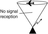
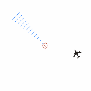
Cone of confusion: A cone-shaped volume of airspace directly above a VOR station where no signal is received, causing the CDI to fluctuate.
Demonstration
The line of Sight: VOR uses VHF signals they are susceptible to Obstacles and aircraft might not be able to receive signal.
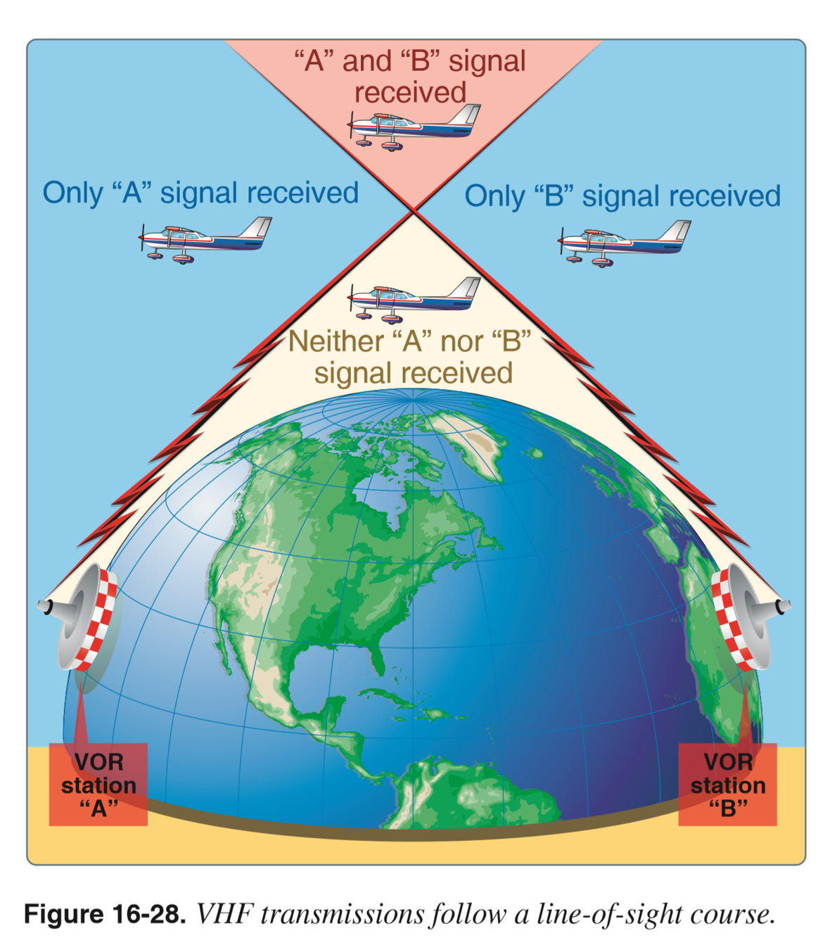
Service Volumes: VOR is limited by ranges depending on the Type of VOR in use starting from 1,000ft.
New Service Volumes
Legacy Service Volumes
But what about below 1,000 feet?
High And Low VOR
Terminal VOR
You can still receive signal depending on the aircraft's altitude.
Airborne Equipment Error: Caused By magnetic interference inside the aircraft like the GPS or Radios.
Zone of Ambiguity
Reverse Sensing
Horizontal Situation Indicator
(HSI)
The HSI combines a heading indicator and VOR indicator in a single display, This reduces pilot workload by lessening the number of elements in the pilot's instrument scan to the six basic flight instruments.
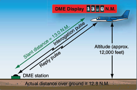
Distance Measured Equipment (DME)
- Enables you to keep track of your distance to or from a VOR, TACAN or VORTAC.
- DME gives you SLANT RANGE DISTANCE to the station.
- Can be received up to 199 NM from the station.
DME is required above FL240
- Aircraft send pulses to the station, then the station transmits pulses back, the time this process takes is measured in the DME unit and is translated into a distance in NM.
DME Considerations
- An error is caused by the DME since the signal travels in a straight line to and from the ground station.
- DME is accurate when you are at least one horizontal mile from the station for every 1.000 feet above the field elevation.
ADF Navigation
NDB Navigation
Navigation using nondirectional radio beacons (NDBs) is the oldest form of electronic navigation still in regular use. In the early days of aviation, the process of navigating between these beacons, called radio direction finding, required positioning the airplane’s antenna to receive and interpret bearing information with the ADF.
Ground Equipment
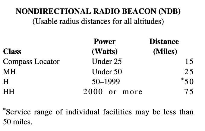
- To navigate using the ADF, the pilot tunes the receiving equipment to a ground station known as a nondirectional radio beacon (NDB).
- The NDB stations normally operate in a low or medium frequency band of 200 to 415 kHz.

- Since NDB signals are not limited to line of sight, the ADF system provides reliable navigation at lower altitudes than VOR equipment. In addition to NDBs, your airborne ADF equipment also can receive AM commercial broadcast stations.
- The following table gives the class of NDB stations, their power, and their usable range:
Airborne Equipment
-
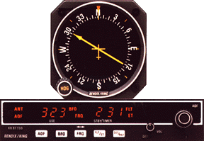
ADF equipment in the aircraft permits L/MF signals to be received through the antenna, relayed to the ADF receiver where they are processed, and then sent to the ADF bearing indicator.


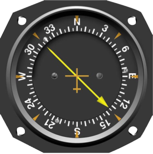
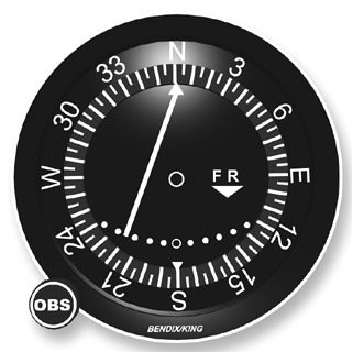
Moveable Card ADF.
Fixed Card ADF
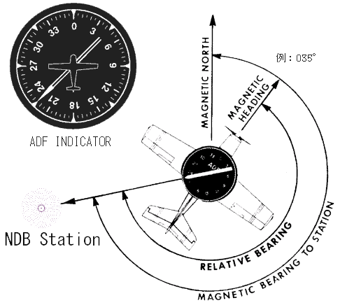
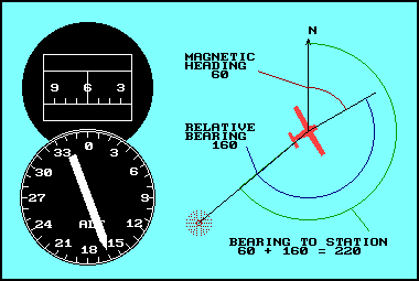
MH + RB = MB
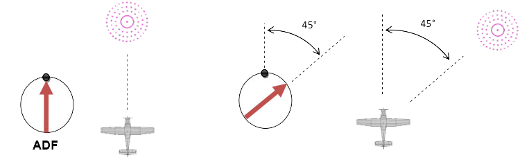
Types of ADF Receivers
Movable-Card Indicator
- When you set your magnetic heading value under the top index of a movable-card indicator, the head of the ADF needle will directly indicate magnetic bearing to a station.
- In addition, the number under the tail of the needle indicates magnetic bearing from the station.
- The movable card reduces your workload since it does not require you to use the ADF formula to find the magnetic bearing.
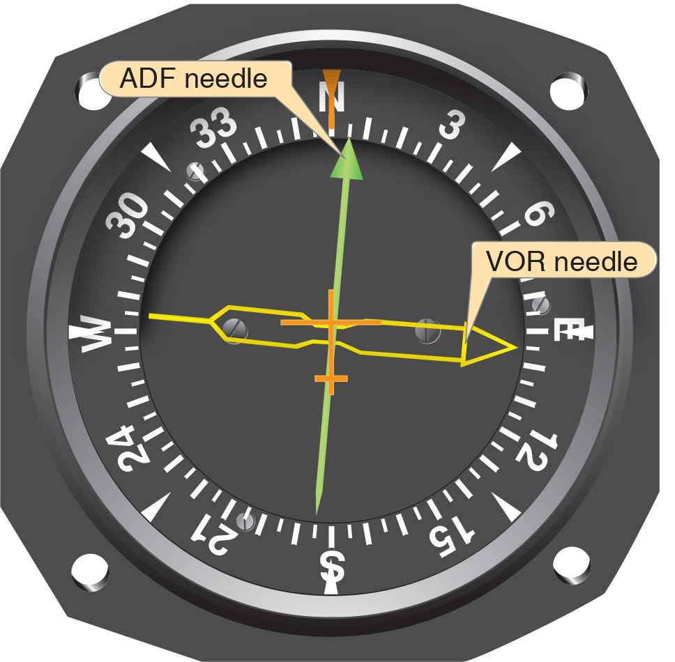
Radio Magnetic Indicator (RMI)
The RMI is a navigational aid providing aircraft magnetic or directional gyro heading and very high-frequency omnidirectional range (VOR).
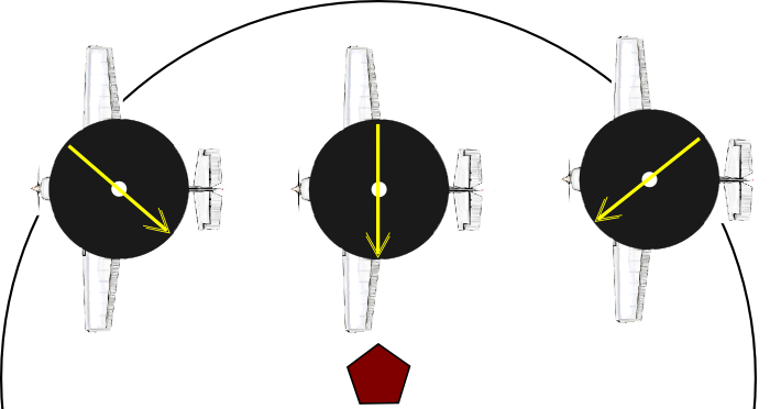
Intercepting a Bearing
Intercepting a specific bearing to track to or from an NDB is accomplished by a method similar to that used in VOR navigation. Use the ADF formula to help you with this procedure.
MH + RB = MB
Tracking
Normally, the best way to fly to or from a station is in a straight line, which requires tracking if any crosswind is present. The tracking procedure for an ADF is similar to VOR tracking.
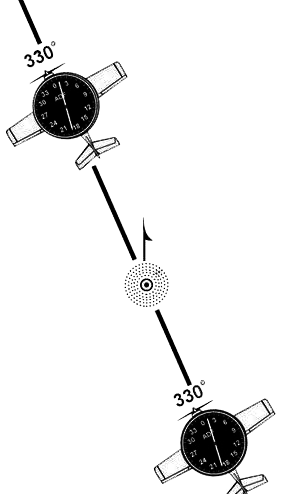
Homing
A procedure during which you always keep the nose of the aircraft pointing directly to the station is called homing to the station. To fly to an NDB using the homing procedure simply turn to position the head of the ADF needle on the aircraft’s nose
Operational Considerations
-
ADF indicator does not have an OFF flag, it is possible to inadvertently refer to the signal after it is no longer reliable.
-
One way to make sure you have a usable signal is to leave the identifier turned up to an audible level whenever you use the ADF for navigation.
-
Also, some limitations are:
- Night Effect
- Thunderstorm Effect
- Precipitation Static
- Terrain Effect
- Shoreline Effect
Night Effect
- NDB signals can be refracted by the ionosphere and return to earth 30 to 60 miles or more from the station, leading to ADF needle fluctuations.
Thunderstorm Effect
Needle tends to point to the source of the lightning flashes rather than the tuned NDB.
Precipitation Static
By a buildup of static electricity on an aircraft flying in rain, snow, or clouds.
Terrain Effect
Can occur when mountains reflect the radio waves and cause erroneous bearing indications.
Shoreline Effect
Radio waves speed up over water, causing the wave front to bend away from its normal path and pull it towards the coast.
Satellite Navigation GPS
-
Area Navigation (RNAV) is any equipment that computes the aircraft position, actual track, and groundspeed and then displays the distance and time estimates to the selected waypoint.
-
Waypoints are predetermined geographical positions for a route without using ground facilities.
- Examples are: GPS, VOR/DME RNAV Inertial navigation system (INS).
GPS Operation
- The GPS is a satellite-based radio navigation system that broadcasts a signal that is used by receivers to determine precise position anywhere in the world.
- The constellation of satellites providing a high-frequency signal that contains time and distance and is picked up by a receiver is called the Global Navigation Satellite System (GNSS)
How does GPS work
Composed of three elements:
Space Component
User Component
Control component
Space Component
- Consists of 31 satellites in 6 orbital planes and spaced 55° apart for complete coverage.
- The satellites broadcast a pseudo-random code timing signal and data message that the aircraft equipment processes to obtain satellite position. By knowing the satellite position, GPS receivers are able to determine the aircraft's exact position.

Space Component
- The aircraft receiver measure the time each satellite signal takes to arrive, therefore, determine aircraft position.
- Each satellite contains four atomic clocks. These clocks are accurate to at least a billionth of a second or a nanosecond.
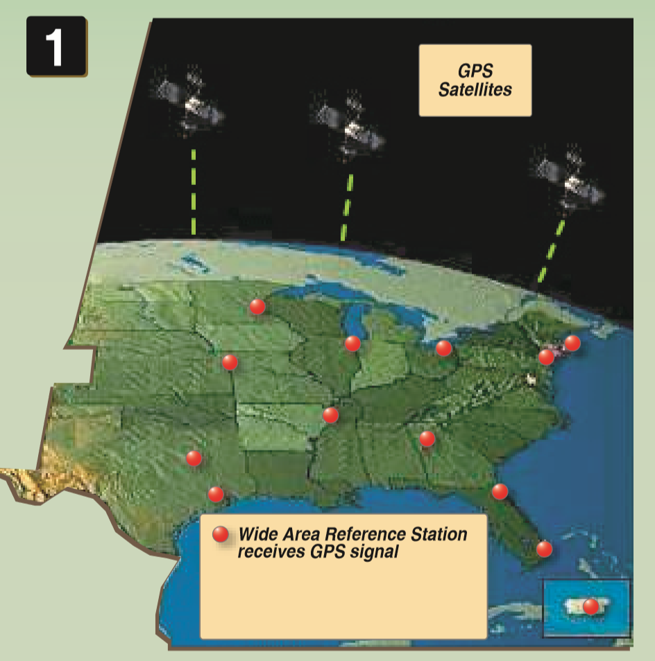
Ground Component
- Consists of a network of ground-based GPS monitoring and control stations that ensure the accuracy of satellite positions and their clocks.
User Component
- Consists of antennas and receiver on board the aircraft that provide positioning, velocity, and precise timing to the user.
- GPS equipment used while operating under IFR operation must meet the standards in Technical Standard Order (TSO).
Overview of GPS
Trilateration
Trilateration is the process by which the GPS receiver establishes a position.
- Trilateration Process: The GPS receiver calculates its position by determining its distance from at least three satellites.
- Precise Timing: Satellites use atomic clocks to transmit radio signals, which travel at the speed of light (186,000 miles per second).
- Distance Calculation: Distance equals signal travel time multiplied by the speed of light.
- Role of the Fourth Satellite: A fourth satellite corrects timing errors caused by the less precise clocks in GPS receivers, ensuring accurate position calculation.
- Accuracy: GPS guarantees positioning accuracy within 15 meters or less.
How it works?
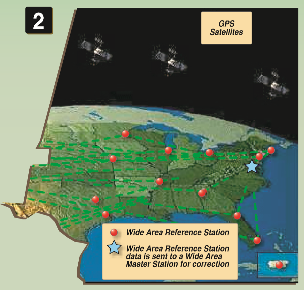
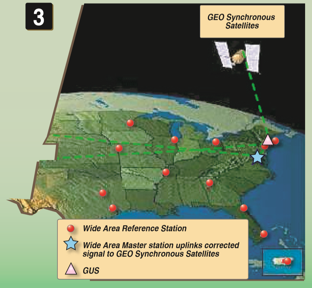
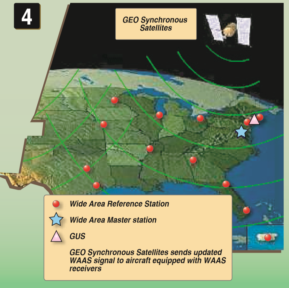
Wide Area Augmentation System (WAAS)
- WAAS is designed to improve the accuracy, integrity, and availability of GPS signals.
- Uses a series of ground stations that generate a corrective message that is transmitted to the airplane by a geostationary satellite.
Step 1 Click here
Step 2 Click here
Step 3 Click here
Step 4 Click here
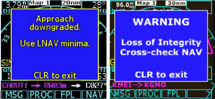
Receiver Autonomous Integrity Monitoring (RAIM)
- The system used to verify the usability of the received GPS signals and warns the pilot of any malfunction in the navigation system.
- This system is required for IFR-certified GPS units.
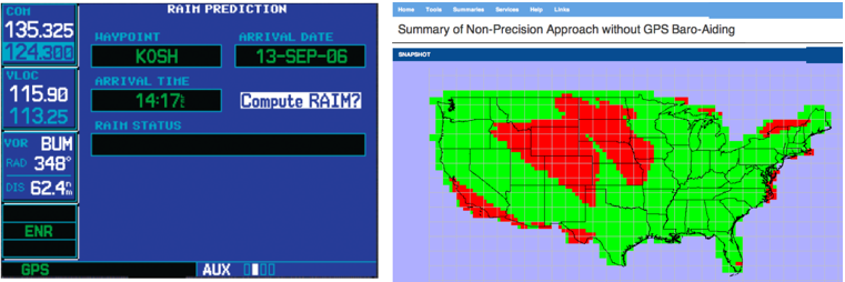
- Five satellites in view or four satellites and a barometric altimeter baro-aiding: RAIM will detect an integrity anomaly.
- Six satellites in view (or five satellites with baro-aiding): RAIM will isolate a corrupt satellite signal and remove it from the navigation solution.
RAIM CHECK
-
Select AUX
-
Select RAIM Prediction
-
Enter Destination Aiport, Arrival Date, and Arrival Time
-
Select compute RAIM
Navigating with GPS
Navigating with GPS
GPS Equipment
- Many GPS units are classified as flight management systems (FMS).
-
An FMS is a computer system equipped with a database that allows for the programming of routes, approaches, and departures, as well as calculating flight data such as fuel consumption and remaining time.
There are a variety of GPS displays; you🫵🏽 must become familiar with the GPS equipment that you are operating.
Navigation Database
-
GPS navigation database has to be updated every 28 days.
-
Obstacle database has to be updated every 56 days.
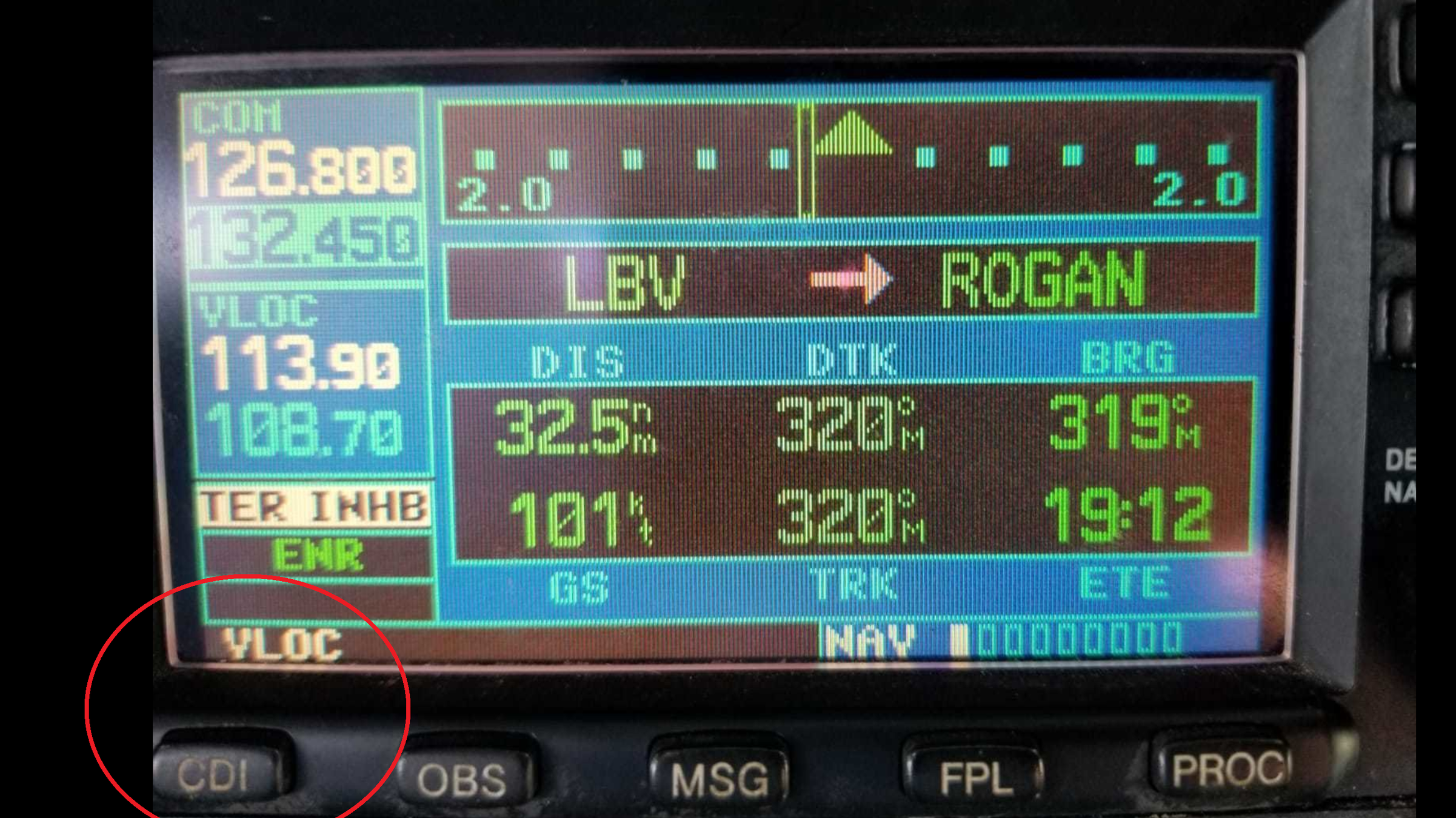
Course Deviation Indicator (CDI)
Press the CDI button to change the VLOC mode to the GPS mode.
Moving Map
-
The moving map is a good tool for controlled flight into terrain (CFIT).
- With the moving map, you gain automatic situational awareness in four dimensions (time being the fourth), along with graphical and dynamic mapping of weather systems, airway and airport data, and so much more.
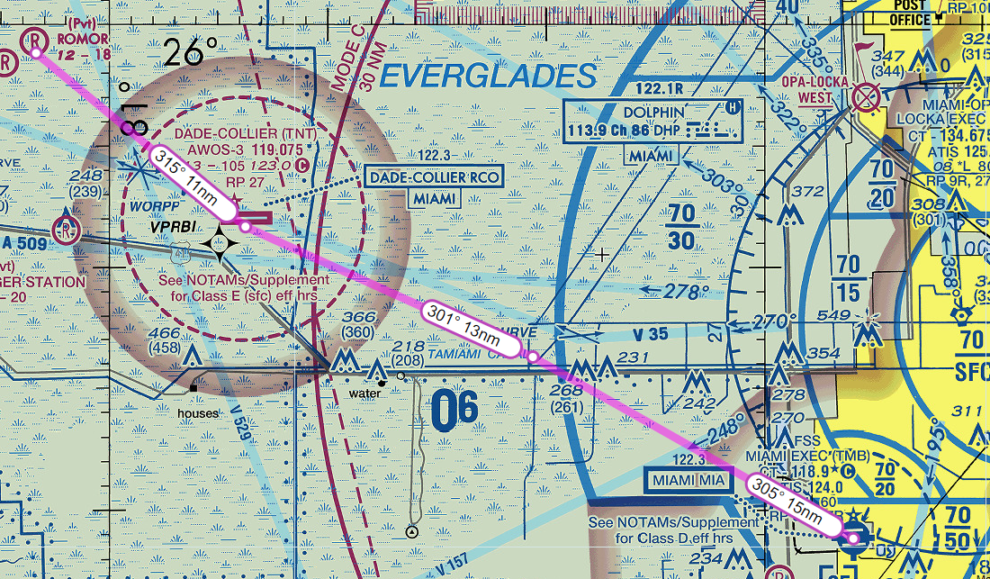
Waypoints
- VFR Waypoints
- A specified geographical location used to define an area navigation route or the flight path of an aircraft employing area navigation. Can be seen on VFR sectional charts
GPS Flight Planning
-
As a pilot, you can preplan your flight by inputting nearest GPS waypoints or nav aids in the GPS.
- This can be found under the navigation section in the GPS.
Navigation Data
- Due to satellite broadcasts, ranging signals, and navigation, pilots can estimate their position, velocity, and time en route.
-
The receiver uses data from at least four satellites above the mask angle (the lowest angle above the horizon at which a receiver can use a satellite).
- The exact number of satellites operating at any one particular time varies depending on the number of satellite outages and operational spares in orbit.
Intercepting and Tracking a Course
-
It is similar to VOR tracking and intercepting.
-
If tracking the course inbound to the waypoint, the course selector is set to the heading to the point, and then a turn must be made to intercept the course.
- After this course is intercepted, the course will be tracked outbound.