GL 2 Airplane Systems and Flight Instruments

Rev 01/2025
Disclaimer
Students should use their textbooks, syllabus, and Airman Certification Standards (ACS) as their primary sources of information. EcFlight is an online training tool designed to simplify and enhance your ground school learning experience. However, it is not a substitute for FAA- or school-approved study materials. Before using these slides for study, always refer to your officially approved resources, such as the Jeppesen physical or electronic book and other FAA-approved materials.
-
Pilot's Handbook of Aeronautical Knowledge(FAA-H-8083-25B). (2016). Oklahoma City, OK: United States Department of Transportation, Federal Aviation Administration, Airman Testing Standards Branch.
-
Private Pilot Syllabus (10001292-002). (2012). Englewood, CO: Jeppesen.
-
Cessna. (1976). Pilot's Operating Handbook(D1057-13). Wichita, KA: Cessna.
-
“FAA Safety Briefing.” FAA Seal, 30 Jan. 2019, www.faa.gov/news/safety_briefing. Full Authority Digital Engine Control (FADEC)
-
home.iitk.ac.in/~mohite/Aircraft_components.pdf.
Reference Books
-
ERAUSpecialVFR. (n.d.). Motion picture Embry-Riddle Aeronautical University. (n.d.) Retrieved from https://daytonabeach.erau.edu/.
-
https://1.bp.blogspot.com/-MxqVDuUYOw0/UoejNvVaTbI/AAAAAAAABYg/o8FOD_5z-Ns/s1600/Typical+location+of+the+air+induction+and+exhaust+systems+of+a+normalizing+turbocharger+system.jpg
-
https://www.championaerospace.com/wp-content/uploads/2015/06/Magneto31.jpg
-
1.bp.blogspot.com/_8U8aBVPO26Y/TPHj8Br5LkI/AAAAAAAAAGg/Rx1tUg-yYCs/s1600/C172_インダクションシステム(2).jpg.
-
cessnaowner.org/wp-content/uploads/2015/05/DSCN0314-1024x768.jpg.
Reference Multimedia
-
Google Search, Google, www.google.com/search?q=piper arrow&safe=active&rlz=1C5CHFA_enUS806US806&source=lnms&tb
-
m=isch&sa=X&ved=0ahUKEwj2nYHBqtvhAhUDO60KHVkZAdgQ_AUIDigB&biw=1440&bih=740#imgdii=qVlt1FGEDFSYXM:&imgrc=7HBMk4FqeotaAM:
-
www.ctsys.com/images/easyblog_articles/43/Fuel01.jpg.
-
Aviation, U. (2017). Electrical system of aicraft. Retrieved from https://aviationglossary.com/loadmeter/
-
Can we get flexible static wicks for our Mooneys (2017). Retrieved from https://mooneyspace.com/topic/22908-can-we-get-flexible-static-wicks-for-our-mooneys/
-
https://airandspace.si.edu/collection-objects/1903-wright-flyer/nasm_A19610048000
-
https://www.lycoming.com/sites/default/files/styles/medium_hq/pu blic/image/2021-11/header-engine_1.png?itok=9RnPkfQ2
- https://www.avm-mag.com/wp-content/uploads/2018/11/Screen-Shot-2018-11-07-at-10.27.22-PM-e1541648539751.png
-
https://scontent.fgye1-1.fna.fbcdn.net/v/t39.30808-6/297715206_424985929657670_5658667109501678410_n.jpg?_nc_cat=106&ccb=1-7&_nc_sid=127cfc&_nc_ohc=yaNZGQLSu8UQ7kNvgHmhe7O&_nc_z t=23&_nc_ht=scontent.fgye1-1.fna&_nc_gid=Ajpa1t47TdQEDIwTZBp3VQN&oh=00_AYDk5iz6hxih 3gZQt_LmhtEX7AVOn06Yeonw-Cc210Efaw&oe=67286600
-
https://www.instagram.com/flygoldseal/p/C_lhRAMymGh/
-
https://fly8ma.com/wp-content/uploads/2021/01/Equipment-zerothreedelta-300x224.png
- (N.d.-b). Retrieved from https://www.aerodynamicaviation.com/wp-content/uploads/2016/12/C172-Preflight.pdf.
- (N.d.-b). Retrieved from https://cdn.shopify.com/s/files/1/2773/1296/files/FAA_Form_8130-6_Application_for_Airworthiness_-_Pilot_Mall.png?v=1692133253.
- flight-club. (2020). The real four-stroke cycle in an aircraft piston engine. YouTube. https://www.youtube.com/watch?v=8QF_epYzXFM
- ERAU SpecialVFR. (2016a). Aircraft Systems - 03 - Engine. YouTube. https://www.youtube.com/watch?v=gIdXLMVP6VU
- flight-club. (2019). YouTube. https://www.youtube.com/watch?v=kCSKhDL0bXM&t=35s
- ERAU SpecialVFR. (2017a). YouTube. https://www.youtube.com/watch?v=hVsx4XWafXg&t=32s
- Gold Seal Flight Training. (2022b). YouTube. https://www.youtube.com/watch?v=giiRLMesFFA
- https://i.ytimg.com/vi/34vHHgWs7jY/hq720.jpg?sqp=-oaymwEhCK4FEIIDSFryq4qpAxMIARUAAAAAGAElAADIQj0AgKJD&rs =AOn4CLCrjOEr0ixLdS7qBDqarCIY87m1tg
-
https://baatraining.com/wp-content/uploads/2024/03/walk-around_walk-1024x580.png
-
https://learntoflyblog.com/wp-content/uploads/2017/06/2-7.jpg
-
https://assets.lulu.com/cover_thumbs/1/w/1wen7vzk-front-shorted ge-384.jpg
-
https://scontent.fgye1-1.fna.fbcdn.net/v/t39.30808-6/297715206_424985929657670_5658667109501678410_n.jpg?_nc_cat=106&ccb=1-7&_nc_sid=127cfc&_nc_ohc=yaNZGQLSu8UQ7kNvgHmhe7O&_nc_z t=23&_nc_ht=scontent.fgye1-1.fna&_nc_gid=Ajpa1t47TdQEDIwTZBp3VQN&oh=00_AYDk5iz6hxih 3gZQt_LmhtEX7AVOn06Yeonw-Cc210Efaw&oe=67286600
-
(N.d.-b). Retrieved from https://www.flyhpa.com/files/2011/09/2015.04.10-01.35-flyhpa-552728de3803d.jpg.
-
flight-club. (2021a). Understanding Adverse Yaw | explained in simple terms. YouTube. https://www.youtube.com/watch?v=D9cIof2O6Mc
Index

Airplanes
-
Most airplane structures include a fuselage, wings, an empennage, landing gear, and a powerplant.
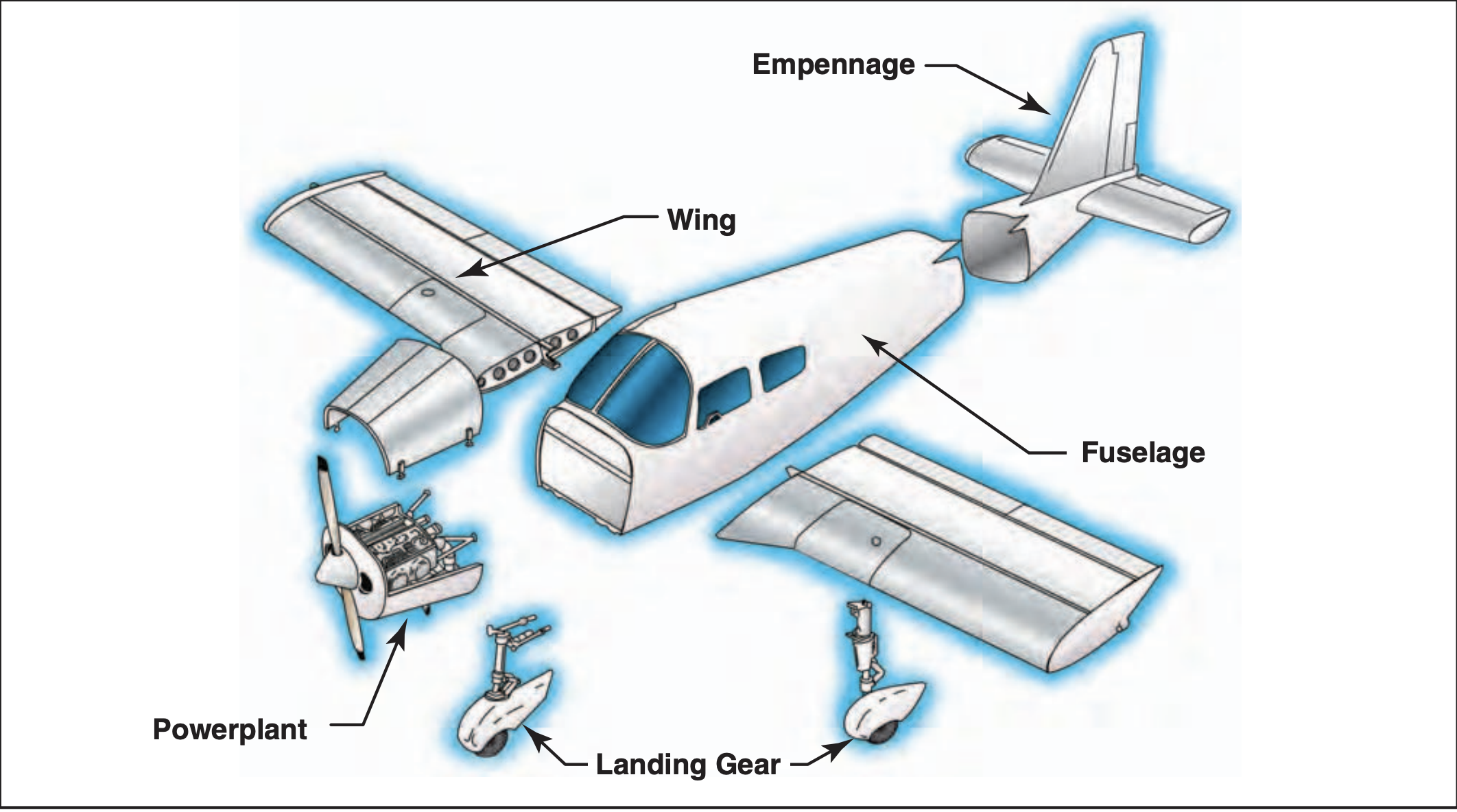
Fuselage
- The fuselage is the central body of an airplane, designed to accommodate the crew, passengers, and cargo.
- The types of fuselage structures in today's aircraft are:
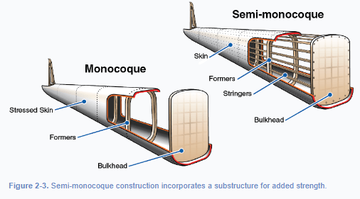
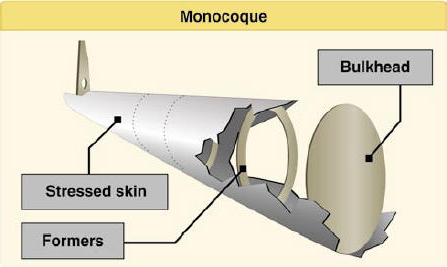
Monocoque

-
Outer Skin Bears the Load: A monocoque fuselage uses its external shell to handle structural stresses, eliminating the need for an internal frame.
-
Lightweight and Aerodynamic: This design reduces weight and drag, making it efficient for aircraft performance.
-
Like a Coca-Cola Can: Just as a Coke can holds pressure with only its curved metal shell, a monocoque fuselage gets its strength from its shape and skin.
-
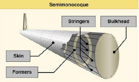
Reinforced Design: A semi-monocoque fuselage combines a load-bearing outer skin with internal structures like frames and stringers for added strength.
-
Efficient and Durable: This design offers a great balance of light weight, structural integrity, and ease of maintenance.
-
Used in the Cessna 172: The popular Cessna 172 features a semi-monocoque airframe, making it both sturdy and reliable for training and general aviation.
Semi-monocoque
While the skin and internal supports form the main structure of the fuselage, another critical component is the firewall.
Located at the front of the fuselage, the firewall is a heat-resistant barrier that separates the engine compartment from the cockpit. It not only protects the occupants from heat and fire but also serves as a structural base for mounting the engine.
The Wing
- Wings are airfoils, they are attached to each side of the fuselage.
- Wings are the main lifting surfaces that support the airplane in flight.
- Wings may be attached at the top, middle or lower portion of the fuselage.
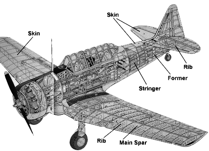
The principal structure parts of the wing are:
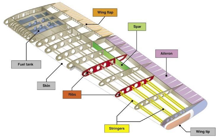
The control surfaces on a wing are ailerons and flaps.
- Spar
- Ribs
- Stringers
Ailerons
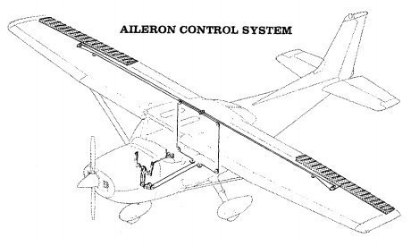
- Extend from about the midpoint of each wing.
- Create aerodynamic force to cause the turn.
Connected by:
- Cables
- Pulleys and/or push-pull tubes
Flaps
- High lifting devices used on an aircraft.
- Attached to the trailing edge of the wing.
Increase both lift and induced drag for any given AOA.
- Cessna 172 has a single slotted type of flaps
- Electrically operated (motor in the right wing)
- Takes 9 seconds to extend and 7 seconds to retract
The Empennage
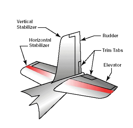
Empennage consists of:
1. Vertical stabilizer/rudder
2. Horizontal stabilizer/ elevator
- Moves the airplane nose left or right (controls yaw)
- Connected by cables & pulleys
- Used to move the nose up or down
- Connected by cables, pulleys, and push-pull tubes
Stabilator
-
A combined stabilizer and elevator at the tail of an aircraft.
-
A one-piece horizontal stabilizer that pivots from a central hinge point.
Trim Tabs
Small surfaces connected to the trailing edge of a larger control surface on an aircraft allowing relief of pressure on the flight controls.
-
On the Cessna 172, the trim is controlled by a trim wheel connected by cable and pulleys.
- When the trim wheel is rotated or moved forward, the nose is held down; conversely, if the trim control is moved back, the nose is held up.
Landing Gear
- Supports the aircraft on the ground.
-
Consist of 3 wheels
- Two main wheels and the third either at the front or rear of the aircraft
Conventional/Tailwheel Landing Gear
Tricycle/Nosewheel Landing Gear
Types of Landing Gear
Fixed
Landing Gear
Retractable
Landing Gear
-
Tricycle type
Cessna 172 Landing Gear
-
Steerable nose wheel
-
Two main wheels
-
Shock absorption is provided by the tubular spring steel main landing gear struts
-
Air/oil nose gear shock strut
Brake System
The Cessna 172 has a single disc, hydraulically-actuated brake on each main landing gear wheel
Each brake is connected to a master cylinder attached to pilot’s rudder pedals
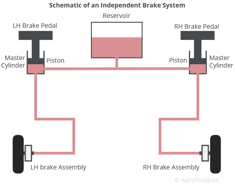
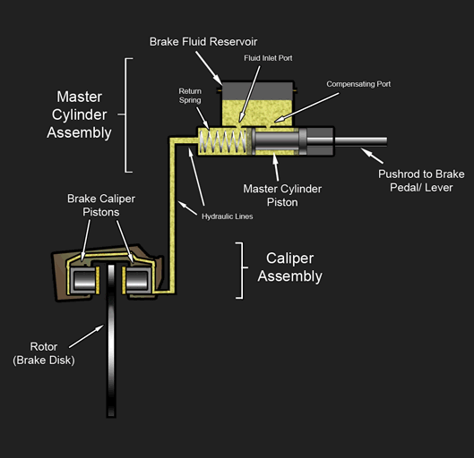
The brakes are operated by applying pressure to the top of the rudder, which is interconnected.
Applying different pressure on each break is known as differential braking.
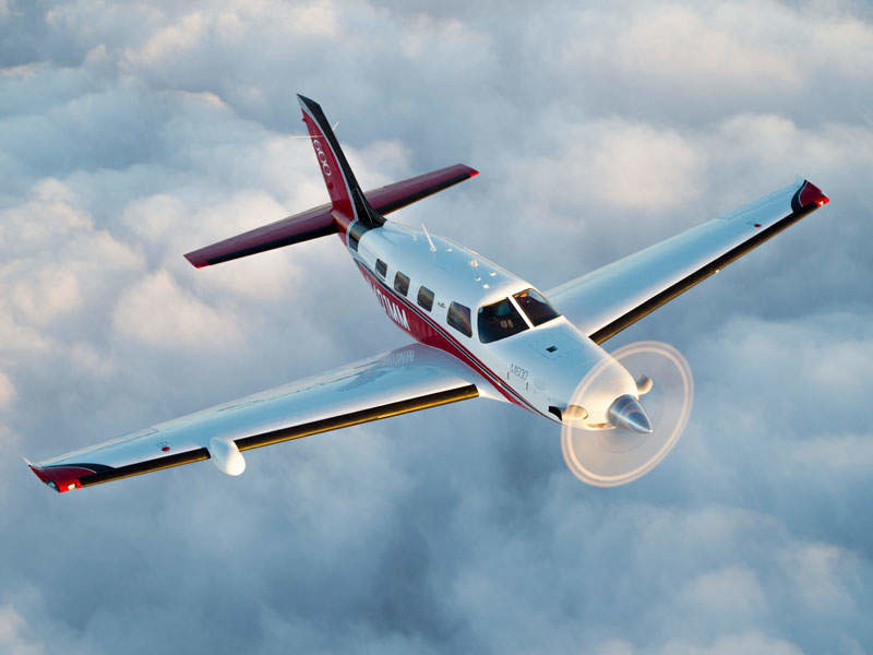
Powerplant
The powerplant includes the engine and propeller, which together generate thrust to move the airplane forward.
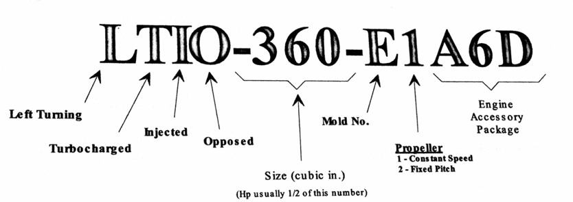
In the Cessna 172M, you'll find a Lycoming O-320, and in the 172SP, a Lycoming IO-360
Cessna 172M Engine
4 Four Cylinders
H Horizontally Opposed
A Air Cooled
N Normally Aspirated
D Direct Drive
L Lycoming O-320-E2D
E Engine Speed - 150HP at 2700RPM
W Wet Sump Oil System
C Carburetor Equipped
Cessna 172SP Engine
4 Four Cylinders
H Horizontally Opposed
A Air Cooled
N Normally Aspirated
D Direct Drive
L Lycoming IO-360-L2A
E Engine Speed - 180HP at 2700RPM
W Wet Sump Oil System
F Fuel Injected
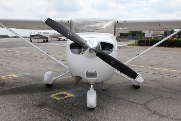
Propeller
The propeller is part of the powerplant and creates thrust by pulling air backward as it spins, much like a rotating wing.
Types
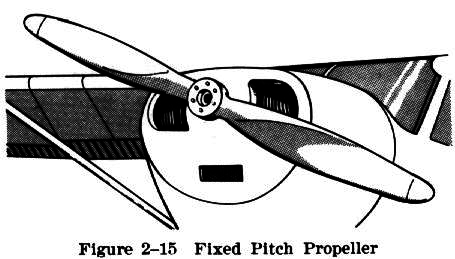
Fixed Pitch Propeller
Constant Speed Propeller
-
Each blade acts like an airfoil, generating lift (thrust) as it cuts through the air.
-
The blades are twisted, with a steeper angle near the center and flatter toward the tip for efficient thrust.
-
The Cessna 172 uses a fixed-pitch propeller, optimized for general performance.
-
The propeller is 75 inches maximum and 74 inches minimum in diameter.
Aircraft Construction Materials
- Most airplanes use metal materials, such as titanium, steel, and aluminum.
- Old designs were made of wood and fabric, while contemporary aircraft engineers prefer composite materials for their durability and environmental benefits.
Metal Construction
Composite Construction
Made of titanium, steel,
and aluminium:
-
Strong
-
More durable
-
Lighter
-
More efficient
-
Easy to manufacture
-
Weather-resistant
Merges two or more materials, such as carbon fiber, Kevlar, and fiberglass:
-
Anticorrosion
-
Longer Lifespan
-
Less Maintenance
-
Smoother Skin
-
Lighter Weight
-
Less Drag
Airworthiness Requirements
Complete a checklist for a preflight inspection to confirm that your airplane is safe before each flight.
- Damages
- Tires
- Fuel
- Oil
- Airworthiness standards
Required Documents
Pilot Operating Handbook
- Contains standardized essential information about specific airplane makes and models.
- The FAA mandates that all newly manufactured airplanes include an FAA-approved (AFM) tailored to each individual aircraft, which must be available to the pilot during flight.
- For many aircraft, the POH serves as the AFM, fulfilling this regulatory requirement.
How do I know my aircraft is safe ?
Airworthiness directives
VOR (30 Days)
Altimeter and Static Pressure System ( 24 calendar months )
Transponder ( 24 calendar months )
Inspection Annual inspection (A&P with IA)100 hours inspection (A&P)
ELT (12 calendar months ) and change the battery when 1 hour accumulated use or 50% of battery life
A
V
I
A
T
E
Airworthiness Directives
- The FAA issues an airworthiness directive (AD), when an unsafe condition could arise or is identified in an aircraft due to a design flaw, maintenance issues, or other factors.
- ADs are mandatory.
Types of ADs
- Notice of Proposed Rulemaking (NPRM), followed by a Final Rule
-
Emergency ADs
Aicraft Equipment Required for VFR
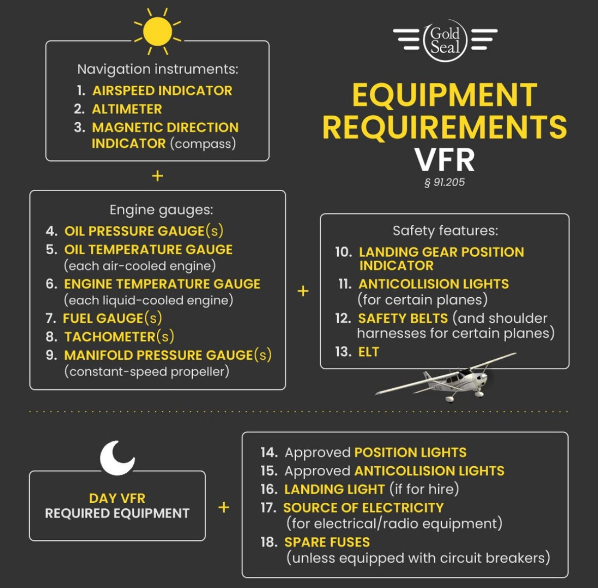
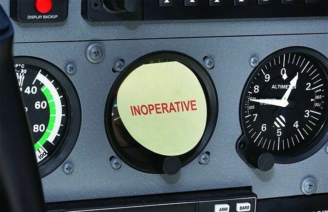
Inoperative Instruments and Equipment
FAA guidelines for operating an aircraft with specific non-essential innoperative equipment.
Minimum Equipment list (MEL)
- Takes into consideration the regulations and specific requirements to indicate the equipment that is allowed to be inoperative for a particular flight operation.
Not on MEL
- Use the procedure described in FAR 91.213 and, if available, the KOEL
Special Flight Permit
- If airworthiness requirements are not met, the FAA can issue a special flight permit (ferry permit) to fly the airplane to a repair location.
-
To obtain the ferry permit, an application must be submitted to the nearest FAA flight standards district office (FSDO).
-
If an AD prohibits further flight until compliance is met, the FSDO may deny the ferry permit and an AMT may have to be moved to the aircraft location and solve the AD first.
Powerplant and Related System
Reciprocating Engine Operation
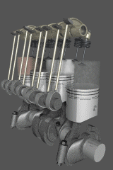
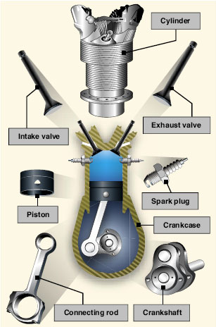
- Reciprocating engines operate on the basic principle of converting chemical energy (fuel) into mechanical energy.
- This conversion occurs within the cylinders of the engine through the process of combustion.
The Four Stroke Process
Review
Video by: Yash Verma
Induction Systems
- The induction system brings in air from the outside, mixes it with fuel, and delivers the fuel-air mixture to the cylinder where combustion occurs.
The throttle controls engine speed by regulating the amount of fuel and air mixture that flows into the cylinder.
The mixture controls the fuel/air ratio.
- Outside air enters the induction system through an intake port on the front of the engine cowling.
- This port normally contains an air filter that inhibits the entry of dust and other foreign objects.
Two types of induction systems are commonly used in small aircraft engines:
Carburetor
Fuel Injection
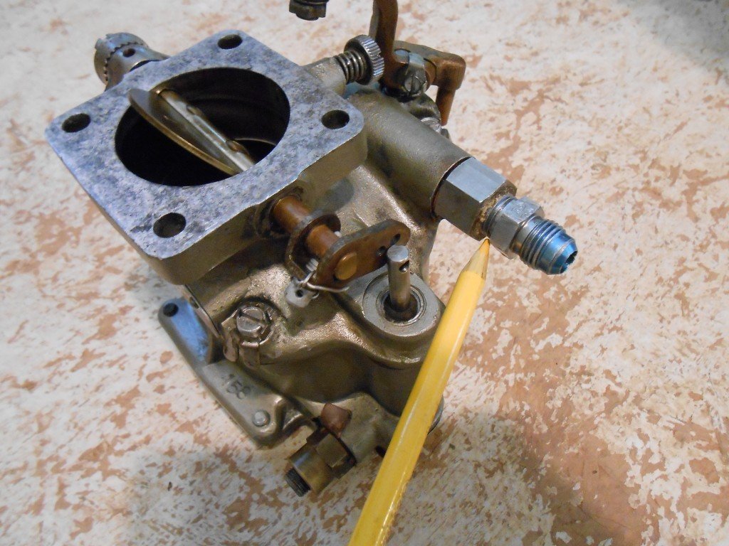
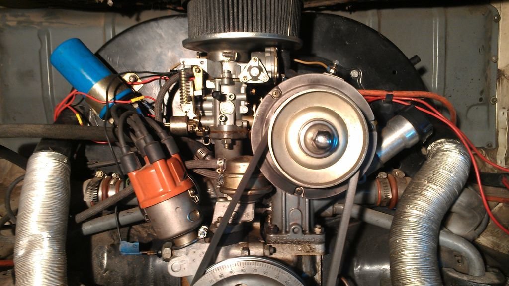
Carburetor
- Fuel and air is combined in the carburetor before this mixture enters the intake manifold.
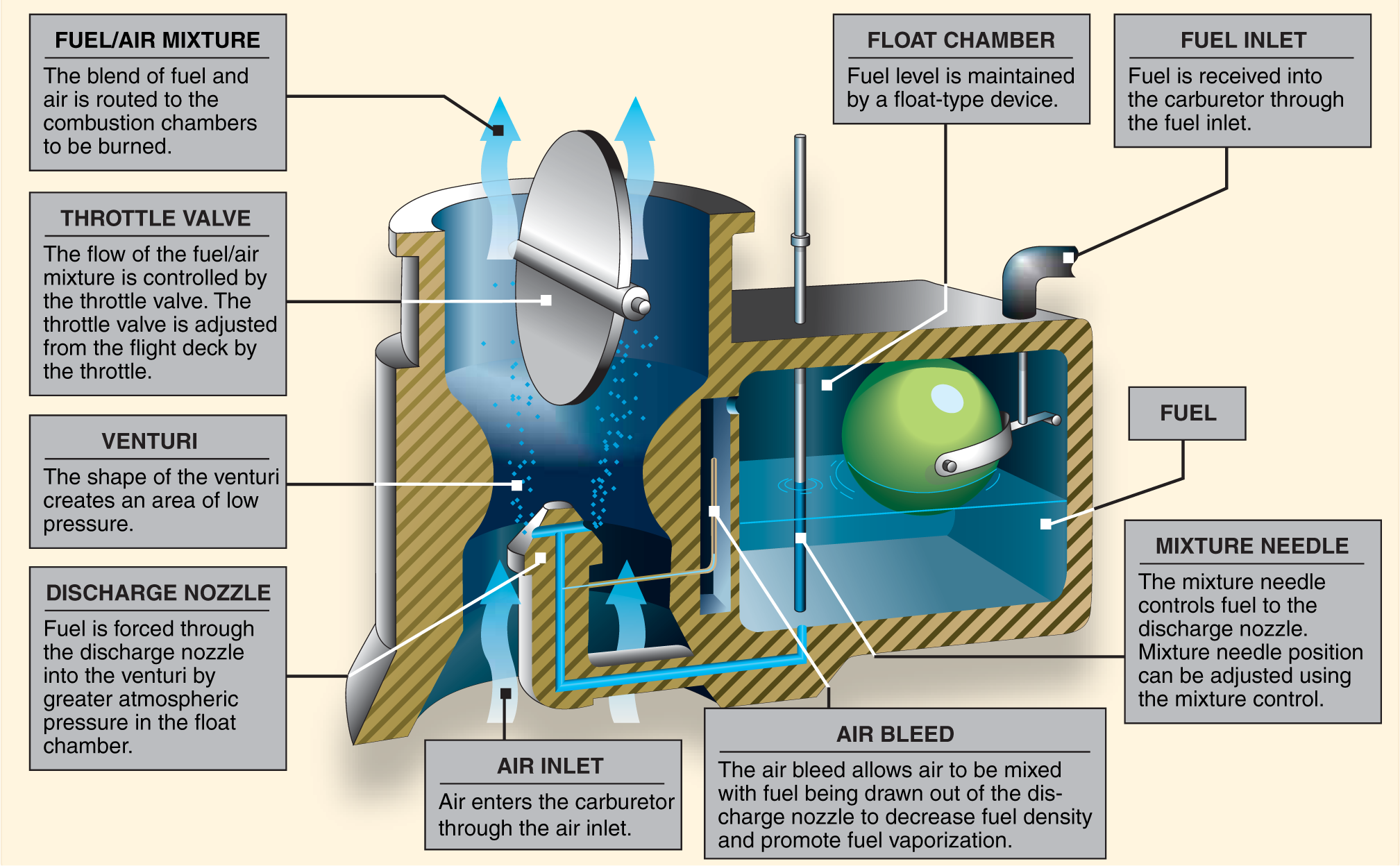
- The Cessna 172M is equipped with a float-type carburetor; outside air first flows through an air filter, usually located at an air intake in the front part of the engine cowling. This filtered air flows into the carburetor and through a venturi, a narrow throat in the carburetor.
- When the air flows through the venturi, a low-pressure area is created, and then the fuel flows into the airstream, where it is mixed with the flowing air.
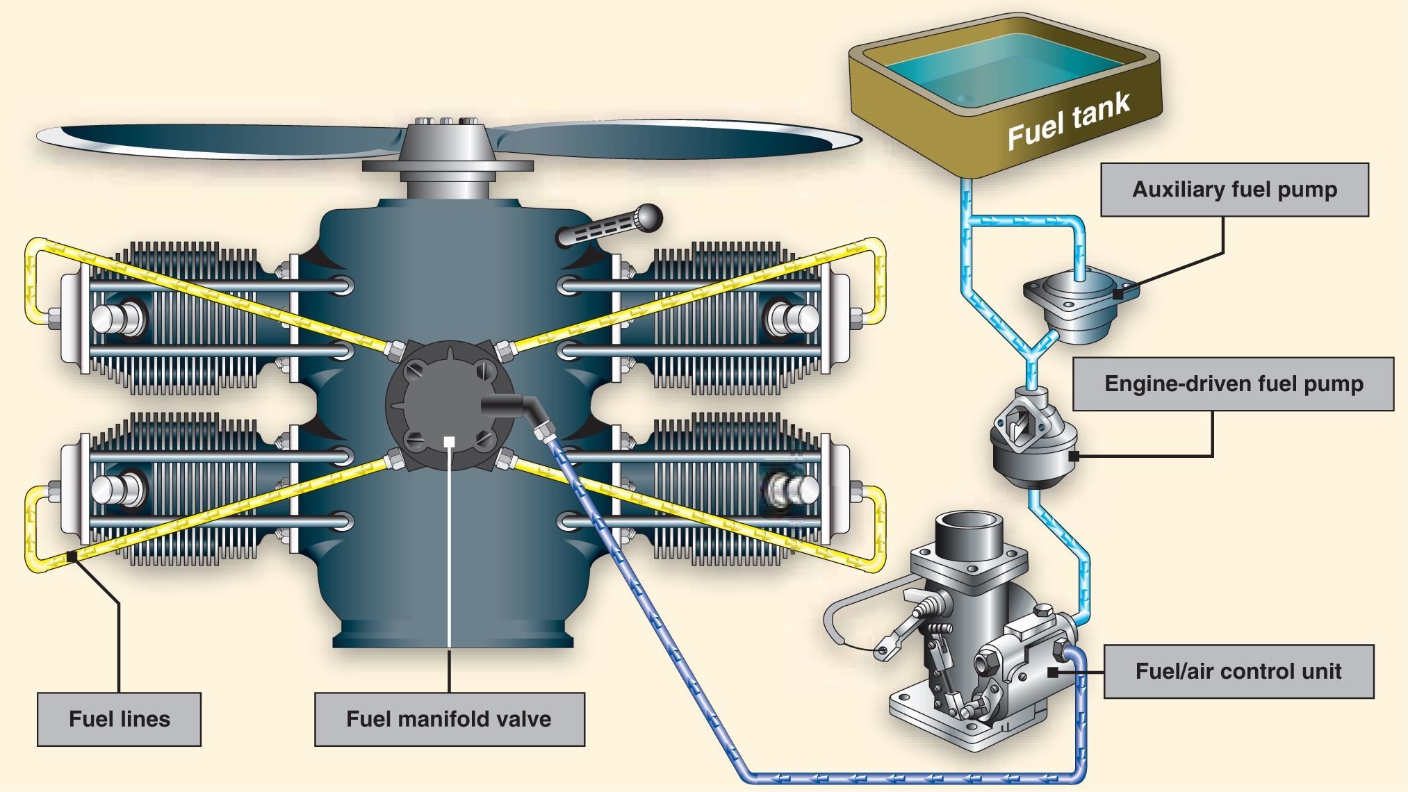
Fuel Injection
-
The fuel injection system mixes the fuel and air immediately before entry into each cylinder or injects fuel directly into each cylinder.
- In a fuel injection system, the fuel is injected directly into the cylinders or just ahead of the intake valve.
- The air intake for the fuel injection system is similar to that used in a carburetor system, with an alternate air source located within the engine cowling.
- This source is used if the external air source is obstructed.
A Fuel Injection System Incorporates 6 Basic Components
-
Engine-driven fuel pump
-
Fuel-air control unit
-
Fuel manifold (fuel distributor)
-
Discharge nozzles
-
Auxiliary fuel pump
-
Fuel pressure/flow indicators.
-
The auxiliary fuel pump provides fuel under pressure to the fuel-air control unit for engine starting and/or emergency use.
-
After starting, the engine-driven fuel pump provides fuel under pressure from the fuel tank to the fuel-air control unit.
-
This control unit, which essentially replaces the carburetor, meters fuel based on the mixture control setting and sends it to the fuel manifold valve at a rate controlled by the throttle.
How does it work?
-
After reaching the fuel manifold valve, the fuel is distributed to the individual fuel discharge nozzles.
-
The discharge nozzles, which are located in each cylinder head, inject the fuel-air mixture directly into each cylinder intake port.
Fuel Manifold Valve
- Less susceptible to icing than the carburetor system.
- Better fuel flow.
-
Precise control of the mixture.
-
Better fuel distribution.
-
Vapor locks during ground operations on hot days.
-
Difficulty in starting a hot engine.
Supercharging and Turbocharging
- To increase an engine’s horsepower, manufacturers have developed forced induction systems called superchargers and turbochargers.
- They both compress the intake air to increase its density.
- The key difference lies in the power supply.
- A supercharger relies on an engine-driven air pump or compressor, while a turbocharger gets its power from the exhaust stream that runs through a turbine, which in turn spins the compressor.
The Ignition System
Provides spark that ignites the fuel/air mixture in the cylinders. Consists of:
-
Dual magnetos
-
Wires, spark plugs
-
Ignition switch
The Magnetos
- A magneto uses a permanent magnet to generate an electrical current completely independent of the aircraft’s electrical system.
- The magneto generates sufficiently high voltage to jump a spark across the spark plug gap in each cylinder.
-
The Cessna 172 incorporates a dual ignition system with two independent magnetos.
-
Each magneto operates independently to fire one of the two spark plugs in each cylinder. The firing of two spark plugs improves combustion of the fuel-air mixture and results in a slightly higher power output. If one of the magnetos fails, the other is unaffected.
-
A malfunctioning ignition system can be identified during the before-takeoff check by observing the decrease in RPM that occurs when the ignition switch is first moved from BOTH to RIGHT and then from BOTH to LEFT.
-
A small decrease in engine RPM is normal during this check. The permissible decrease is listed in the AFM or POH.
-
The ignition system starts working when the crankshaft is moving.
-
A dual ignition system increases safety and improves the performance of the aircraft. So, in case of a failure of one magneto, you have the other.
Abnormal Combustion
Detonation
Detonation is an uncontrolled, explosive ignition of the fuel-air mixture within the cylinder’s combustion chamber.
Causes:
- Use of a lower fuel grade than that specified by the aircraft manufacturer.
- Operation of the engine with extremely high manifold pressure in conjunction with low RPM.
- Operation of the engine at high power settings with
an excessively lean mixture. - Maintaining extended ground operations or steep climbs in which cylinder cooling is reduced.
Pre-Ignition
Pre-ignition occurs when the fuel-air mixture ignites before the engine’s regular ignition event.
Causes
- Carbon deposits form around spark plugs due to improper mixture leaning during taxing or flight.
- Cracked spark plugs insulators.
- Damage in the cylinder that causes a part to heat sufficiently to ignite the fuel-air charge.
Fuel System
The fuel system is designed to provide an uninterrupted flow of clean fuel from the fuel tanks to the engine.
Two common classifications apply to fuel systems in small aircraft: Gravity-feed and Fuel-pump systems
- The gravity-feed system utilizes the force of gravity to transfer fuel from the tanks to the engine. For example, on high-wing airplanes, the fuel tanks are installed in the wings.
- Aircraft with fuel pump systems have two fuel pumps. The main pump system is engine-driven, with an electrically-driven auxiliary pump provided for use during engine starting and in the event the engine pump fails.
Cessna 172M Fuel System
A total of 42 gallons, but only 38 gals usable.
Cessna 172 SP Fuel System
Total 56 gallons but only 53 gals are usable.
Refueling
-
Static electricity is formed by the friction of air passing over the surfaces of an aircraft in flight and by the flow of fuel through the hose and nozzle during refueling.
-
A ground wire should be attached to the aircraft before the fuel cap is removed from the tank to prevent igniting the fuel.
-
Don't forget to drain a small amount of fuel from tanks before each flight to check for any contaminants.
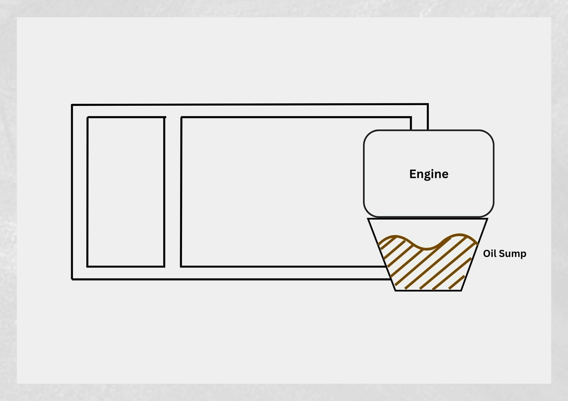
Oil system
The engine oil system performs several important functions:
- Lubrication of the engine’s moving parts
- Cooling of the engine by reducing friction
- Removing heat from the cylinders
- Providing a seal between the cylinder walls and pistons
- Carrying away contaminants
C172SP Oil Sump capacity is 8 quarts, minimum is 5 quarts.
C172M Oil Sump capacity is 8 quarts, minimum is 6 quarts.
- Reciprocating engines use either a wet-sump or a dry-sump oil system. In a wet-sump system, the oil is located in a sump that is an integral part of the engine.
- In a dry-sump system, the oil is contained in a separate tank and circulated through the engine by pumps.
C172M and C172SP are equipped with a wet-sump system.
C172M and C172SP:
- The entire system holds 9 quarts of oil.
- The oil sump contains 8 quarts of oil.
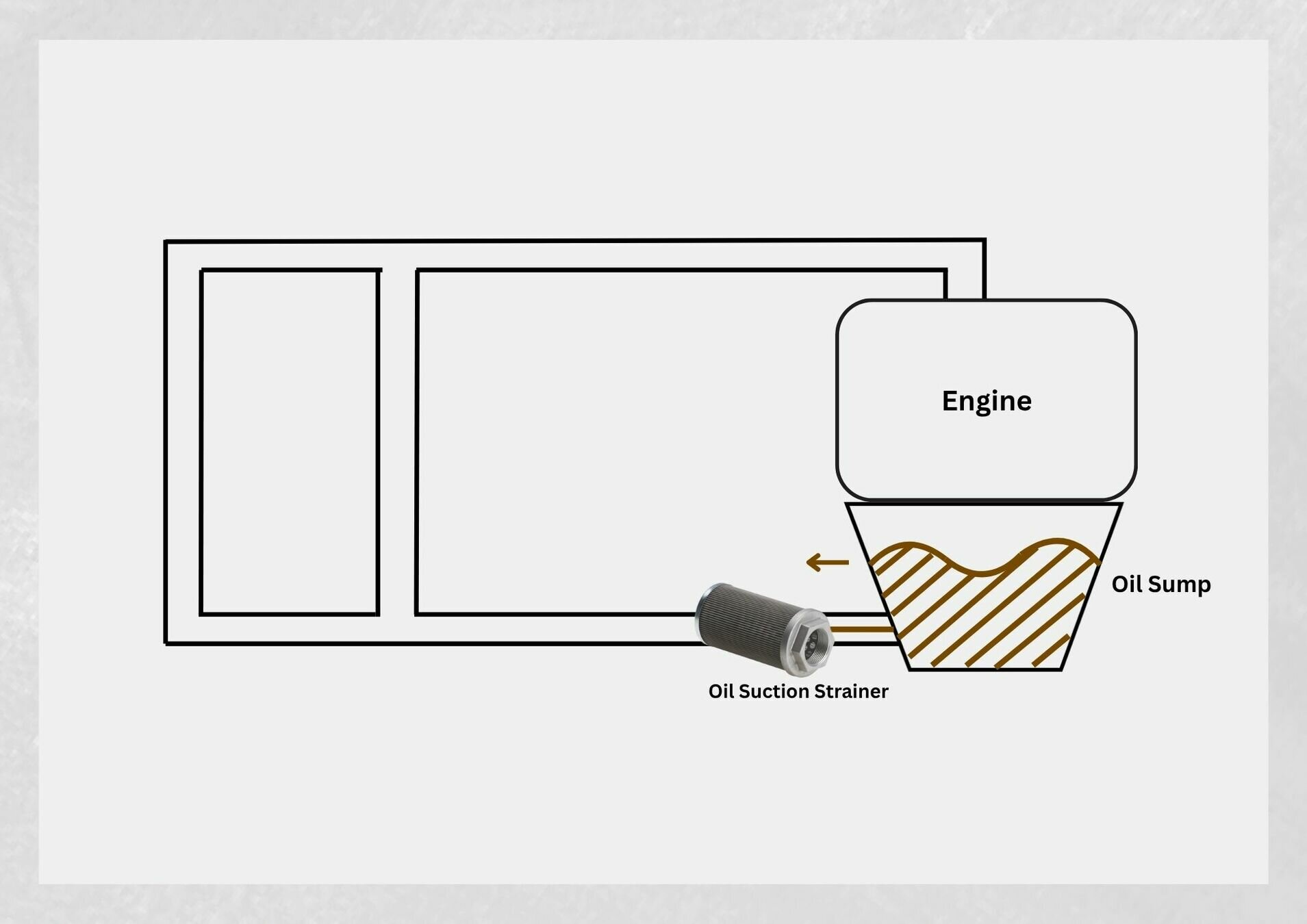
- The oil suction strainer removes and filters out all large contaminants from the oil.
Oil Suction Strainer
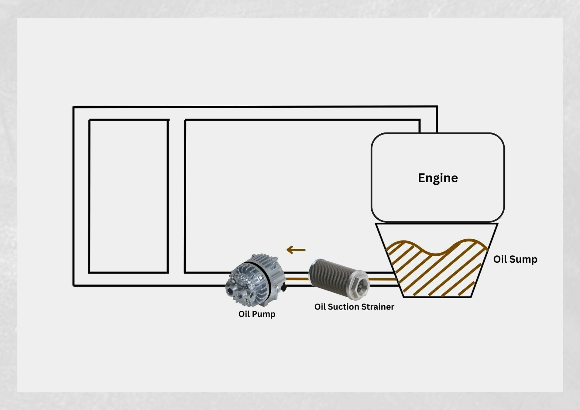
- The oil pump draws the oil and distributes it throughout the system.
Oil Pump
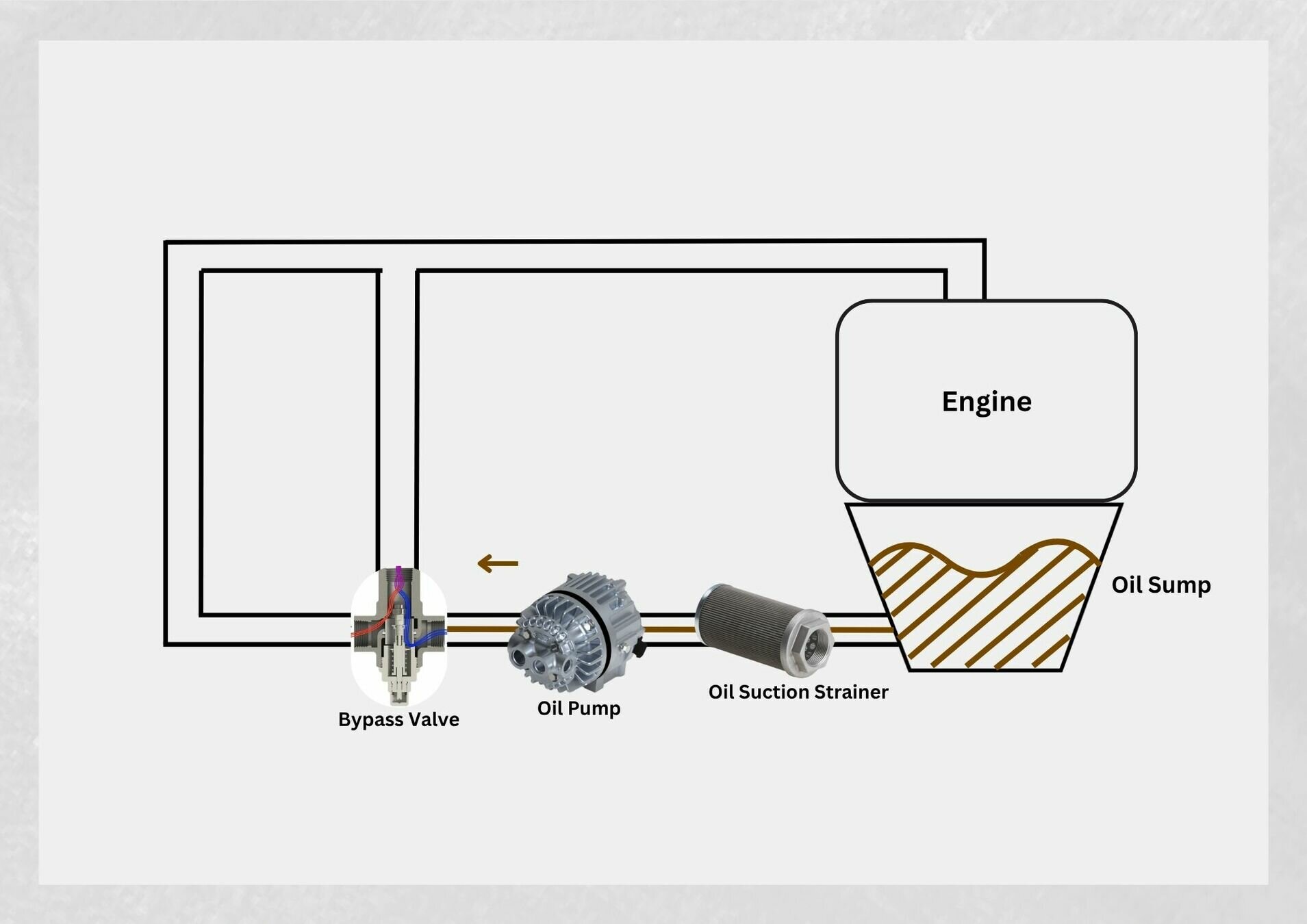
- When the oil reaches high temperatures, it is bypassed to the oil cooler via the bypass valve.
Bypass Valve
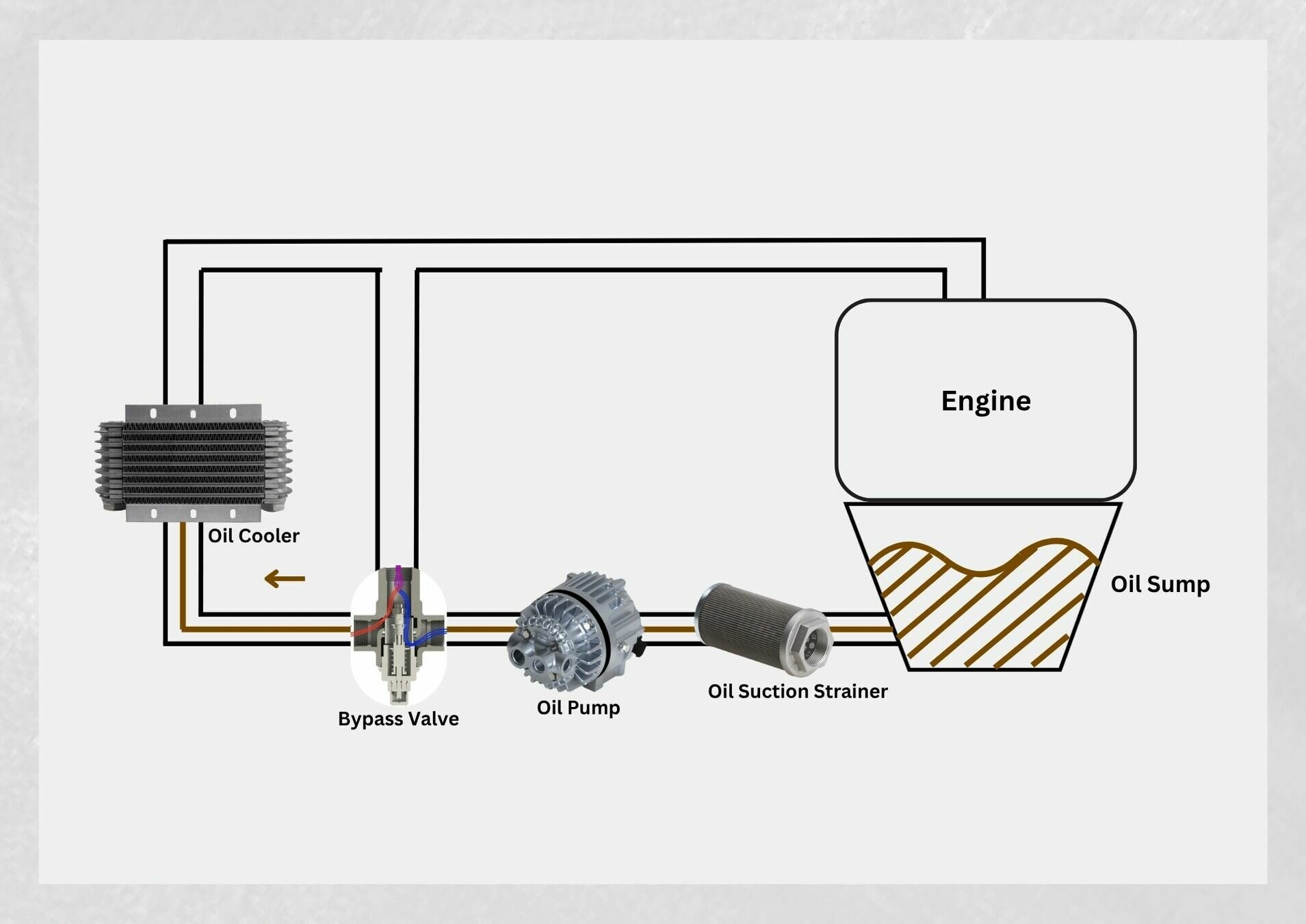
- The oil cooler cools the oil before it goes to the pressure strainer screen.
Oil Cooler (warm oil)
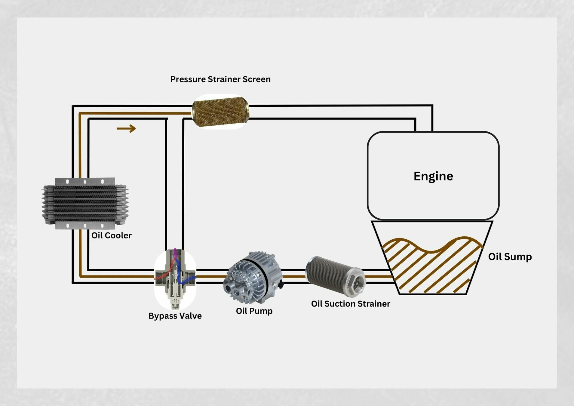
- The oil pressure strainer screen filters out smaller contaminants that may be present in the oil.
Pressure Strainer Screen
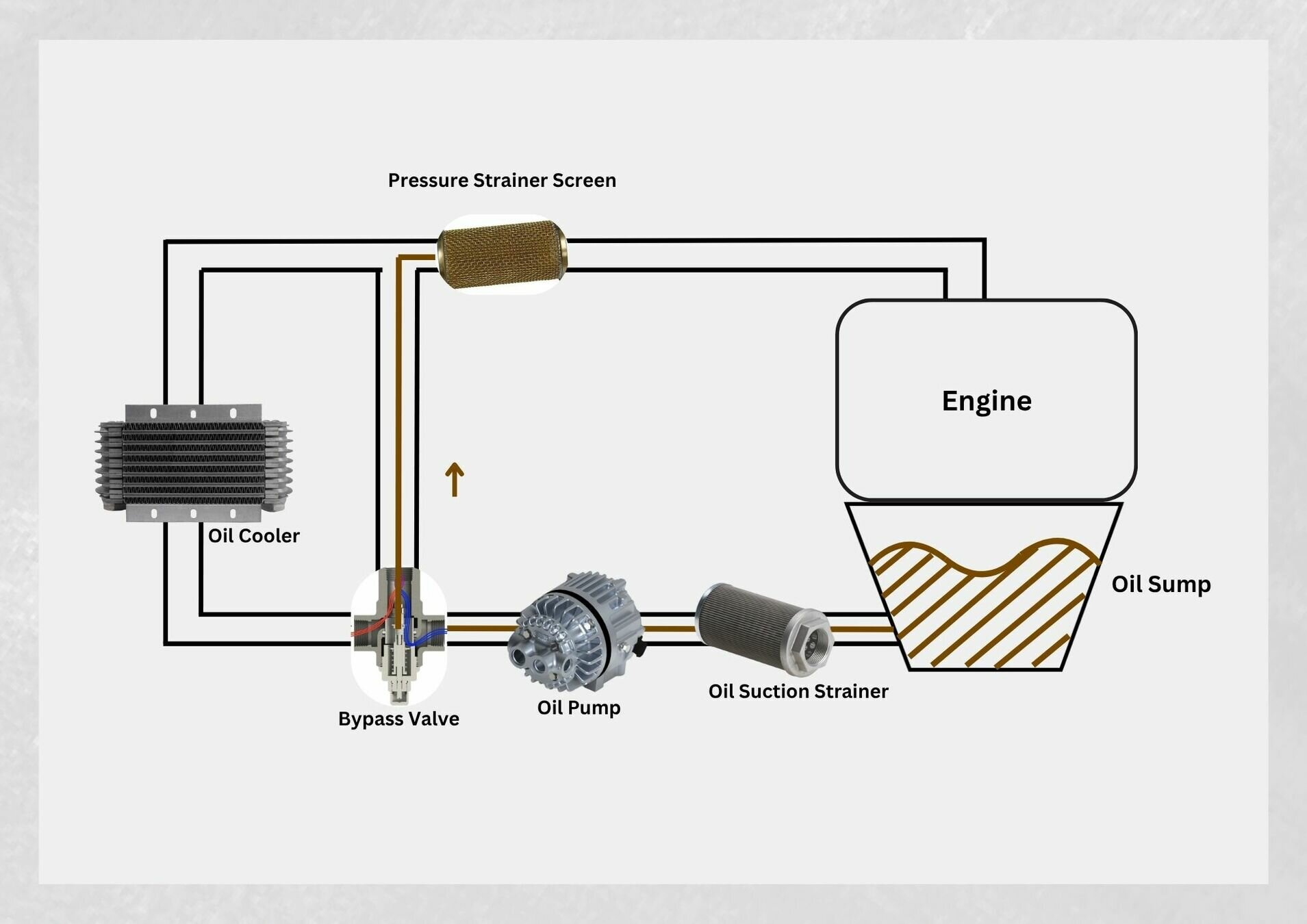
- When the oil temperature is sufficiently cool, it is directed straight to the pressure strainer screen thanks to the bypass valve.
Bypass Valve (cold oil)
- The pressure relief valve regulates engine oil pressure by allowing excess oil to return to the sump.
Pressure Relief Valve
- The oil cleans, cools, lubricates, and seals the various engine parts. Residual oil is returned to the sump by gravity.
Oil Purpose
- For more information refer to the C172M and C172 SP POH section 7
Cooling Systems
- Air cooling is accomplished by air flowing into the engine compartment through openings in front of the engine cowling.
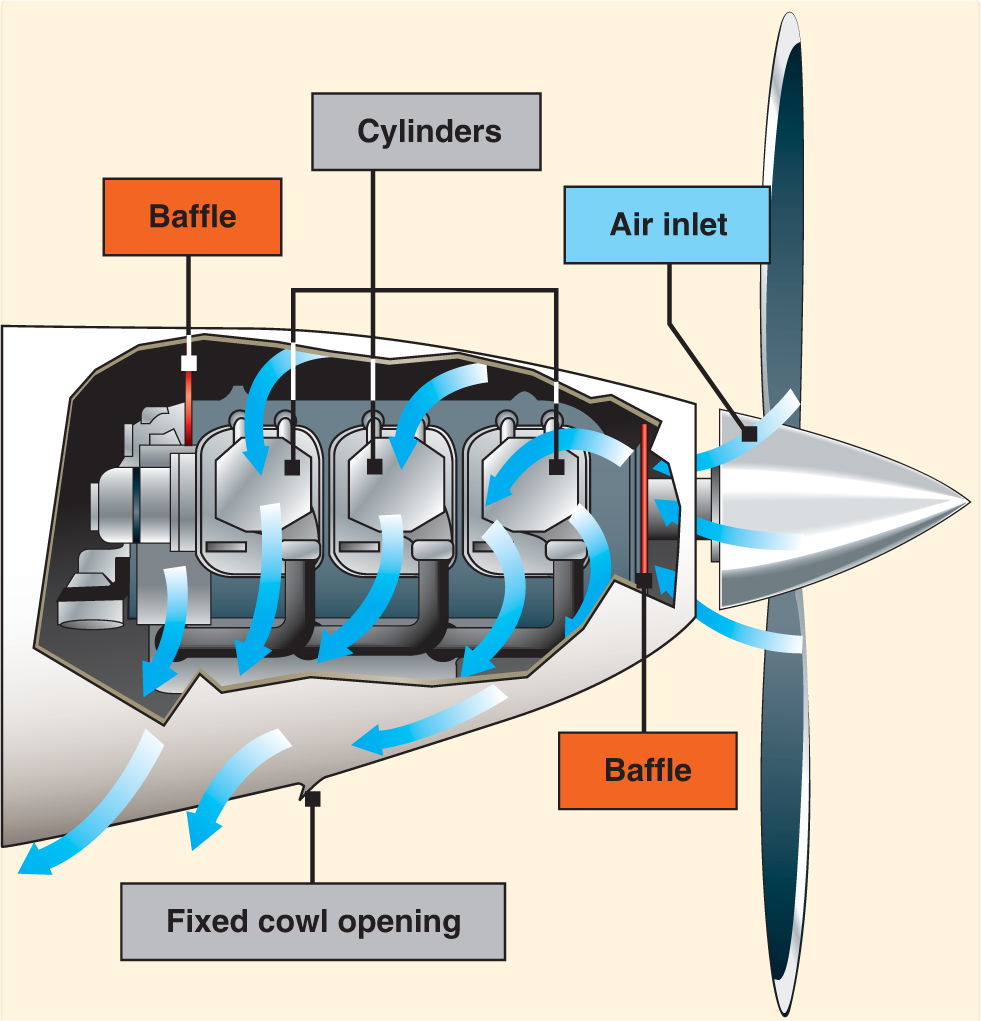
- The outside air enters the engine compartment through an inlet behind the propeller hub. Baffles direct it to the hottest parts of the engine, primarily the cylinders.
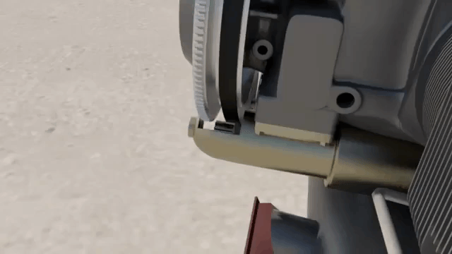
The Exhaust System
Engine exhaust systems vent the burned combustion gases overboard, provide heat for the cabin, and defrost the windscreen.
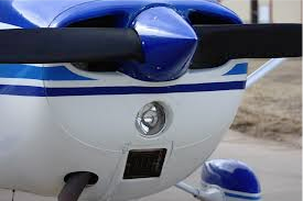
Propeller
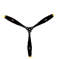
- Mounted on the front of the engine.
- Translates the rotating force of the engine into thrust.
Types
Fixed-Fitch
Propeller
Constant-Speed Propeller
Fixed Pitch Propeller
This type of propeller does not require any control inputs from the pilot in flight.
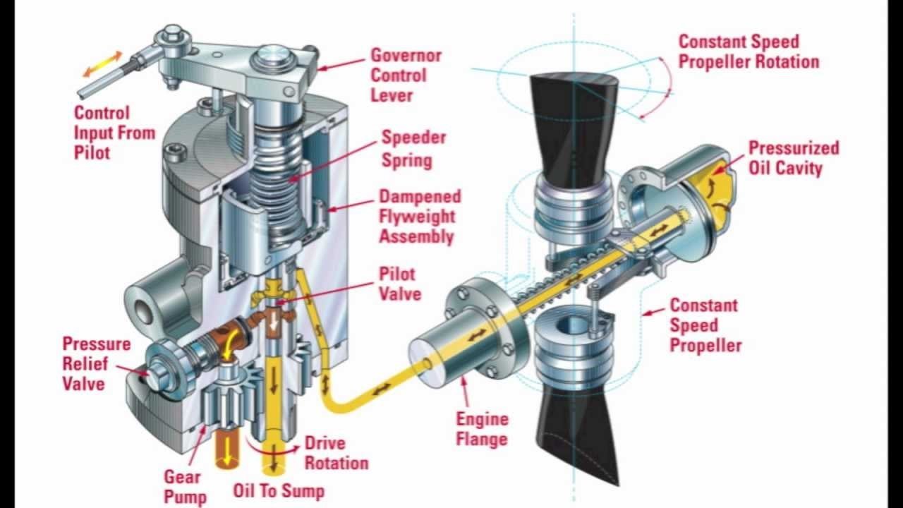
Constant-Speed Propeller
A constant-speed propeller needs input from the pilot to change its blade pitch to allow it to maintain a constant RPM setting.
-
The Cessna 172 has a 2-bladed, fixed-pitch propeller.
-
The propeller has a maximum diameter of 75 inches and a minimum diameter of 74 inches.
Propeller Hazards
Prior to starting an engine, The PIC is responsible the clear the area.
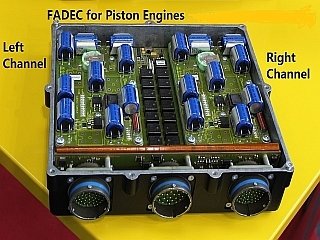
Full Authority Digital Engine Control
FADEC
-
Full Authority Digital Engine Control (FADEC) means just that. There is no direct pilot control over the engine or manual control mode. If the FADEC fails, the engine fails. However, system redundancy makes it much less likely for a FADEC system to fail than a traditional magneto system. In fact, a double magneto failure is statistically more likely than a FADEC failure.
Electrical System
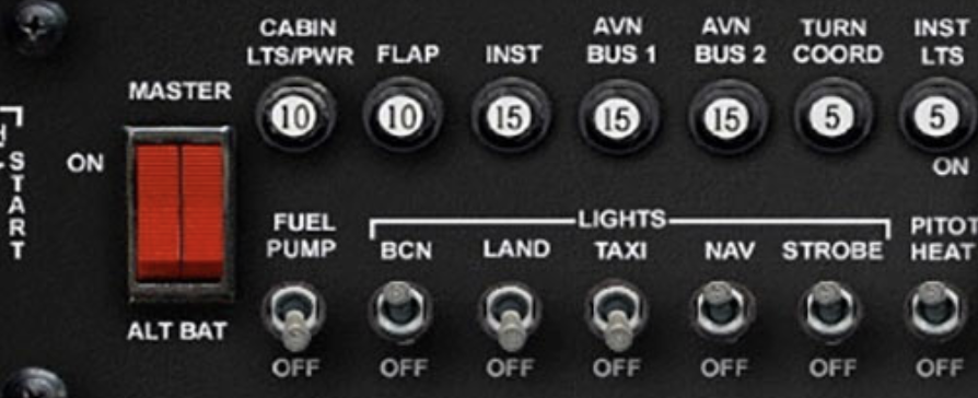
- The primary function of an aircraft electrical system is to generate, regulate, and distribute electrical power throughout the aircraft.
- Most aircraft are equipped with either a 14-volt or a 28-volt direct current (DC) electrical system. A basic aircraft electrical system consists of the following components:
- Master switch
- Battery (12 Volts 25 amp)
- Alternator (14 Volts 60 amp)
- Starter
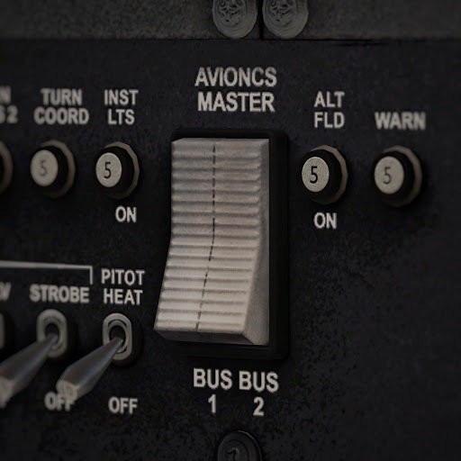
- Buses
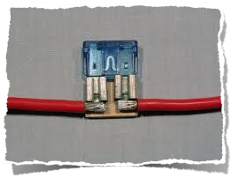
- Circuit Brakers / Fuses
- Voltage Regulator
Master Switch
- The electrical system is turned ON or OFF with a master switch. The C172 has a Split Rocker Type.
- This would be the equivalent of turning your car keys to run electrical components without actually starting the car.
- Turning the master switch to the ON position provides electrical energy to all the electrical equipment circuits except the ignition system.
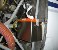
Battery
Starter
Starter
Alternator
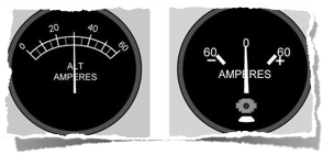
Ammeter vs Loadmeter
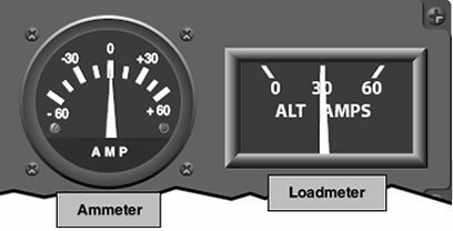
Ammeter
- Ammeters are designed with a negative or positive indication on either side.
- Used to monitor the performance of the electrical system.
- Shows if the alternator/generator is producing adequate electrical power. Also whether or not the battery is receiving electrical charge.
Indications
- Minus indication: More current being drawn from the battery than is being replaced.
- Full scale minus: Malfunction of the alternator/generator.
- Full scale positive: Malfunction of the electrical regulator.
Loadmeter
- Reflects the total percentage of the load placed on the electrical system by accessories and the battery.
- Also reflects the amount of charging current demanded by the battery.
- The Cessna 172 does not use loadmeters.
The buses distribute local high-current power to the different electrical equipment such as:
-
Aircraft lights
-
Avionics (GPS, radios)
Buses
-
Both protect the electrical equipment in case of overload
Circuit Brakers / Fuses
- The avionics Switch allows you to isolate the avionics bus.
-
Turns ON the comms, GPS and navigation equipment.
Avionics Switch
-
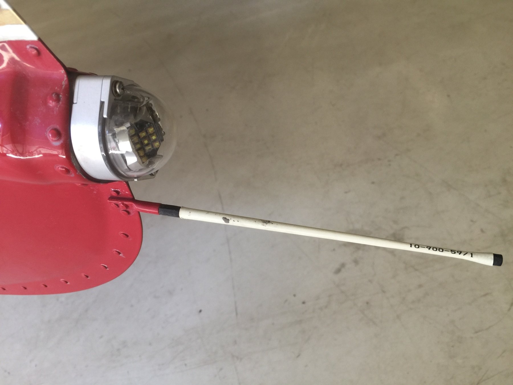
Mitigate buildup of static electricity
-
If missing the pilot might experience interference with communications
Static Wicks
Flight Instruments
Pitot Static Instruments
- The pitot-static system is a combined system that utilizes the static air pressure (static port) and the dynamic pressure (pitot tube) due to the motion of the aircraft through the air.
The pitot tube is utilized to measure the total combined pressures that are present when an aircraft moves through the air. Called dynamic pressure or ram air pressure.
Pitot Tube
Click Here
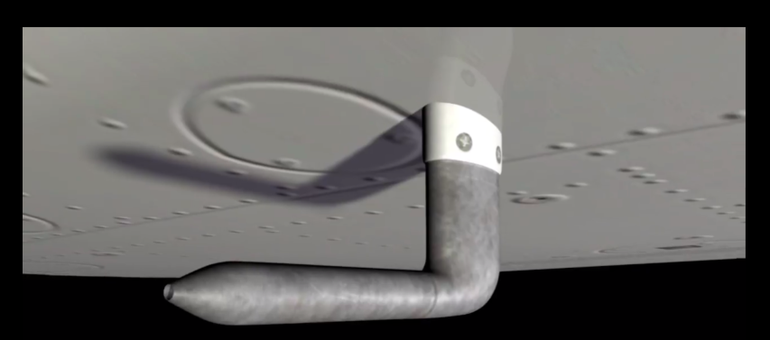
Static Port
Click Here

Measure the static pressure, also known as ambient air pressure, located where there's almost no interference with air surrounding for accuracy.
- These combined pressures are utilized for the operation of the airspeed indicator (ASI), altimeter, and vertical speed indicator (VSI).
Airspeed Indicator
A diaphragm receives ram air coming from the pitot tube, then expands or contracts against the static pressure to display the aircraft's airspeed.
Animation by ERAU
Review
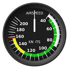
Airspeed Indicator Markings
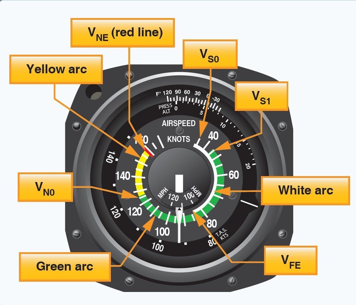
- FAA requires that ASIs are marked in accordance with a standard color-coded marking system. This includes the following standard color-coded markings:
- Lower limit of Green arc V(S1): Stall speed clean configuration.
- Lower Limit of White Arc V(so) = Stall speed landing configuration.
- White arc: The flap operating range since its lower limit represents the full flap stall speed and its upper limit provides the maximum flap speed.
- Green arc: The normal operating range of the aircraft. Most flying occurs within this range.
- Yellow arc: Caution range. Fly within this range only in smooth air and only with caution.
- Red line (VNE): Never exceed speed. Operating above this speed is prohibited, as it may result in damage or structural failure.
Additional V-Speeds
| VX | Best angle climb speed | |
| VY | Best rate climb speed | |
| VA | Maneuvering speed | |
| VFE-10° | Maximum speed - Flaps 10° Flaps extended | |
| VG | Best glide speed |
| VR | Rotation speed |
| VREF | Reference landing approach speed |
Climb Speeds
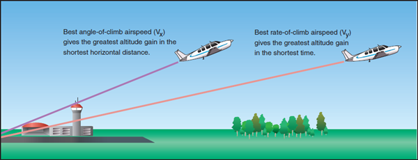
-
Best Angle of Climb (VX):
- It provides the greatest gain in altitude in the shortest distance during climb after takeoff.
-
Best Rate of Climb (VY)
- It provides the greatest gain in altitude over a period of time.
Types Of Airspeeds
Indicated Airspeed
Calibrated Airspeed
Equivalent Airspeed
True Airspeed
Ground Speed
As a pilot you need to become familiar with the different types of airspeed.
Indicated Airspeed
Indicated airspeed (IAS)—the direct airspeed reading obtained from the instrument.
Calibrated Airspeed
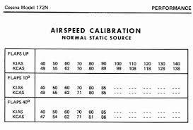
-
Calibrated airspeed (CAS)- is indicated airspeed corrected for instrument installation.
-
Manufacturers attempt to keep airspeed errors to a minimum.
True Airspeed

-
True airspeed (TAS)- calibrated airspeed corrected for altitude and nonstandard temperature.
-
At sea level on a standard day, CAS is equal to TAS.
Ground Speed
-
True airspeed adjusted for wind, actual speed of the airplane over the ground.
-
Ground airspeed decreases with a headwind and increases with a tailwind.
Mach Speed
- Mach is the ratio of the aircraft's true airspeed to the speed of sound.
- Example: .8 Mach = 80% of the speed of sound.
Instrument Check
- When the airplane is not moving airspeed should read 0.
- When taking off, airspeed should move as the airplane accelerates on the runway.
Instrument Error
- Pitot tube blocked
- Ram air blocked
- Static port blocked
- Cold temperature: IAS lower than TAS
- Warm temperature: IAS higher than TAS
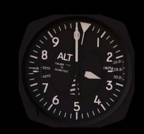
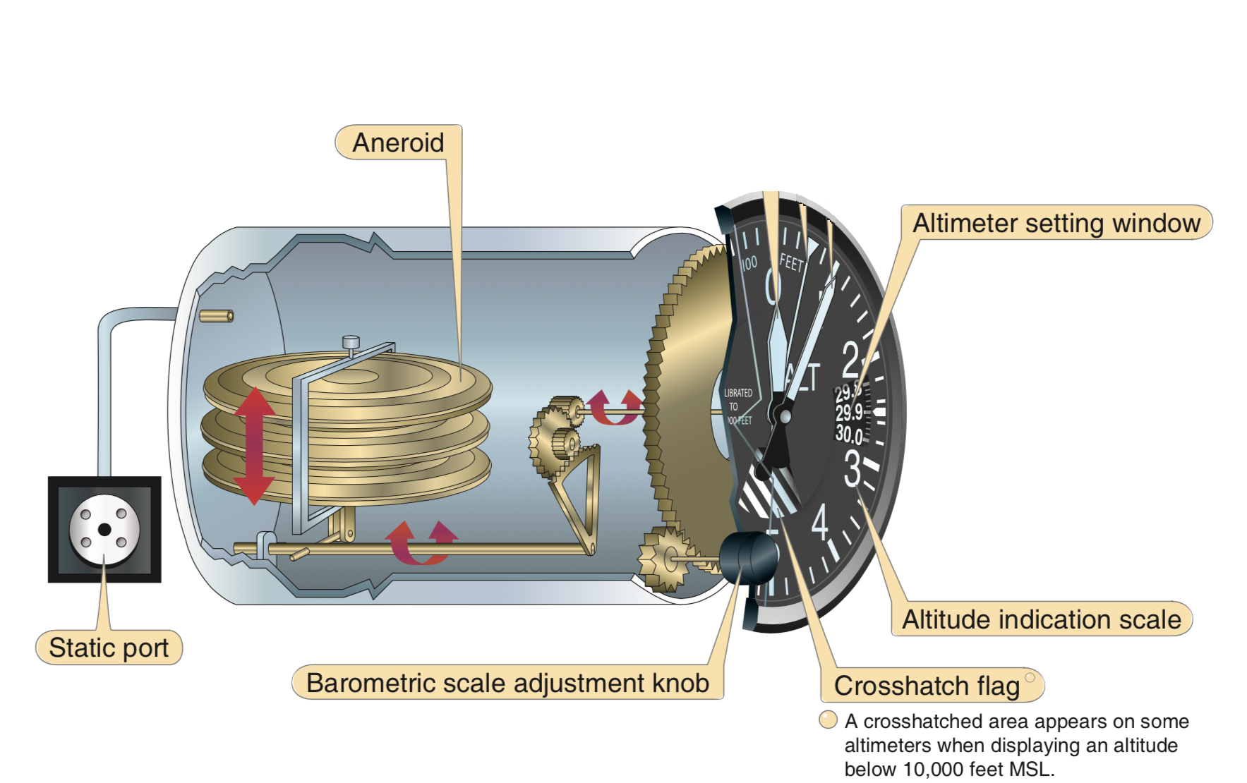
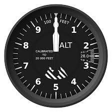
Altimeter
Instrument that measures the height of an aircraft above a given pressure level.
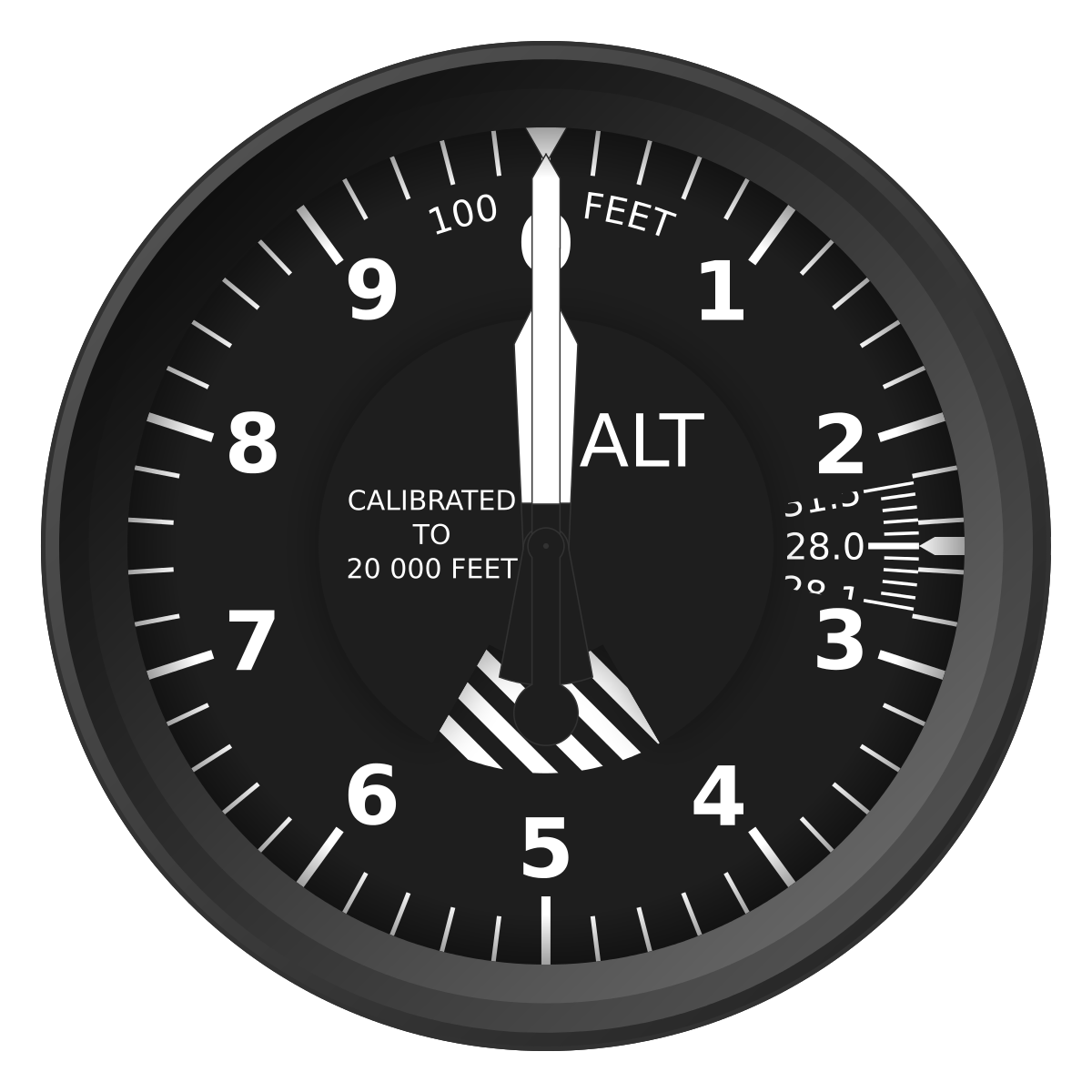
Altimeter has three moving hands
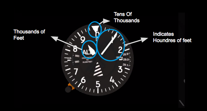
Indicates
Hundreds of feet
Tens of
Thousands
Thousands of Feet
For Example:
ANSWER: 3,000 Feet
What Altitude does is it show?
The altimeter can be adjusted for the current barometric pressure.
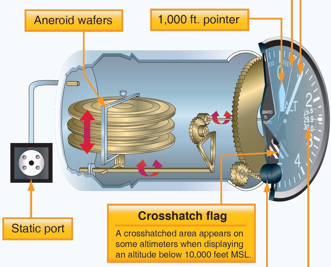
A sealed aneroid wafer, with an internal pressure of 29.92" Hg, is the main component of the altimeter. These wafers are free to expand and contract with changes to the static pressure.
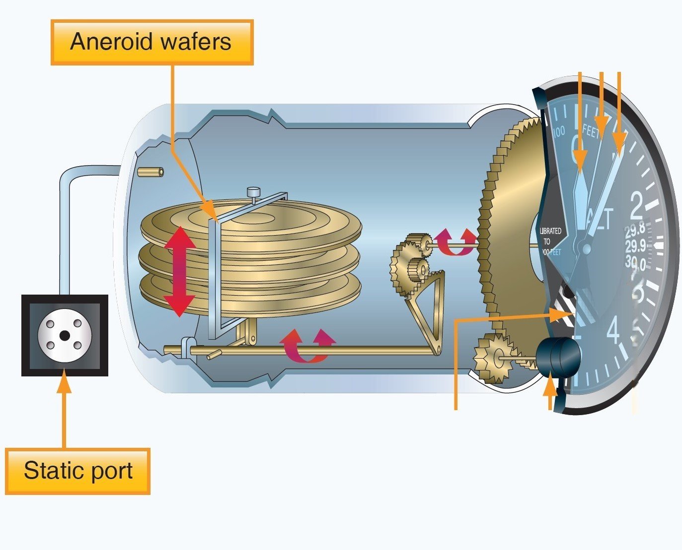
Altimeter Mechanism
What happens when the airplane climbs or descends?
-
A higher static pressure presses down on the wafers and causes them to constrict. A lower static pressure (less than 29.92 "Hg) allows the wafers to expand.
Animation by ERAU
A mechanical linkage connects the wafer movement to the needles, which translates the compression of the wafers into an increase or decrease in altitude.
Types of Altitudes
Indicated Altitude
Pressure Altitude
Absolute Altitude
Density Altitude
True Altitude
Altitude is the vertical distance above some point or level used as a reference. There are as many kinds of altitude as there are reference levels from which altitude is measured, and each may be used for specific reasons.
Indicated Altitude
Altitude read directly from the altimeter (uncorrected) when it is set to the current altimeter setting.
Pressure Altitude
Pressure altitude is the height above a standard datum plane (SDP), which is a theoretical level where the weight of the atmosphere is 29.92" Hg (1,013.2 mb) as measured by a barometer.
Formula: ( Standard Pressure - Current Pressure ) X 1000 +/- Field Elevation
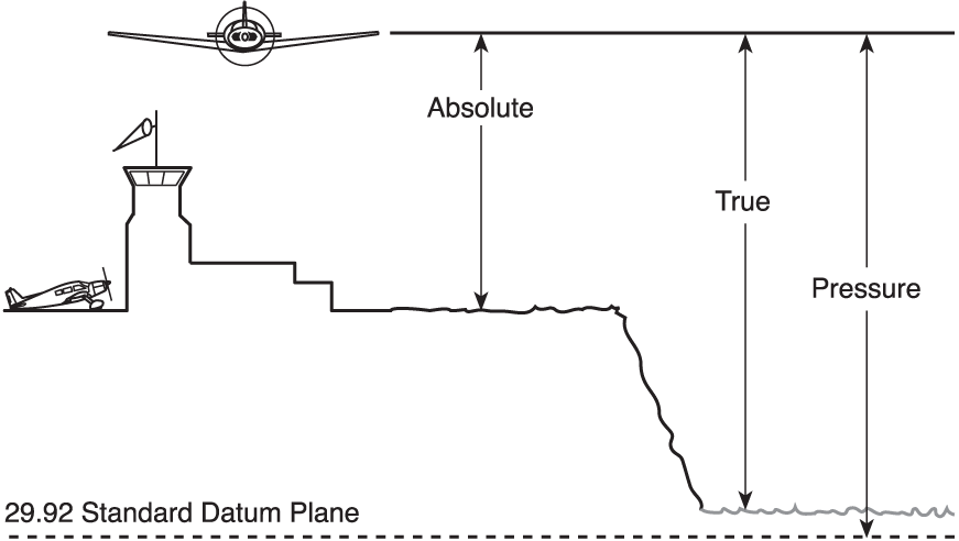
Absolute Altitude
The vertical distance of an aircraft above the terrain, or above ground level (AGL).
Density Altitude
Pressure altitude corrected for variations in standard temperature. When conditions are standard, pressure altitude and density altitude are the same. As the density of the air increases (lower density altitude), aircraft performance increases. Conversely, as air density decreases (higher density altitude), aircraft performance decreases.
In a sense, it's the altitude at which the airplane "feels" it's flying.
-
Formula: Density altitude = Pressure altitude + (OAT-ISA) *120
- Pressure - As pressure increases, with temperature constant, density increases. In other words, the greater the pressure, the more volume of air molecules you have.
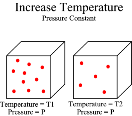
What are the factors that affect density altitude?
-
Temperature - When the air is warmer than standard, it's less dense and performance decreases.

- Humidity - more water vapor in the air, the air has less mass - which means it's less dense.
True Altitude
True altitude is the actual elevation above mean sea level.
Altimeter Check
- When the altimeter setting is set to 29.92'' Hg, it reads pressure altitude.
- When the local altimeter setting is set, there should be no more than 75 feet difference between the altimeter reading and the field elevation
Altimeter Errors
-
Mechanical error:
-
Perform a preflight check to determine the condition of an altimeter by setting the barometric scale to the local altimeter setting. The error should not more than 75 feet.
-
There are two types of errors:
Altimeter Setting:
-
This error occurs when the altimeter is not adjusted to the local altimeter setting to compensate for nonstandard pressure.
-
High to low look out below.
-
Low to high you are in the sky.
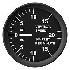
Vertical Speed Indicator
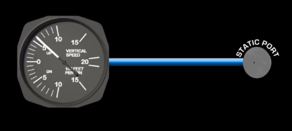
Indicates whether the aircraft is climbing, descending, or in level flight. The rate of climb or descent is indicated in feet per minute (fpm). Uses data from only the static port.
Displays two different types of information:
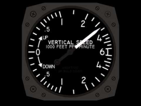
Shows an immediate indication of an increase or decrease in the aircraft’s rate of climb or descent.
Shows a stabilized rate of change in altitude.
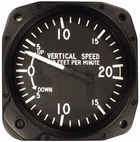
Trend information
Rate information
It contains a diaphragm with a connecting linkage and gearing to the indicator pointer inside a case.
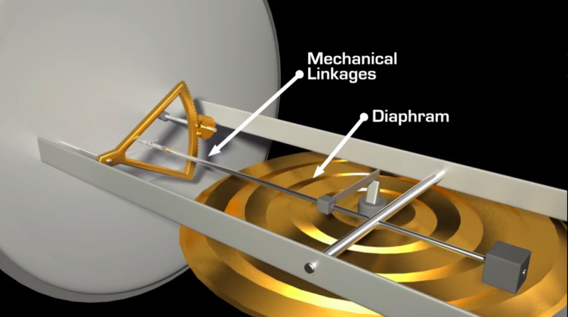

The inside of the diaphragm is connected directly to the static line of the pitot-static system.
Calibrated Leak
The area outside the diaphragm, which is inside the instrument case, is also connected to the static line but through a restricted orifice (calibrated leak).
The difference in timing between these two pressures indicates how fast the airplane is climbing or descending.
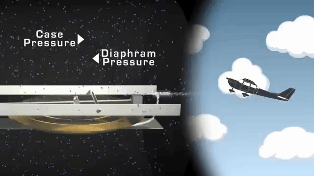
When the aircraft climbs or descends, the pressure inside the diaphragm changes immediately, but due to the calibrated leak, the case pressure remains higher or lower for a short time, causing the diaphragm to contract or expand.
Animation by ERAU
- If the pitch attitude is held constant, the needle stabilizes after a short period (6–9 seconds) and indicates the rate of climb in hundreds of fpm.
- The time period from the initial change in the rate of climb until the VSI displays an accurate indication of the new rate is called the lag.
Instrument Check
Before engine start, the VSI should read 0. If not, use the reading as it is level.
Instrument Error
Sudden or abrupt changes in aircraft attitude cause incorrect instrument readings as the air flow fluctuates over the static ports. Delays from 6-9 seconds.
Pitot System Blockage
Pitot Tube Blockage
-
Airspeed: If the pitot tube is clogged but drain hole is open, indicated airspeed drops slowly to zero because ram air is no longer able to enter the pitot system. Air already in the system vents through the drain hole, and the remaining pressure drops to ambient (outside) air pressure.
-
If the pitot tube ram pressure hole and drain hole become obstructed, the ASI operates like an altimeter as the aircraft climbs and descends.
-
Altimeter and VSI will continue working.
Static Port Blockage
If the static port is blocked but the pitot is clear:
-
The Airspeed Indicator is inaccurate because of the trapped static pressure inside the case.
-
The Altimeter freezes at the altitude where the blockage occurred.
-
The VSI will indicate zero due to static pressure being vented through the calibrated leak.
Using the Alternate Static Source
Opening the alternate static source introduces static pressure from the flight deck into the system. Flight deck static pressure is lower than outside static pressure.
When the alternate static source pressure is used, the following instrument indications are observed:
-
The altimeter indicates a slightly higher altitude than actual.
-
The airspeed indicator indicates an airspeed greater than the actual airspeed.
-
The VSI shows a momentary climb and then stabilizes if the altitude is held constant.
Gyroscopic Instruments
Attitude Indicator
Heading Indicator
Turn Coordinator
A gyroscope is a spinning wheel or disk with its axis of rotation freely oriented in space. A gyro is able to maintain its position and orientation.
How Does it Work?
There are two fundamental properties of a gyro:
- Rigidity in space
- Precession
What is a Gyro?
Rigidity In Space
- Rigidity in space refers to the principle that a gyroscope remains in a fixed position in the plane in which it is spinning.
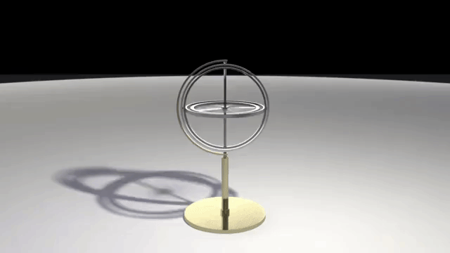
- By mounting this gyroscope, on a set of gimbal rings, the gyro is able to rotate freely in any direction.
Precession
- Precession is the tilting or turning of a gyro in response to a force.
-
The reaction to this force occurs at a point that is 90° later in the direction of rotation.
- This will cause small errors in the instruments
Powered
Attitude Indicator and Heading Indicator are Air Vacum Driven
Turn Coordinator is Electric driven
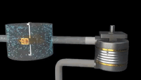
Vacuum System
- In simple terms, the engine-driven pump sucks air through the system. The air flows in from the inlet filter, normally located under your instrument panel, directly into the inlet ports on your attitude indicator and heading indicator.
- The suction gauge gives a differential pressure measured in inches of mercury.
Vacuum System
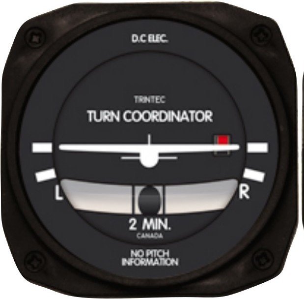
Turn Coordinator
System Operation
- Indicates the rate of roll and rate of turn.
- The gimbal in the turn coordinator is inclined; therefore, its gyro can sense both rates of roll and rate of turn.
Inclinometer: Indicates the quality of the turn. The ball should always be in the center while the airplane is turning. You center this ball using rudder inputs.
- A standard-rate turn is defined as a turn rate of 3° per second.
Angle Of Bank = (KTAS / 10) + 5
If inadequate right rudder is applied in a right turn, a slip results. Too much right rudder causes the aircraft to skid through the turn. Centering the ball results in a coordinated turn.
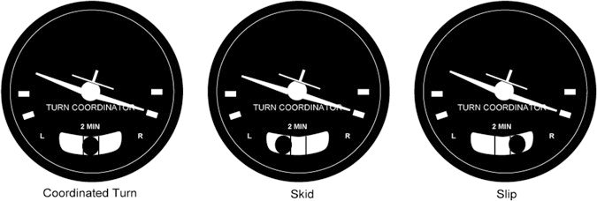
SLIP
SKID
- During a slip there's not enough rate of turn for the amount of bank
- Pilot needs to increase the amount of rudder input.
SLIP
- During a skid there's too much rate of turn for the amount of bank
- Pilot needs to decrease the amount of rudder input.
SKID
- During pre-flight, ensure that the inclinometer is full of fluid and has no air bubbles.
- The ball should also be resting at its lowest point.
- When taxiing, the turn coordinator should indicate a turn in the correct direction while the ball moves opposite the direction of the turn.
Instrument Check
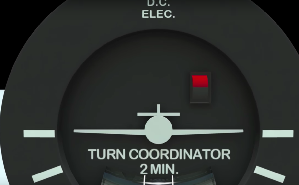
- For an electric turn coordinator, the main failure mode will be an electrical failure
System Error
- A red flag shows the instrument is in a non-operational status
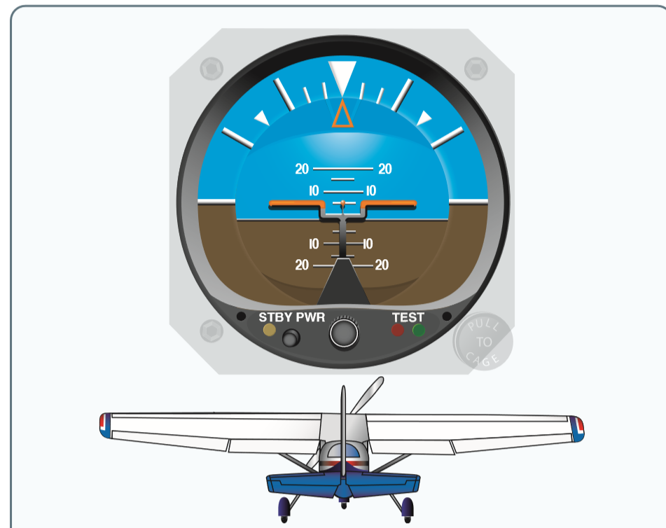
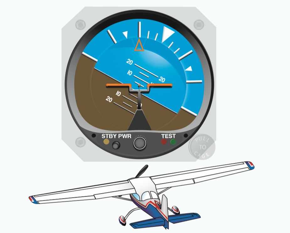
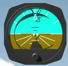
Attitude Indicator
Indicates the aircraft's position relative to the true horizon
Instrument Operation
-
The gyro in the attitude indicator is mounted in a horizontal plane and depends upon rigidity in space for its operation.
- The horizon bar represents the true horizon.
- A small symbolic aircraft is mounted in the instrument case so it appears to be flying relative to the horizon. A knob at the bottom center of the instrument case raises or lowers the aircraft to compensate for pitch trim changes as the airspeed changes.

Examples
- Instrument should be spun up and active within 5 minutes of engine start. In addition, there should be no more than 5 degrees of pitch and bank deviation.
- If the aircraft experiences and abrupt change in pitch or bank, it may cause inaccurate readings.
-
Limits in the banking plane are usually from 100° to 110°, and the pitch limits are usually from 60° to 70°. If either limit is exceeded, the instrument will tumble or spill and will give incorrect indications until realigned.
Limitations / Instrument Check
Instrument Errors
Turning: When initiating a turn the gyro will swing or move to the rear, again due to precession of centrifugal force against the gyro. Both errors are small and will correct themselves.
- These inherent errors are small and correct themselves within a minute or so after returning to straight-and-level flight and are less than half bar in width.
- Suction: When suction falls below 3.5" Hg, the instrument will become sluggish to move. Above 4.5"Hg, the attitude indicator will become more lively, and it will wear out much sooner.
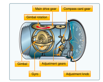
Heading Indicator
Instrument Operation
- The operation of the heading indicator depends upon the principle of rigidity in space. The rotor turns in a vertical plane and fixed to the rotor is a compass card.
- The gyro in a heading indicator is mounted in a single gimbal and spins in a vertical plane as the aircraft rotates around the gryoscope.
- Gyro heading indicators, with the exception of slaved gyro indicators, are not north seeking, therefore they must be manually set to the appropriate heading by referring to a magnetic compass.
The Earth constantly rotates at 15° per hour while the gyro is maintaining a position relative to space, thus causing an apparent drift in the displayed heading of 15° per hour.

Instrument Check
- While taxiing, the instrument should indicate turns in the correct direction.
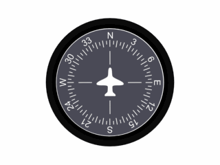
Instrument Errors
- Because of precession, caused by friction between the gyro and gimbals, the heading indicator drifts from its set position.
- The heading indicator may indicate as much as a 15° error for every hour of operation. It is recommended to check it every 15 minutes.
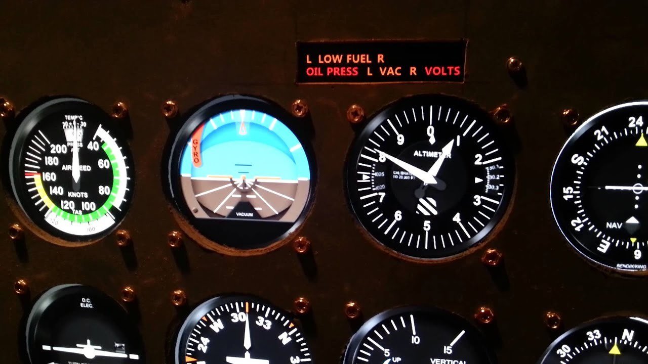
- Provides critical information to the pilot like low fuel, oil pressure, or failure of the vacuum pumps.
Annunciator Panel
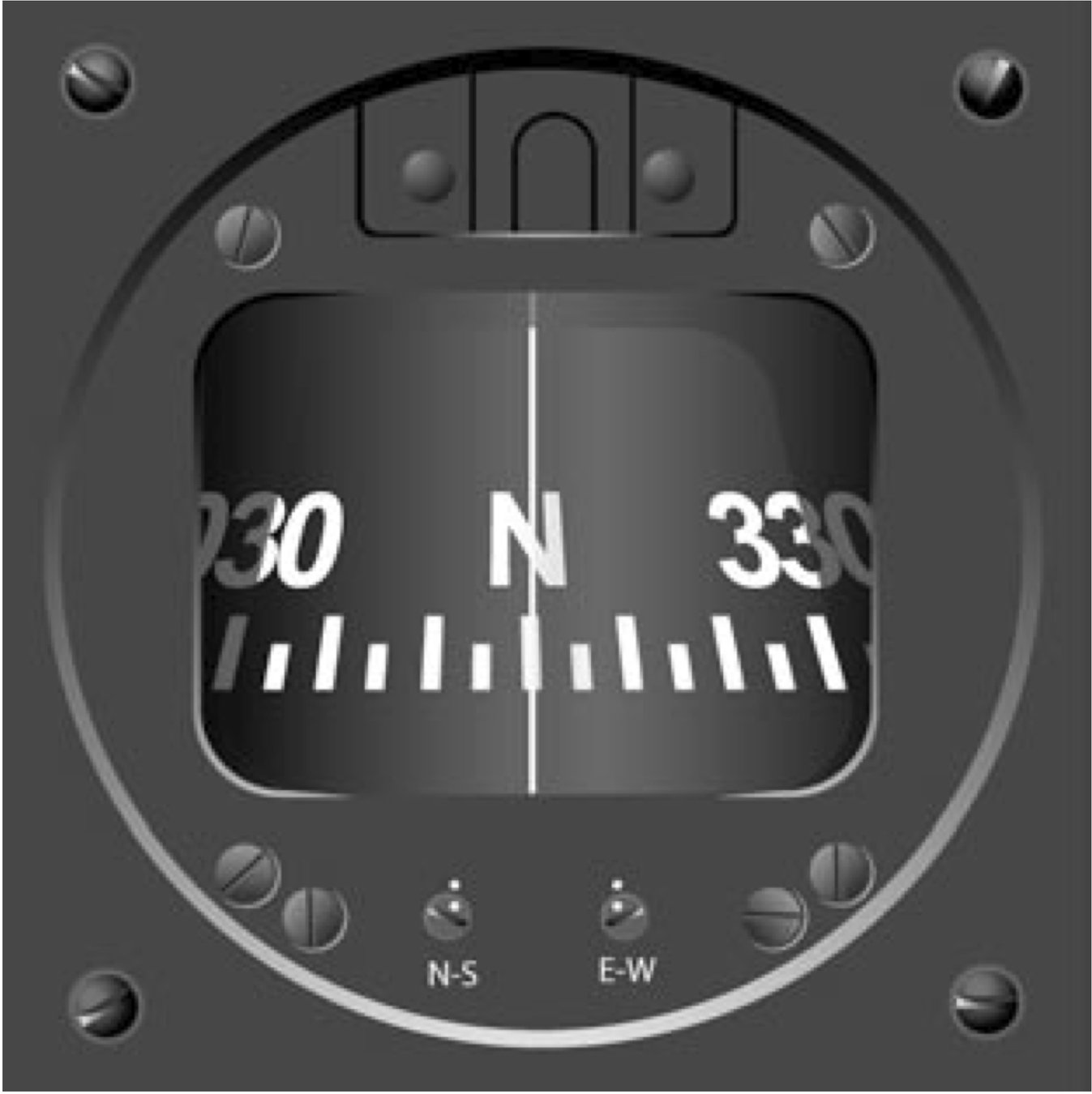
Magnetic Compass
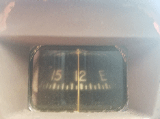
- One of the oldest and simplest instruments for indicating direction.
- A self-contained instrument that does not require electricity or any other mechanism to work.
Instrument Operation
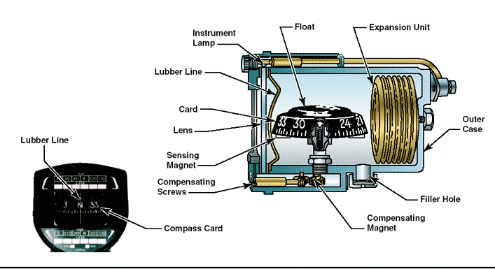
-
Has two small magnets attached to a metal float sealed inside a bowl of clear compass fluid similar to kerosene.
-
Magnets are mounted to the float, so they move freely and align with the Earth's magnetic field.
- A graduated scale, called a card, is wrapped around the float and viewed through a glass window with a lubber line across it
Instrument Errors
D
V
M
O
N
A
Deviation
Variation
Magnetic Dip
Oscillation
Northerly Turning Error
Acceleration Error
Deviation
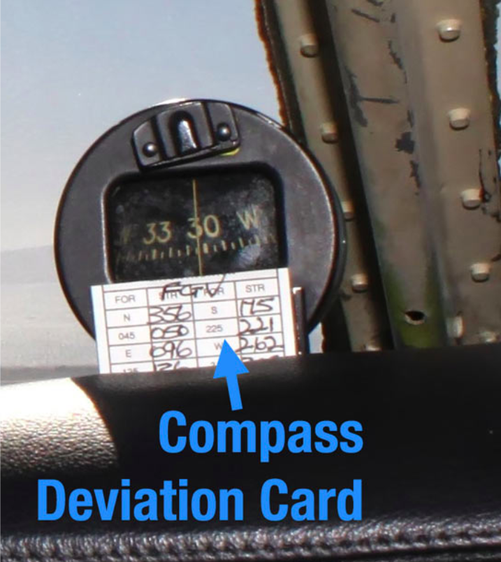
The occurrence of deviation is due to disturbances from other magnetic and electrical objects within the airplane itself.
An aviation maintenance technician (AMT) can minimize deviation error by performing the maintenance task known as “swinging the compass." Once this procedure is complete and the compass adjusted, the AMT records any remaining error on a compass correction card and places it in a holder near the compass.
Variation
- Angular difference between Magnetic North and True North
Oscillation
- Oscillation is caused by fluctuation of the compass during turbulence.
Magnetic Dip
- Earth's Magnetic Fields are located deep inside the planet.
- This will create the tendency of the compass to point down. The dip angle increases in a downward direction as you move towards the Magnetic North Pole and increases in an upward direction as you move towards the Magnetic South Pole.
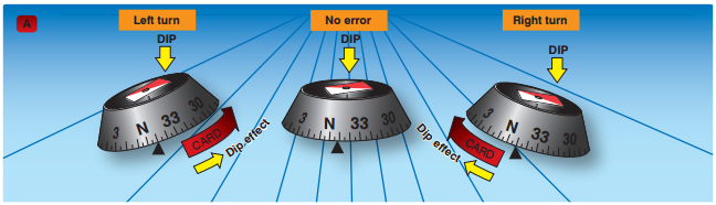
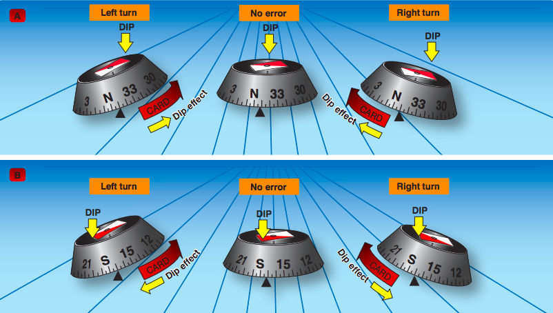
Northerly Turning Error
- The center of gravity of the float assembly is located lower than the pivotal point. As the airplane turns, the force that results from the magnetic dip causes the float assembly to swing in the same direction that the float turns. The result is a false northerly turn indication.
U
N
O
S
Remember
Undershoot
North
Overshoot
South
- Stop Turn = Latitude +/- Half bank angle
General rule:
Acceleration / Deceleration Error
- The magnetic dip and the forces of inertia cause magnetic compass errors when accelerating and decelerating on easterly and westerly headings.
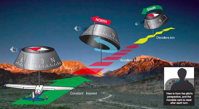
A
N
D
S
Accelerate
Decelerate
North
South
Remember
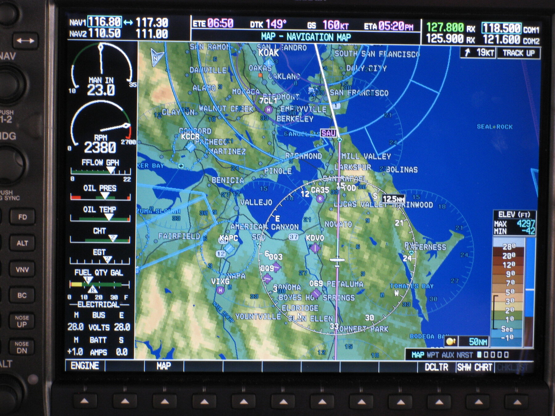
Electronic Flight Displays
- Digital flight instruments provide essentially the same information as analog instruments, but in a different format.
Primary Flight Display
Multifunction Display
PFD contains the primary flight instruments.
- The systems used in smaller airplanes typically have two screens:
MFD contains a variety of information such as maps, airports, terrain, and weather.
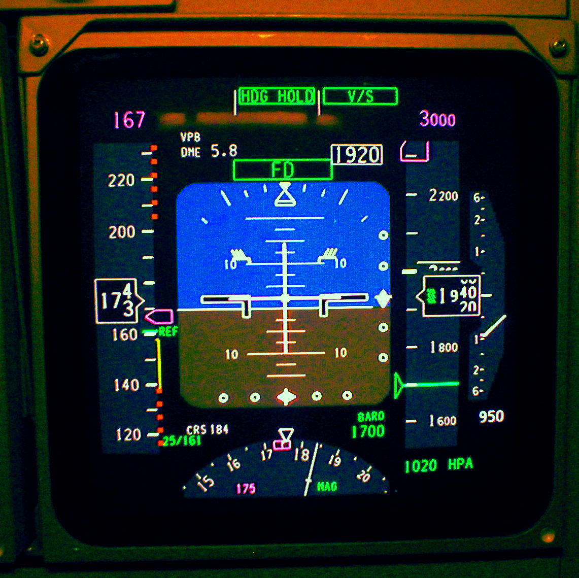
Primary Flight Displays
Airspeed
Vertical Speed Indicator
Attitude Indicator/Turn Coordinator
Heading Indicator
Slip/Skid Indicator
Altimeter
The Primary Flight Display utilizes the Attitude and Heading Reference System (AHRS) to provide precise information about an aircraft's attitude and heading.
AHRS employs inertial sensors, such as electronic gyroscopes, accelerometers, and magnetometers to measure all indications.
Attitude and Heading Reference System (AHRS)
Magnetometer
Mems Gyros
Ring Lasergyros
- Utilizes the Earth's magnetic field to operate as a magnetic compass.
- Minimizes certain errors linked to traditional compasses.
- Employs a flux valve or flux gate.
- No need to align with the compass manually.
- Sensitive electronic circuitry detects displacement as changes in capacitance.
- Measures capacitance between moving and non-moving sensor parts.
- Translates changes into signals for the AHRS to calculate attitude and rotation rates.
- Uses light to detect rotation & changes in attitude.
- A ring laser gyroscope splits a laser beam into two, directing each half around a triangular path in opposite directions.
- The aircraft rotation changes the wavelengths of the light beams.
Attitude Indicator
Roll Pointer
Aicraft Symbol
Roll Scale
Aicraft Symbol
Pitch Scale
Horizontal Situation Indicator
Current Heading
Arc Mode E-HSI
Compass Card
AHRS Errors
The AHRS continuously monitors itself, comparing data from various inputs and verifying the integrity of its information.
When the system identifies an issue, it displays a red X over the affected instrument's display.
AHRS Instrument Check
During taxi:
- Verify the operation of attitude and heading instruments during taxi.
- Confirm the heading indicator aligns with the compass.
- Ensure the heading and turn indicators respond correctly to turns.
- Check that the slip/skid indicator moves to the outside of the turn.
- Set and verify backup instruments.
Airspeed Indicator
Indicated Aispeed
Altimeter
Selected Aispeed
Indicated Airspeed
Altimeter Setting
Vertical Speed Indicator
Small Climb/Descent Rate
ADC Systems Errors
The ADC inputs include the pitot tube, static source, and outside air temperature probe to provide the necessary instrument indications.
If one or more of these sources stop providing input, a red X will appear over the affected instrument.
ADC Instrument Check
The ADC inputs include the pitot tube, static source, and outside air temperature probe to provide the necessary instrument indications.
If one or more of these sources stop providing input, a red X will appear over the affected instrument.
Electric System Failure
In the event of an electrical failure, backup power sources are available for the instrument system.
Understand how your electrical system operates and how to optimally utilize your remaining energy resources in case of an electrical failure.
Multifunction Display
The main feature of the MFD is the moving map, which displays additional information such as terrain, instrument procedures, weather, and traffic.
The MFD also includes:
- Airport information
- Flight plan data
- System indications
- Checklists
- Instrument charts