GL 3 Aerodynamic Principles

Rev 11/2024
Disclaimer
Students should use their textbooks, syllabus, and Airman Certification Standards (ACS) as their primary sources of information. EcFlight is an online training tool designed to simplify and enhance your ground school learning experience. However, it is not a substitute for FAA- or school-approved study materials. Before using these slides for study, always refer to your officially approved resources, such as the Jeppesen physical or electronic book and other FAA-approved materials.
Reference Books
- Pilot's Handbook of Aeronautical Knowledge(FAA-H-8083-25B). (2016). Oklahoma City, OK: United States Department of Transportation, Federal Aviation Administration, Airman Testing Standards Branch.
- Private Pilot Syllabus (10001292-002). (2012). Englewood, CO: Jeppesen.
- Cessna. (1976). Pilot's Operating Handbook(D1057-13). Wichita, KA: Cessna.
- Chapter 5 - Aerodynamics of Flight. (n.d.-a). https://www.faa.gov/sites/faa.gov/files/07_phak_ch5_0.pdf
Reference Multimedia
- The Efficient Engineer. (n.d.). Understanding Aerodynamic Lift. YouTube. https://www.youtube.com/watch?v=E3i_XHlVCeU
- (N.d.-b). Retrieved from https://edcraft.io/wp-content/uploads/2021/02/Newtons-laws.jpg.
- Infinity Learn NEET. (2017). Newton’s First Law of Motion | Forces and Motion | Physics | Infinity Learn. YouTube. https://www.youtube.com/watch?v=5oi5j11FkQg
- TED-Ed. (2023b). How do airplanes actually fly? - Raymond Adkins. YouTube. https://www.youtube.com/watch?v=p4VHMsIuPmk&t=192s
- flight-club. (2015). What is Drag?. YouTube. https://www.youtube.com/watch?v=stNKrsiw6UA&t=80s
- Pilot Institute Airplanes. (2023a). Kind of Flaps. YouTube. https://www.youtube.com/shorts/YVhwf7qDw4I
- Lauren Bitikofer. (2016). Dutchroll. YouTube. https://www.youtube.com/watch?v=2tgfkGiHhxs
- flight-club. (2021). Understanding Dutch Roll | Simple explanation. YouTube. https://www.youtube.com/watch?v=9Gt-IcCBiQ4
Index
Section A - Four Forces of Flight
Section B - Stability
Section C - Aerodynamics of Maneuvering Flight
Four Forces Of Flight
Weight
Lift
Thrust
Drag
- Four forces act on airplanes during flight.
-
The total of all upward force components equals the total of all downward force components and the total of all forward force components equals the total of all backward force components.
In steady flight:
Lift
Lift is the upward force generated by an airfoil.
How is lift created?
- Newton's Law
- Bernoulli's Principle
LIFT
Newton's Laws of Motion
- There are three laws that explain how lift is created.
- The third law has the most significant lift component.
An object at rest will stay at rest, and an object in motion will continue in a straight line at a constant speed unless acted upon by an external force.
- Example: An airplane at rest will remain at rest unless an external unbalanced force is applied.
Newton's First Law:
The acceleration of an object is directly proportional to the net force acting on it and inversely proportional to its mass.
- Formula: F = ma
- Example: A lighter aircraft requires less thrust to accelerate than a heavier one under the same force.
Newton's Second Law:
- weight
- thrust
+ weight
+thrust
For every action, there is an equal and opposite reaction.
- The third law has the most significant impact in lift production.
- Example: When a propeller pushes air backwards, it generates an equal forward thrust to propel the aircraft.
Newton's Third Law:
propeller pushes air backward
aircraft moving forward
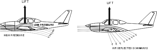
- The air moving past the wing is deflected downward by the shape and the motion of the wing. The wing exerts a force, or action, on the air. The reaction will be that the wing is then pushed upward by the air.
Bernoulli's principle
- The basic principle of airflow pressure differential is called Bernoullis's Principle.
- We can visualize this by observing air flowing through a tube with a narrow middle section, also called Venturi.
As velocity increases, pressure decreases.
This difference in pressure is what generates lift.
The shape of the wing is similar to the venturi. The air on the upper part of the wing accelerates, and its pressure decreases accordingly.
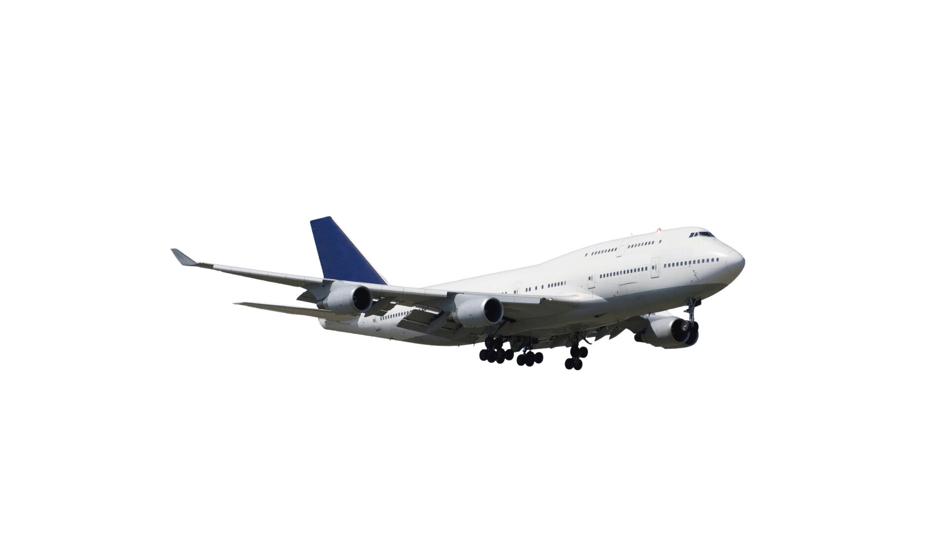
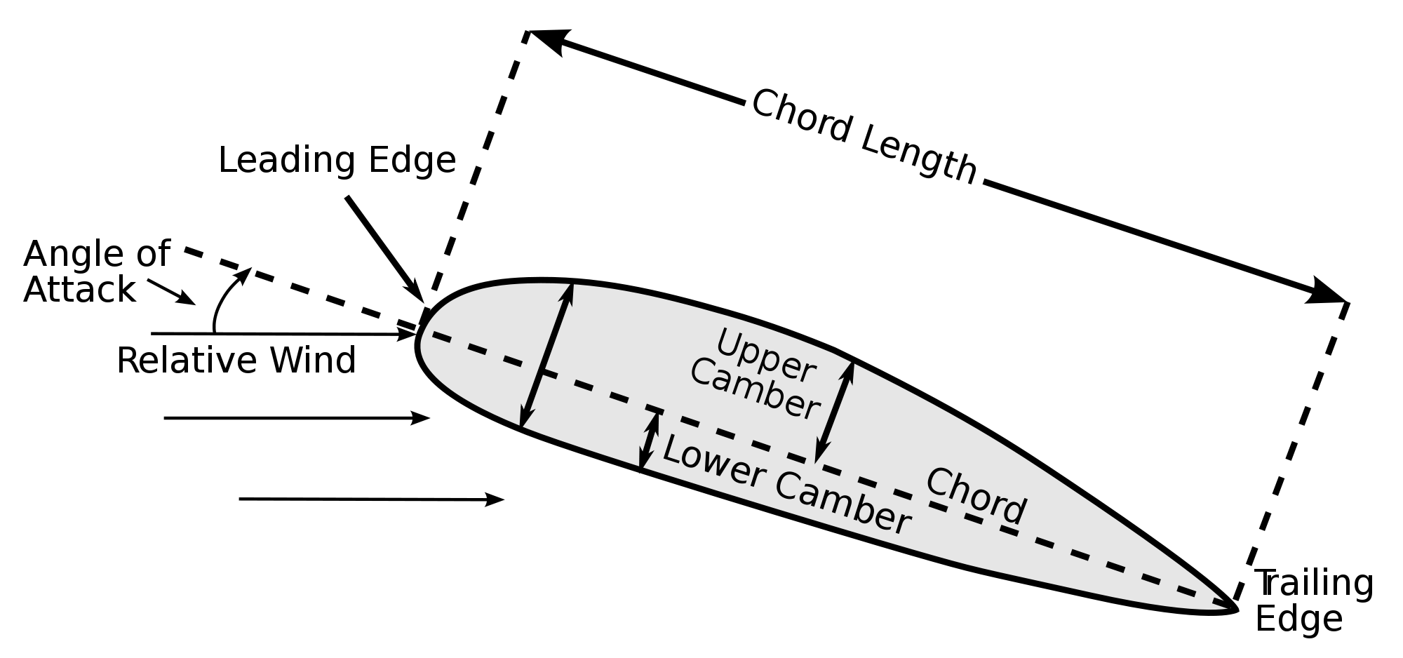
Airfoils
An airfoil is any surface, like a wing, that generates an aerodynamic force when air flows over it.
Airfoil Terminology
Airfoil Terminology
Bernoulli's principle
Newton’s Third Law of Motion
Theories Applied
Pilot Control of Lift
How Do Pilots Control Lift?
- Changing the airspeed: As the airplane speeds up, lift production increases.
- Changing the angle of attack: As the angle of attack increases, lift also increases.
Important: When speed decreases, you must increase the angle of attack to maintain the same amount of lift.
High-Lift Devices
- These are intended to improve the performance of airfoils at lower speeds.
- The most used devices are flaps.
Types of flaps
- Plain Flaps
- Split Flaps
- Slotted Flaps
- Fowler Flaps
Weight
WEIGHT
Weight:
- Opposes lift.
- Is the force of gravity acting through the center of the airplane toward the center of the Earth.
WEIGHT
Thrust
- Is the forward force that opposes drag.
- Is provided when the engine turns the propeller.
-
Newton's second law explains thrust with the following formula:
- Force =mass * acceleration
F=m*a
Thrust:
THRUST
Drag
- Drag is the force that opposes thrust and limits an airplane's forward speed.
-
There are 2 types of drag:
-
Parasite drag
-
Induced drag
-
Drag:
DRAG
Parasite drag
Parasite drag is produced by aircraft surfaces
- Skin friction drag
- Form drag
- Interference drag
Parasite Drag
There are three types of parasite drag:
Skin Friction Drag
Skin drag occurs when airflow surrounding an object is disturbed by imperfection on the surface or skin around where the air is flowing.
Form Drag
Form drag is the portion of parasite drag generated by the aircraft due to its shape and airflow around it.
Interference Drag
Interference drag comes from the intersection of airstreams that creates eddy currents, turbulence, or restricts smooth airflow.
For example: the intersection of the wing and the fuselage.
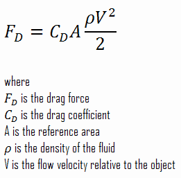
Induced Drag
- Induced drag results from the generation of lift.
- Therefore, if the pilot increases lift, it will also increase the square of the induced drag.
Drag Formula
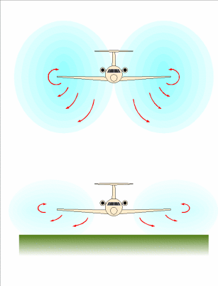
Ground Effect
-
Ground effect is due to the air that is trapped between the wing and the landing surface as if there were an air cushion.
- Due to the interference of the ground.
- Expect ground effect when less than one wingspan above the ground
What can you encounter when leaving ground effect?
- Requires an increase in AOA
- Increased induced drag and more thrust required
- Decrease in stability and a nose-up change in moment
- Increase in indicated airspeed
Stability
Dynamic Stability
Static Stability
Stability is the inherent quality of an aircraft to correct for conditions that may disturb its equilibrium and to return to or to continue on the original flight path.
Static Stability
Static stability is the initial tendency, or direction of movement, back to equilibrium.
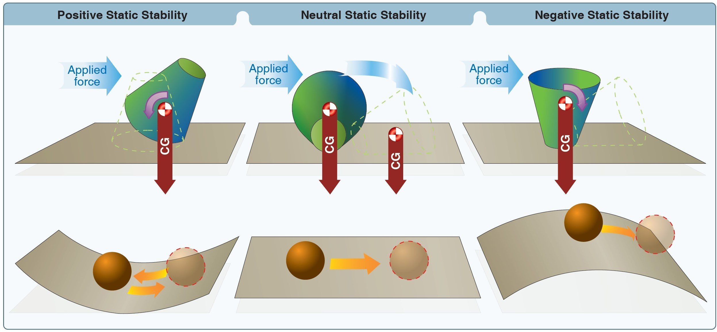
3 Types
The initial tendency of the aircraft to return to the original state of equilibrium after being disturbed.
Positive Static Stability
The initial tendency of the aircraft to remain in a new condition after its equilibrium has been disturbed.
Neutral Static Stability
The initial tendency of the aircraft to continue away from the original state of equilibrium after being disturbed.
Negative Static Stability
Dynamic Stability
Dynamic stability refers to the aircraft's response over time
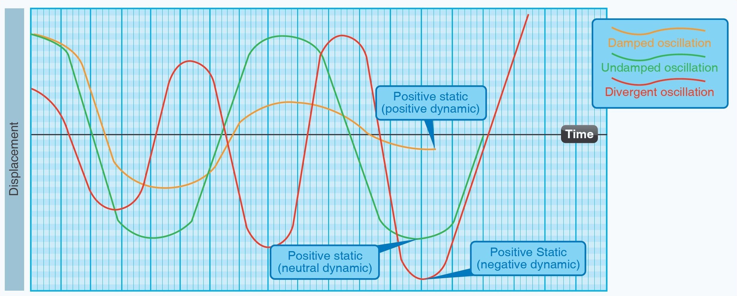
Positive Dynamic Stability
- The tendency of the aircraft to return to equilibrium over time
Once displaced, the displaced object neither decreases nor increases in amplitude.
Neutral Dynamic Stability
The motion of the displaced object increases and becomes more divergent over time.
Negative Dynamic Stability
- Controllability: Ability to respond to the pilot’s control, especially with regard to flight path and attitude.
Stability Affects Two Areas:
- Maneuverability: Quality of an aircraft to support stresses imposed by maneuvers.
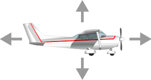
Three Axes of Flight
The three axes pass through the center of gravity (CG)
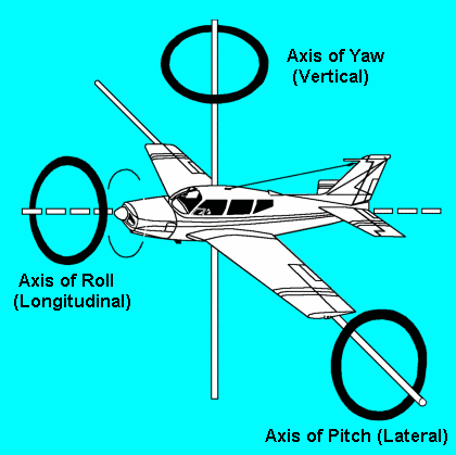
- The airplane’s attitude (rotation around the three axes) is controlled by the deflection of the primary flight controls.
- These are hinged, moveable surfaces attached to the trailing edge of the wings and vertical and horizontal stabilizers
Lateral Axes
The rotation about the lateral axis is called pitch. This axis changes the vertical direction of the aircraft.
Vertical Axes
The rotation about the vertical axis is called yaw. This axis changes the direction of the nose of the aircraft from side to side.
Longitudinal Axes
The rotation about the longitudinal axis is called roll. This axis changes the movement of the aircraft's wings.
Video By: shidifu111 Steve Karp
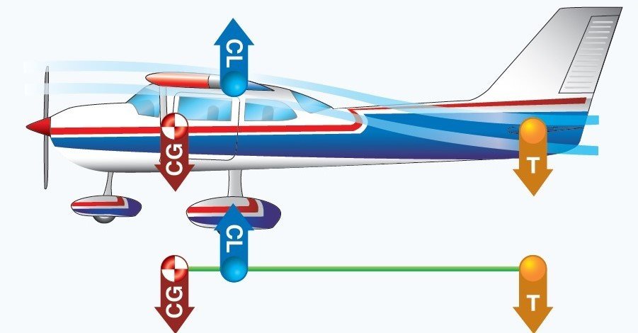
Longitudinal Stability (Pitch)
Longitudinal stability is a quality that makes an aircraft stable about its lateral axis. (Pitch).
1. Location of the wing with respect to the CG.
2. Location of the horizontal tail surfaces with respect to the CG.
3. Area or size of the tail surfaces.
Longitudinal stability is determined by:
1. Location of the wing with respect to the CG
- The CG is usually located slightly forward of the center of lift.
- This loading condition causes a nose-down tendency in flight, which is desirable during flight at a high AOA and slow speeds.
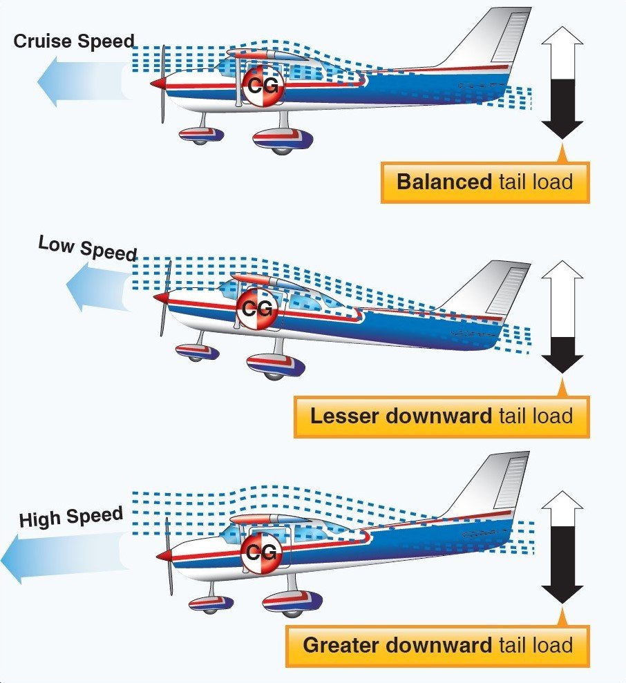
2. Location of the horizontal tail surfaces with respect to the CG.
- Compensation for this nose heaviness is provided by setting the horizontal stabilizer at a slight negative AOA.
- The downward force thus produced holds the tail down, counterbalancing the “heavy” nose.
3. Area or size of the tail surfaces.
- The larger the area of the tail surfaces, the greater force will produced.
Center of Gravity Position
Center of Gravity Limits
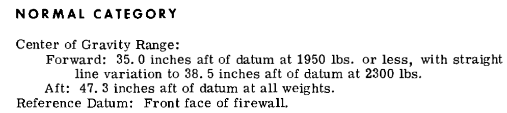
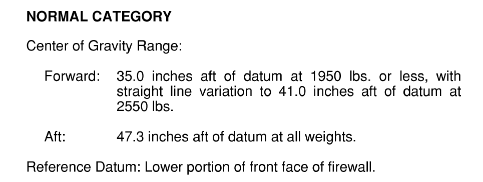
All airplanes have a maximum forward and aft CG limits that can be found on the POH of the respective aircraft. As long as you load your plane within the CG range, and given normal flight conditions, longitudinal stability and control of the airplane will be achieved.
C 172 M
C 172 SP
- Increased Elevator Control: The arm between the CG and the elevator is greater (greater moment obtained).
- Increased Stall Speeds: The increased tail downforce is translated into additional weight that the wings will support. Therefore, the airplane will fly at higher angle of attack for any given speed.
- Decreased Cruising Speed: Greater angle of attack for any given speed means greater drag produced.
Forward CG Effects
- Decreased Elevator Control: The arm between the CG and the elevator is shorter (less moment obtained).
- Decreased Stall Speeds: The decrease tail downforce is translated into additional weight the wings will support. Therefore the airplane will fly at lower angle of attack for any given speed.
- Increased Cruising Speed: Lower angle of attack for any given speed means lower drag produced.
Aft CG Effects
Forward CG
- Increased Longitudinal Stability
- Higher Stall Speed
- Lower Cruise Speed
- Nose Heaviness
- Difficult or Impossible to Flare for Landing
Aft CG
- Decreased Longitudinal Stability
- Lower Stall Speed
- Higher Cruise Speed
- Poor Stall Recovery
- Less Stable at all Airspeeds
The actual location of the CG can be altered by many variable factors and is usually controlled by the pilot. Placement of baggage and cargo items has an influence on the CG location. The assignment of seats to passengers can also be used as a means of obtaining a favorable balance. Fuel burn can also affect the CG based on the location of the fuel tanks.
Review
Lateral Stability (Rolling)
- The aircraft rolls along the longitudinal axis
- There are four main design factors make an aircraft laterally stable:
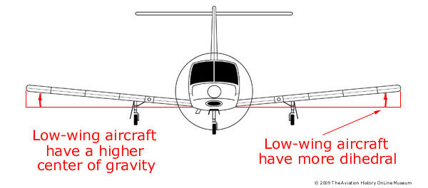
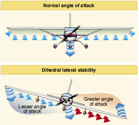
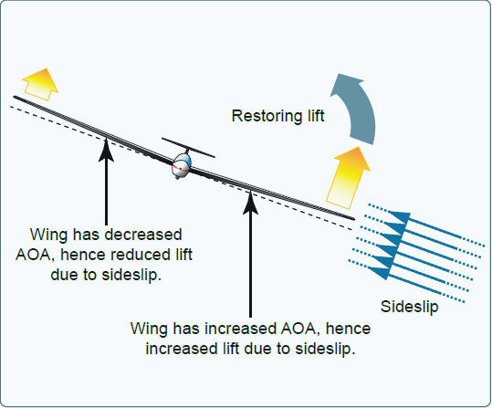
Dihedral
The dihedral angle is the angle that each wing makes with a parallel line of the lateral axes
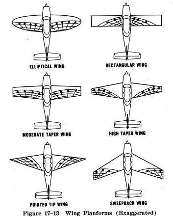
Sweepback
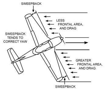
- When a disturbance causes an aircraft with sweepback to slip or drop a wing, the low wing presents its leading edge at an angle that is more perpendicular to the relative airflow.
- As a result, the low wing acquires more lift, rises, and the aircraft is restored to its original flight attitude.
Keel Effect
A high wing aircraft always tends to turn the longitudinal axis of the plane into the relative wind.
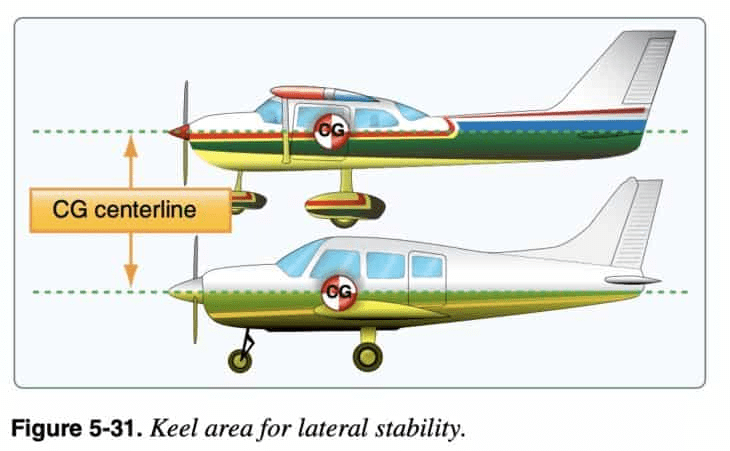
Weight Distribution
The combination of weight and the pressure of the airflow against the upper portion of the keel area (both acting about the CG) tends to roll the aircraft back to wings-level flight.
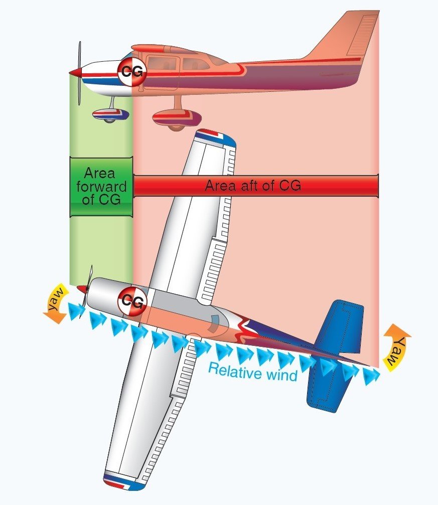
Directional Stability (Yawing)
Yawing is stability about the aircraft’s vertical axis
1. Swept-back wings.
2. Dutch roll.
3. Vertical stabilizer acts like the tail feathers on an arrow.
A directionally stable aircraft tends to remain on its course in straight and level flight."
Determined by:
Swept-Back Wings
-
When turbulence or rudder application causes the aircraft to yaw to one side, the opposite wing presents a longer leading edge perpendicular to the relative airflow.
-
The airspeed of the forward wing increases and it acquires more drag than the back wing.
- The additional drag on the forward wing pulls the wing back, turning the aircraft back to its original path.
Interaction of Lateral and Directional Stability
- The interaction between lateral and directional stabilizing design elements can sometimes reveal potentially undesirable effects.
- The most common are the dutch roll and spiral instability.
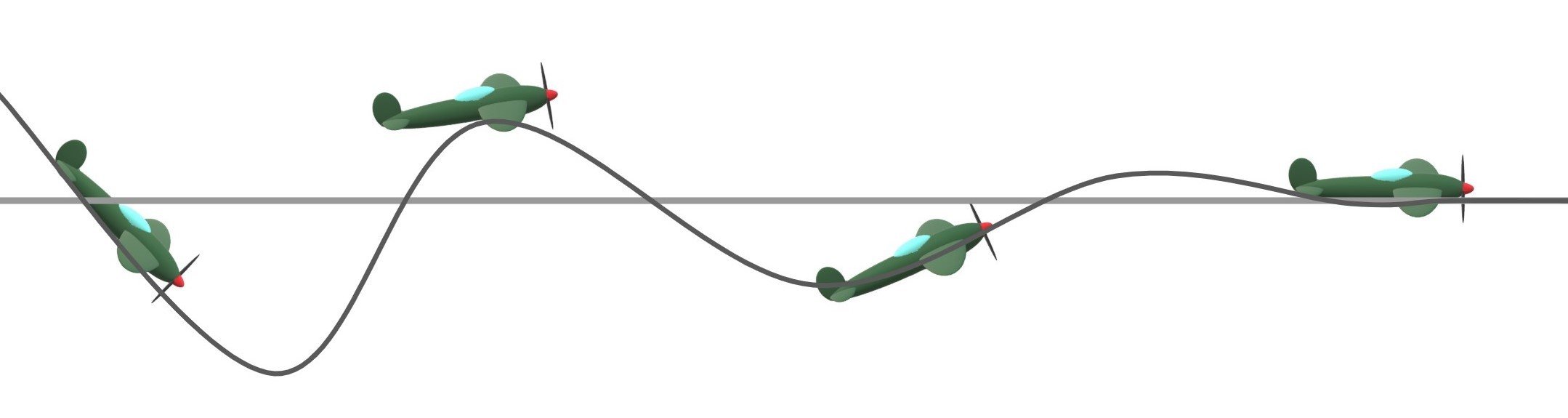
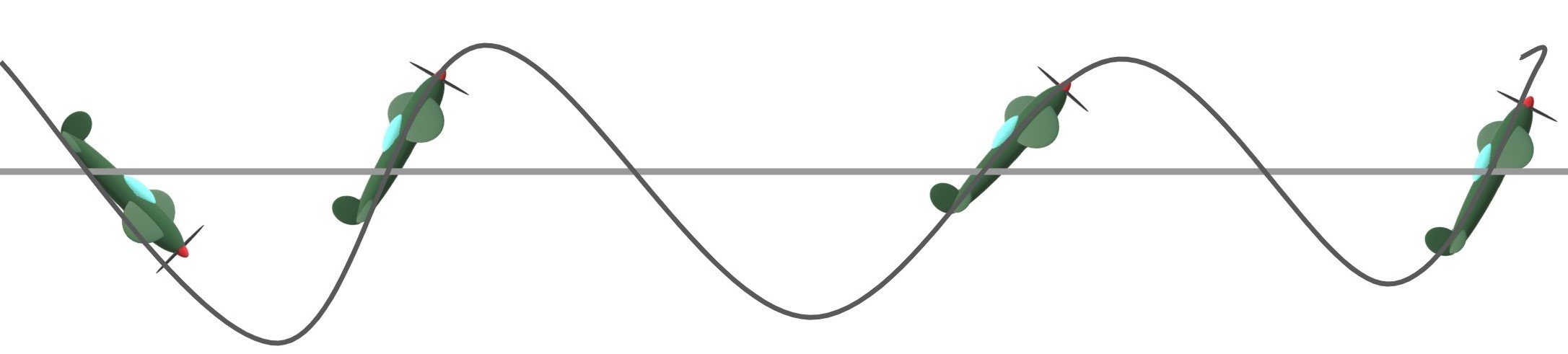
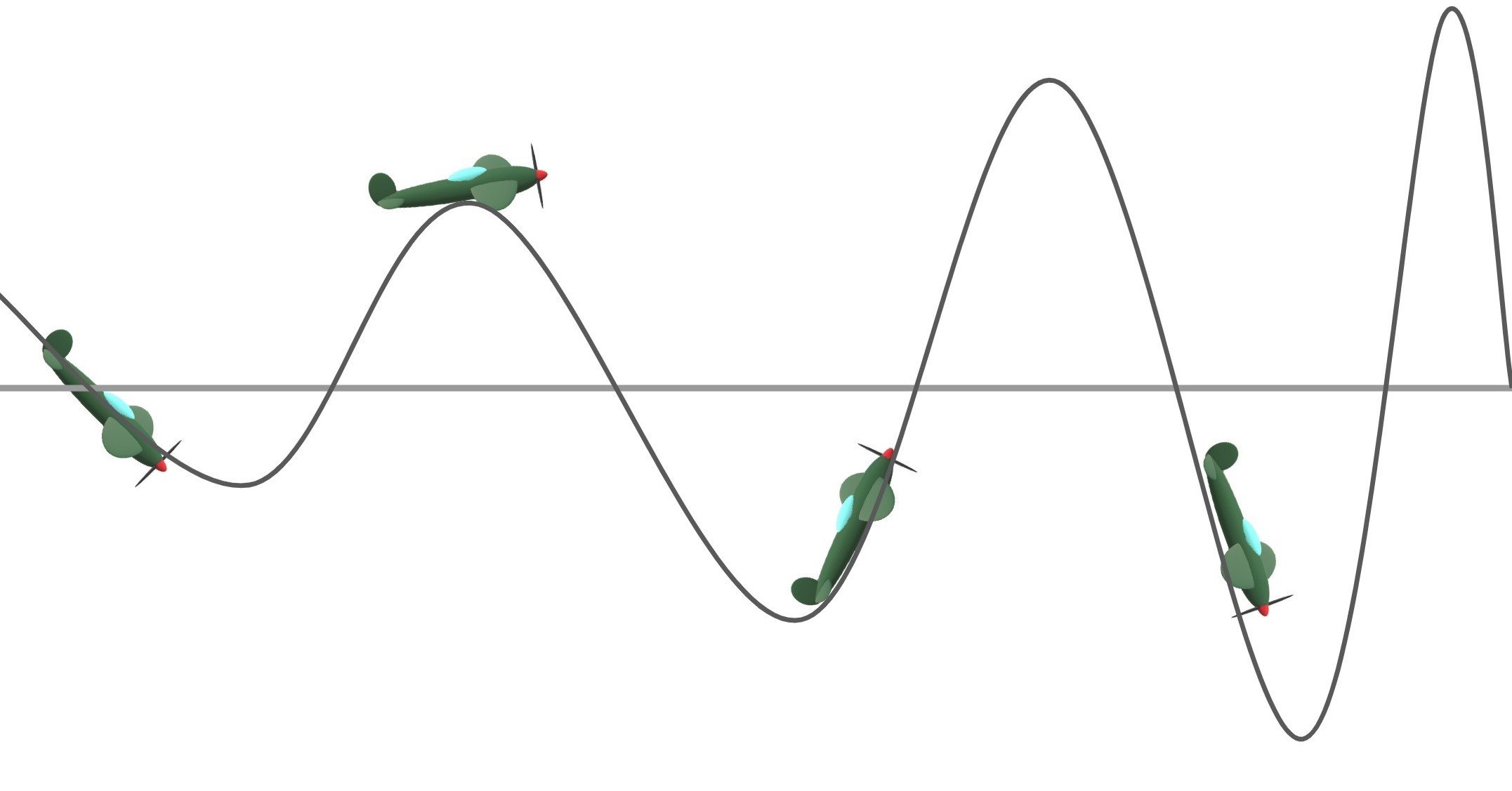
Dutch Roll
A combined sequence of rolling/yawing oscillations
- The result of strong lateral stability and weak directional stability
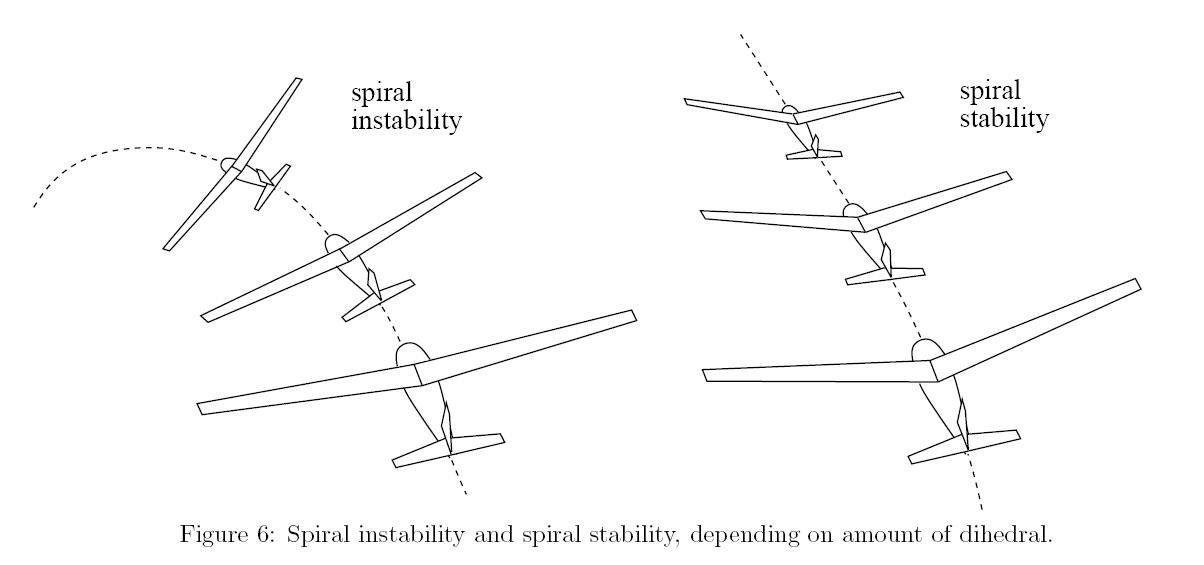
Spiral Instability
Spiral instability exists when the static directional stability of the aircraft is very strong as compared to the effect of its dihedral in maintaining lateral equilibrium.
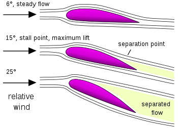
Stalls
- The stalling AOA is known as CL-MAX critical AOA.
- An airfoil always stalls at the same AOA.
- A stall can occur at any pitch attitude or airspeed.
- On straight-wing aircraft, the wing is designed to stall at the wing root first.
Stall Causes & Types
- Caused by the separation of airflow from the wing’s surface brought by exceeding the critical AOA.
- A stall can occur at any airspeed.
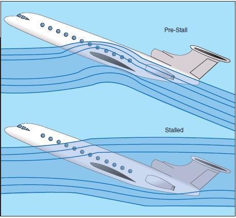
This critical AOA varies from 16° to 20° depending on the aircraft’s design.
Stall Recognition and Recovery
Stall Recognition
1. Less control effect/mushy feeling at the controls
2. Reduction in control surface effectiveness
3. Stall horn
4. Buffeting of controls
Stall Recovery
-
Decrease the angle of attack
-
Smoothly apply maximum allowable power
- Adjust the power as required
Stall in a C172
The wing is designed so that the angle of incidence is greater at the wing roots and decreases across the span, becoming lowest at the wing tip.
This is usually to ensure that at stall speed the wing root stalls before the wing tips, providing the aircraft with continued aileron control and some resistance to spinning.
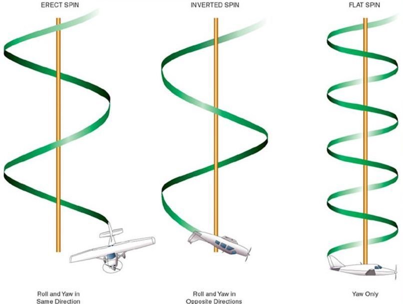
Spins
What is a Spin
- A stabilized spin is no different from a stall in any element other than rotation.
- The cause of a spin is an uncoordinated stall.
Spin Types Are:
- Erect
- Inverted
- Flat
Spin Phase
1
2
3
4
Spin Recovery
Always follow the standard procedures in the specific POH of the aircraft, but the PARE acronym is a good one to remember for spin recovery!
Power to idle
Ailerons neutral
Rudder opposite
Elevator forward
Aerodynamics of Maneuvering Flight
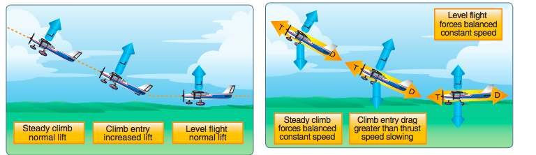
Climbing Flight
- Raising the aircraft’s nose increases the AOA and momentarily increases the lift.
- Lift at this moment is now greater than weight and makes the aircraft begin to climb.
Lift
4.000LB
2.300LB
Weight
Factors Affecting Climb Performance
- Absolute Ceiling: When the best rate of climb is zero and the airplane cannot climb any higher.
- Service Ceiling: Pressure altitude where the maximum rate of climb is 100 f.p.m.
Left Turning Tendencies
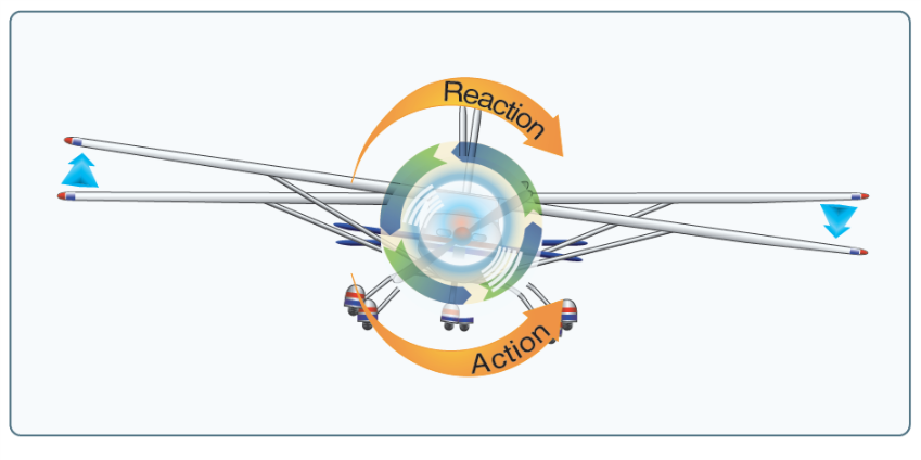
Torque
- Newton’s Third Law of Physics (for every action there is an equal and opposite reaction). When applied to the aircraft, this means that as the internal engine parts and propeller are revolving in one direction, an equal force is trying to rotate the aircraft in the opposite direction.
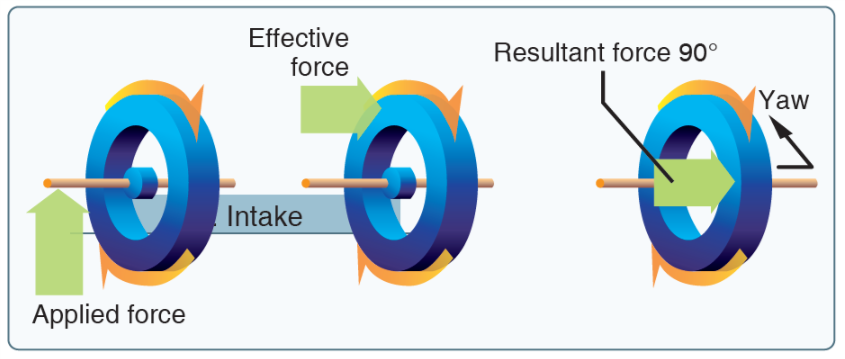
Gyroscopic Precession
- Precession is the resultant action, or deflection, of a spinning rotor when a deflecting force is applied to its rim.
- When a force is applied, the resulting force takes effect 90° ahead of and in the direction of rotation.
- The rotating propeller of an airplane makes a very good gyroscope and thus has similar properties.
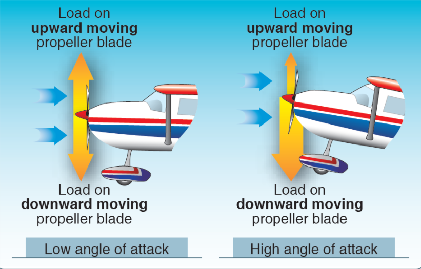
P- Factor
- When an aircraft is flying with a high AOA, the “bite” of the downward moving blade is greater than the “bite” of the upward moving blade.
- This moves the center of thrust to the right of the prop disc area, causing a yawing moment toward the left around the vertical axis.
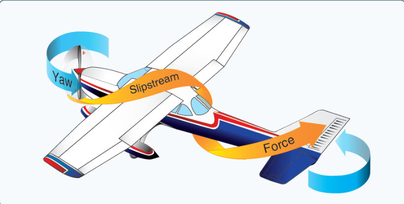
Spiraling Slipstream
- The high-speed rotation of an aircraft's propeller creates a corkscrew or spiraling rotation to the slipstream.
- When this spiraling slipstream strikes the vertical fin, it causes a yawing moment about the aircraft’s vertical axis.
- As the forward speed increases, however, the spiral elongates and becomes less effective. The corkscrew flow of the slipstream also causes a rolling moment around the longitudinal axis.

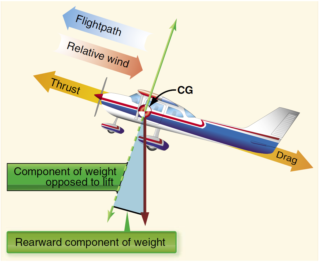
Descending Flight
Do not confuse a reduction in lift with the inability to generate sufficient lift to maintain level flight "
- As forward pressure is applied to the control yoke to initiate the descent, the AOA is decreased momentarily.
-
- As the AOA decreases, it causes the total lift to drop. Consequently, weight at this instance becomes greater than lift, causing the aircraft to descend.
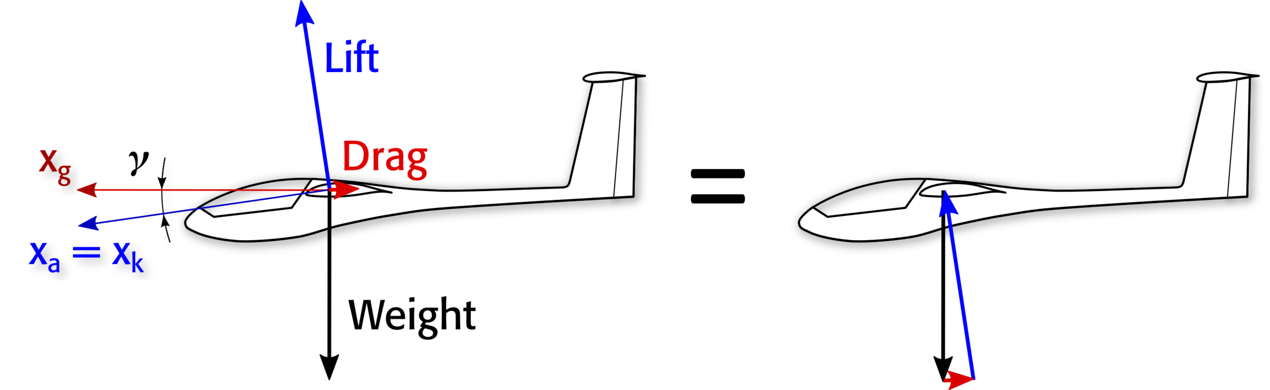
Unaccelerated Descent
= 2.500 LB
= 2.100 LB
- Achieved at glide speed by adjusting the angle of attack.
- At an unaccelerated descent, the thrust equals zero.
Turning Flight
- An aircraft, like any moving object, requires a sideward force to make it turn. The force of lift during a turn is separated into two components at right angles to each other.
- One component, which acts vertically and opposite to the weight (gravity), is called the “vertical component of lift.”
- The other, which acts horizontally toward the center of the turn, is called the “horizontal component of lift” or centripetal force.
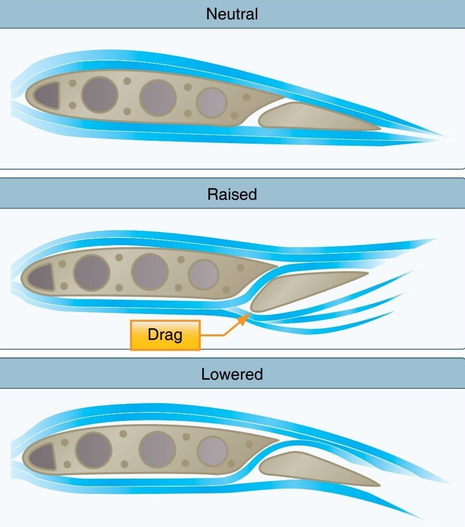
Adverse Yaw
- Since the downward deflected aileron produces more lift, as evidenced by the wing raising, it also produces more drag. This added drag causes the wing to slow down slightly.
- From the pilot’s perspective, the yaw is opposite the direction of the bank.
- Fun fact: a frise type aileron will reduce adverse yaw
Frise Type Aileron
- With a frise-type aileron, pressure is applied to the control wheel, or control stick, the aileron that is being raised pivots on an offset hinge.
- It helps equalize the drag created by the lowered aileron on the opposite wing & reduces adverse yaw.
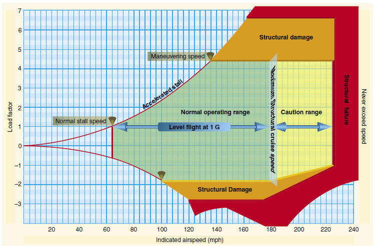
Load Factor
- Ratio of the load support by the airplane's wings to the actual weight of the aircraft and its contents.
- The load factor is measured in Gs (acceleration of gravity)
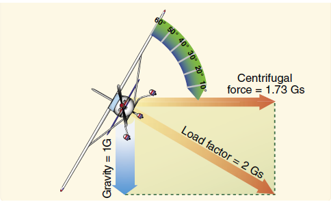
- For example: If an aircraft is pulled up from a dive, subjecting the aircraft to 3 Gs, the Pilot would feel pressed down into the seat with a force equal to three times his or her weight.
1. It is possible for a pilot to impose a dangerous overload on the aircraft structures.
2. An increased load factor increases the stalling speed and makes stalls possible at seemingly safe flight speeds.
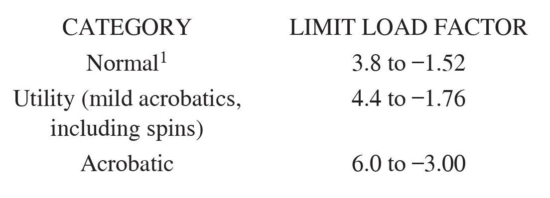
Limits of Load factor
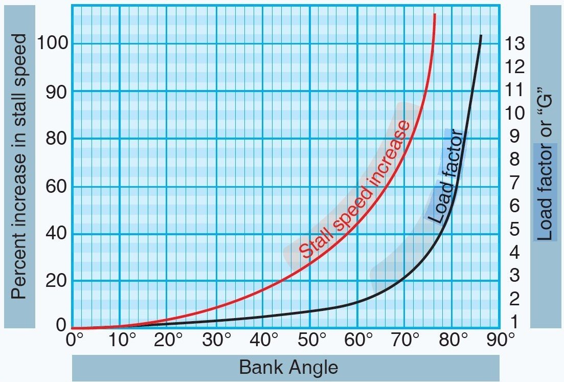
Load Factor in a Turn
The load factor imposed on an airplane will increase as angle of bank increases.
Load Factor and Stall Speed
Increasing the load factor will cause an airplane to stall at a higher airspeed.
Maneuvering Speed
The speed at which you can use full, abrupt control movement without over-stressing the airframe.
Energy Management
Energy Management
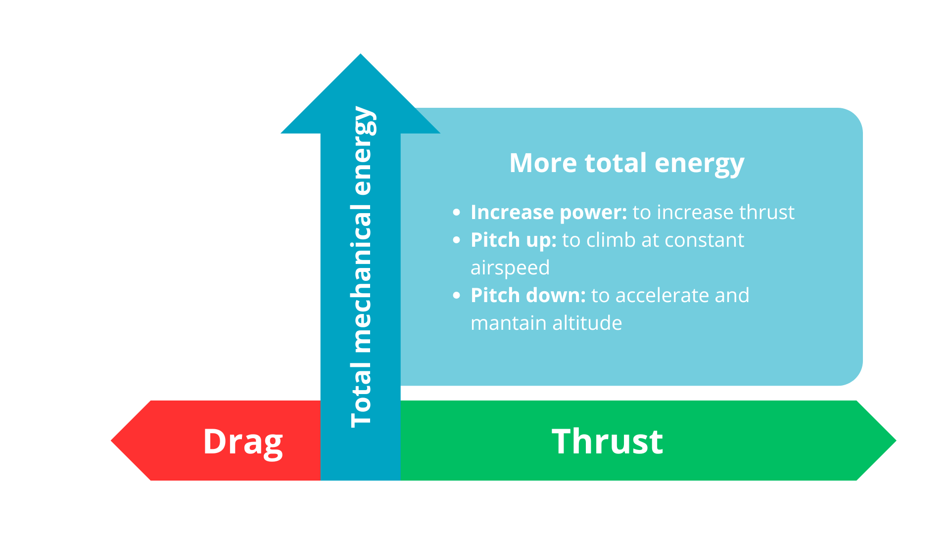
- Energy management is the use of power and pitch to manage the airplane's energy state of altitude and airspeed.
Total Mechanical Energy = Potential Energy + Kinetic Energy
- When energy is exchanged: as altitude increases, airspeed decreases, and vice versa
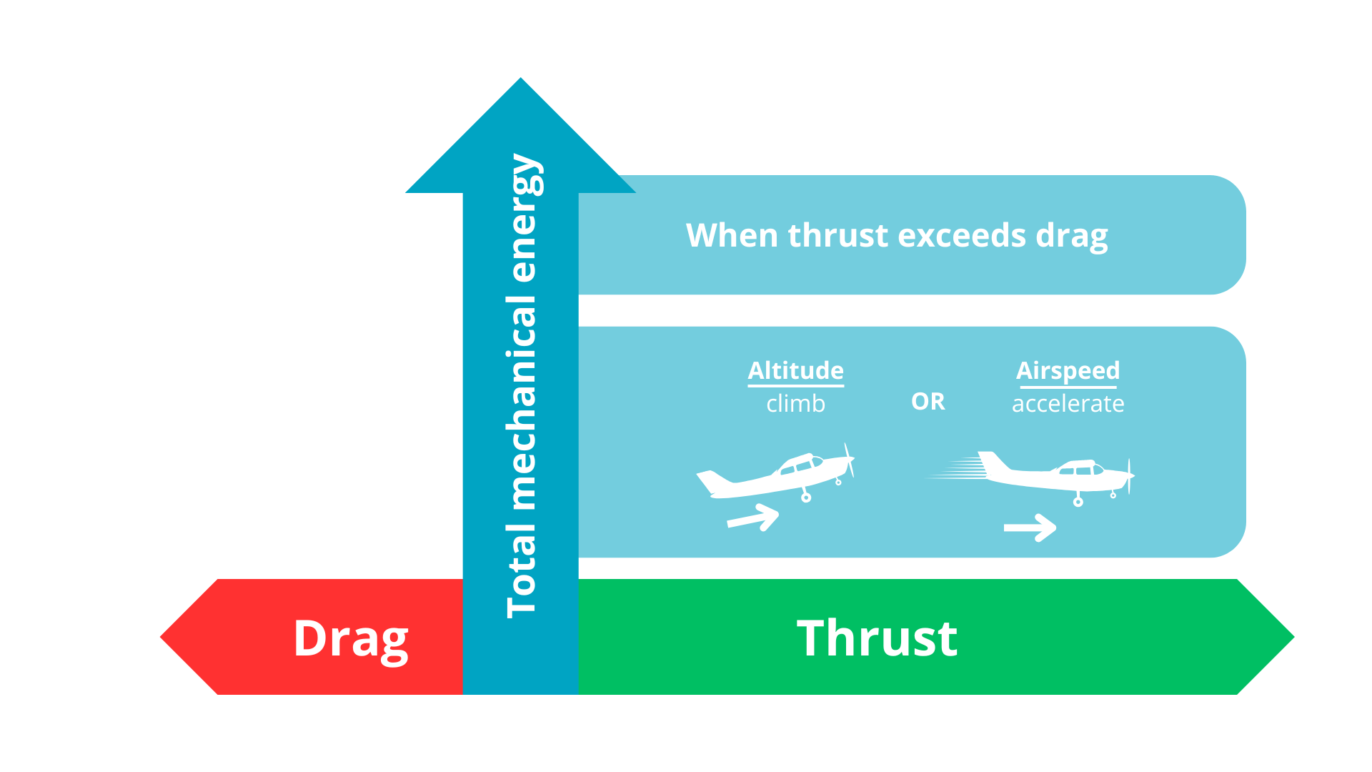
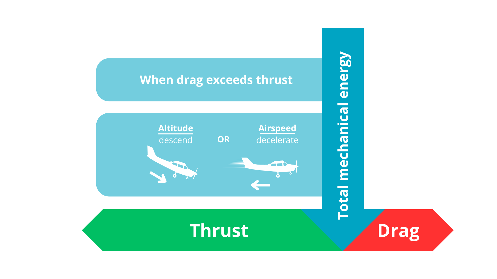
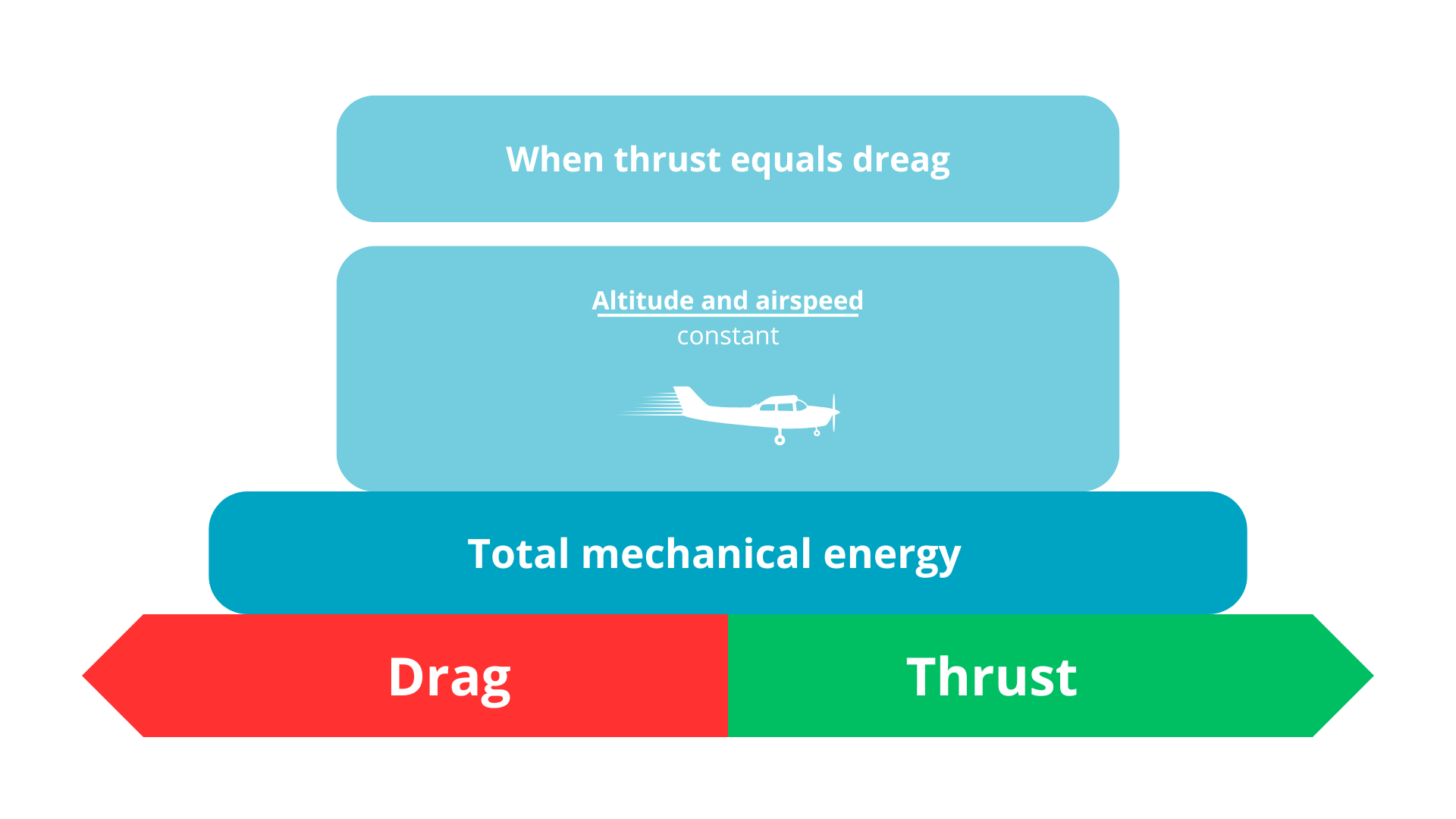
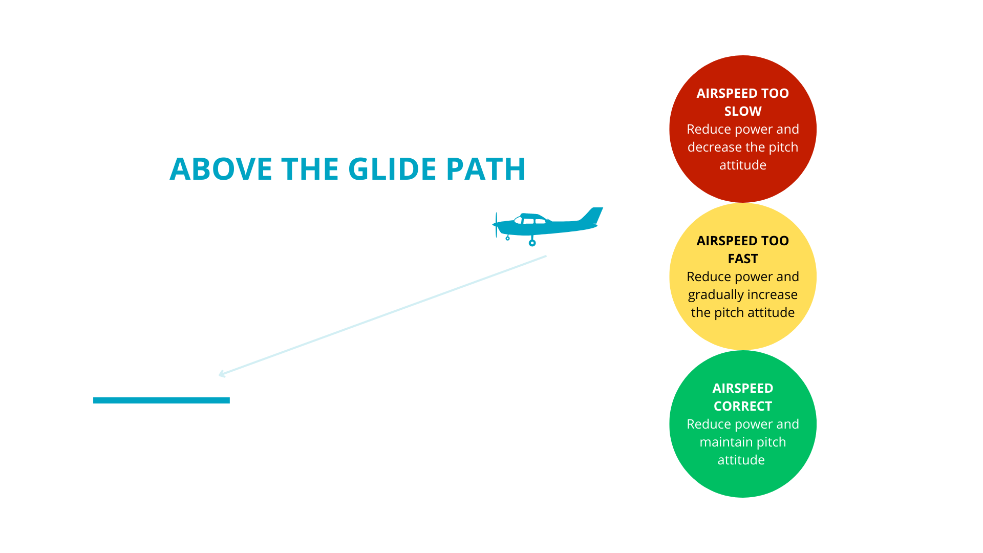
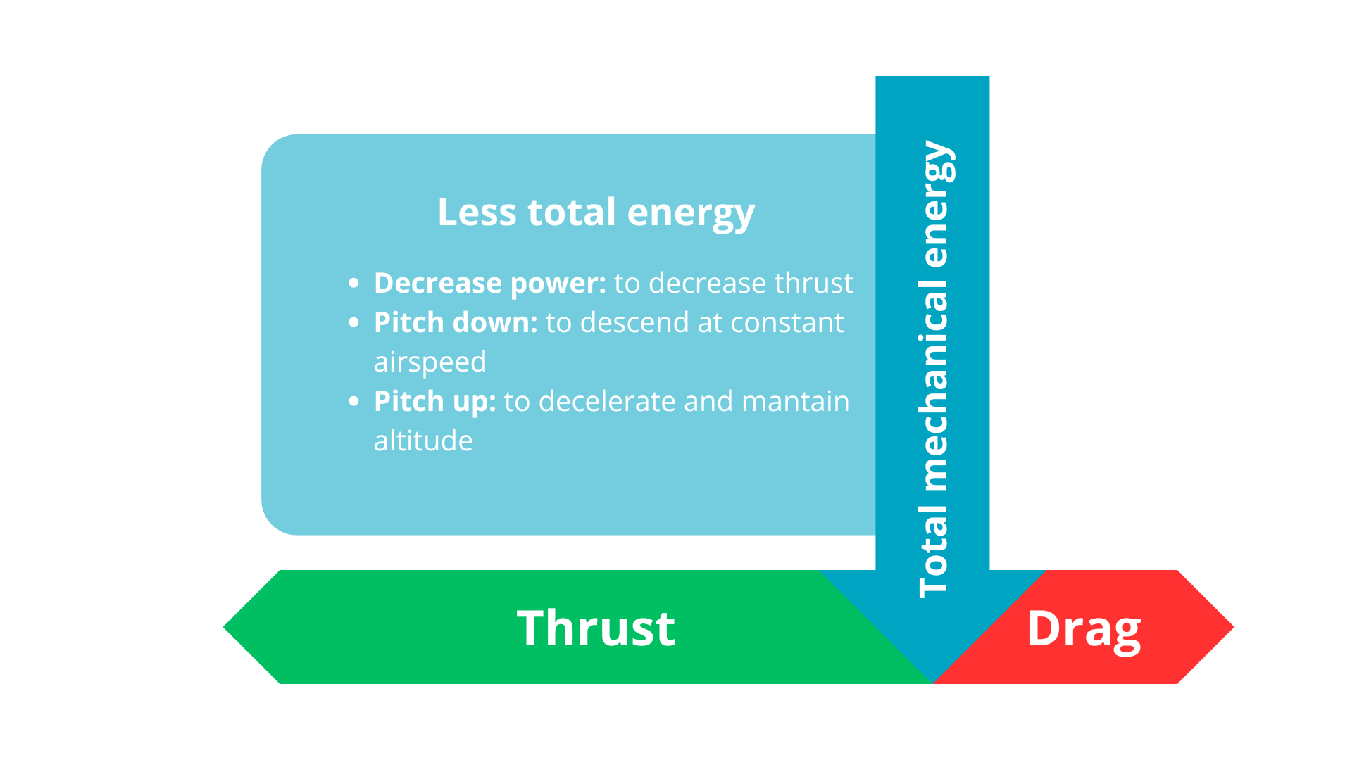
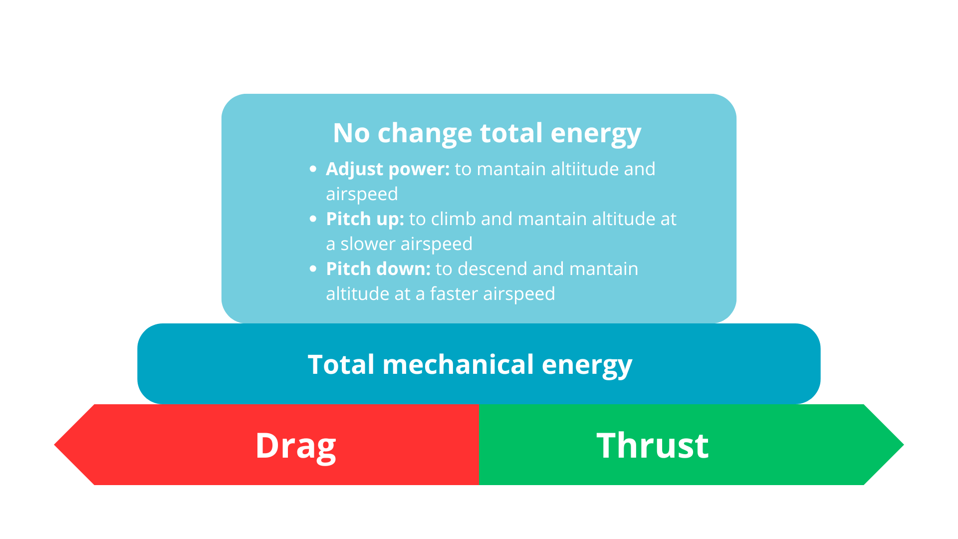
RULES OF ENERGY CONTROL
ENERGY MANAGEMENT ERROS
- Total energy errors: occur when the airplane has too much or too little energy.
To correct: increase or decrease energy by adding or reducing power.
- Energy distribution errors: the airplane has the right amount of total energy, but the distribution over altitude and airspeed is incorrect.
To correct: adjust pitch to exchange energy between altitude and airspeed.
WHEN LANDING
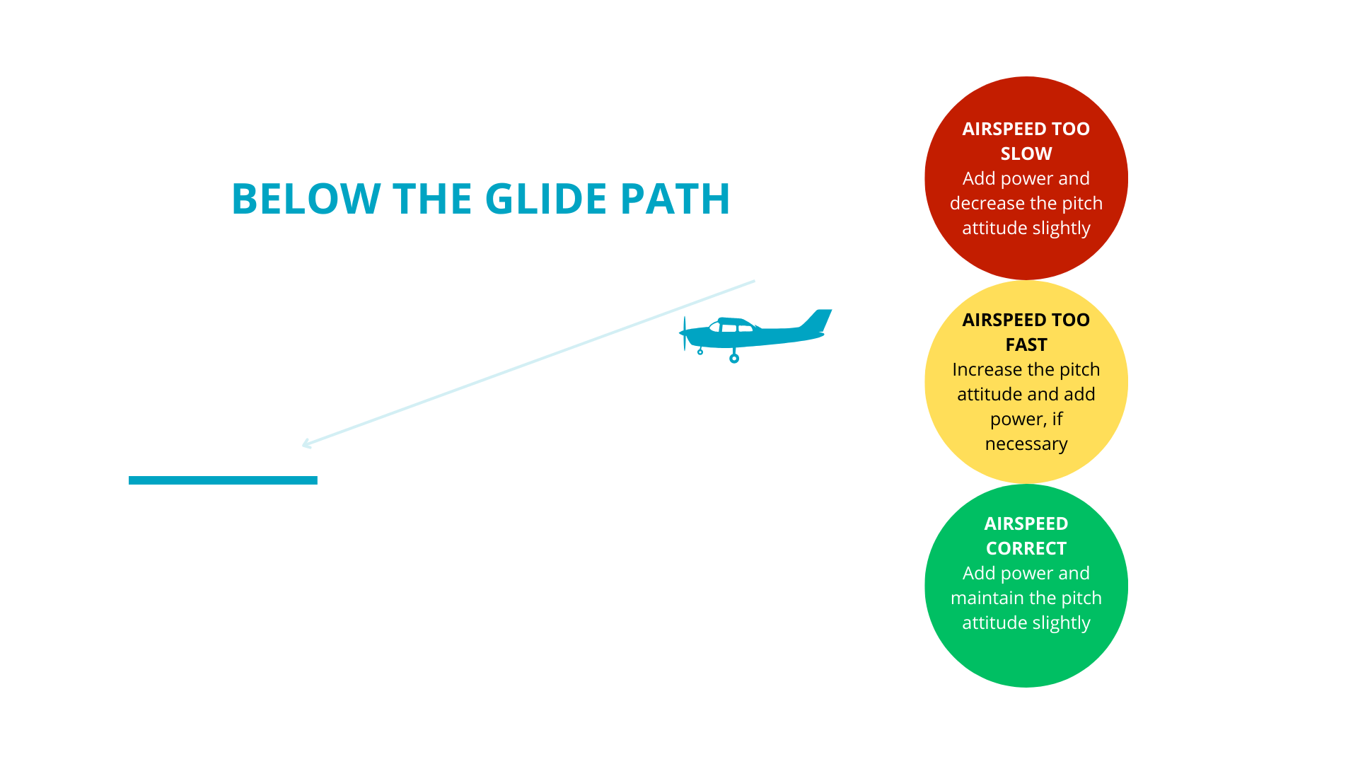
WHEN LANDING