Learn to program hardware with a $5 Raspberry Pi Zero and $8 in parts
Eric Thompson
Programming Hardware
- Why Hardware?
- Raspberry Pi Zero overview
- Software setup
- Programming using Python
- Basic Output > LEDs
- Basic Input < push button
- More outputs and inputs
Why hardware?
Connect to the outside world
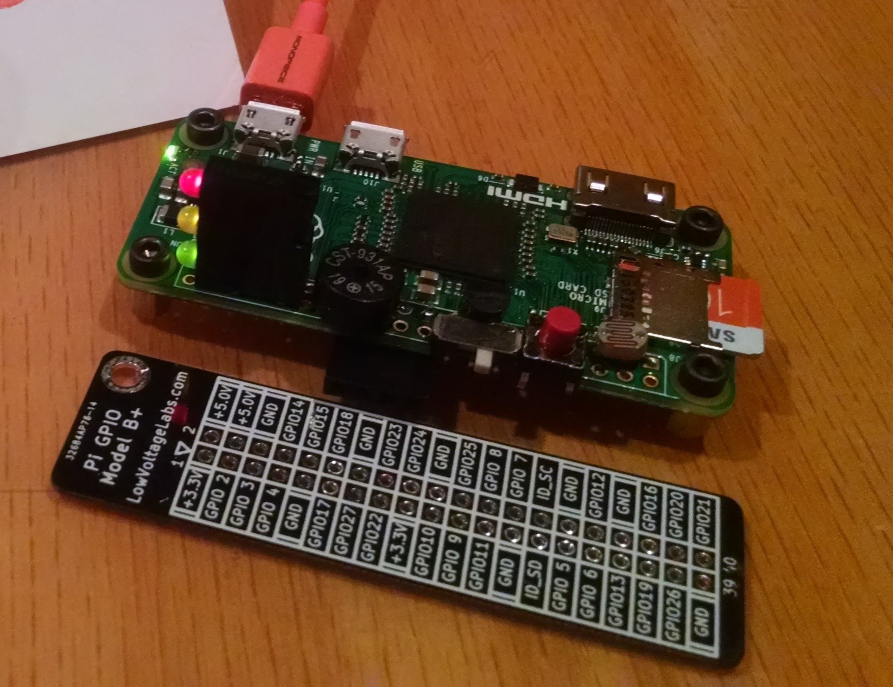
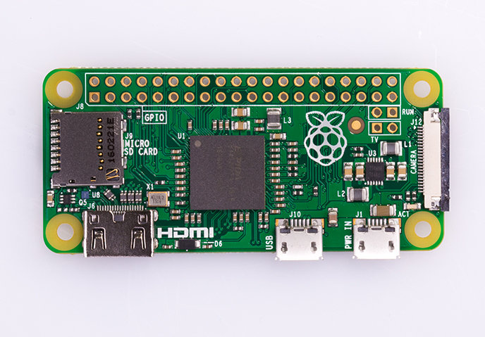
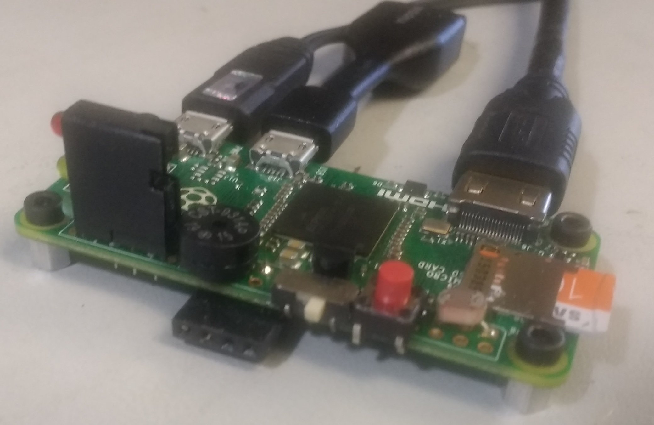
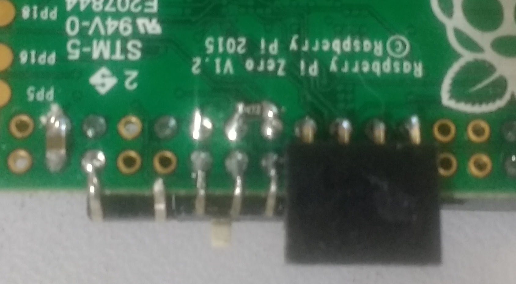
Raspberry Pi Zero $5
- 1GHz, Single-core CPU
- 512MB RAM
- Mini-HDMI port
- Micro-USB OTG port
- Micro-USB power
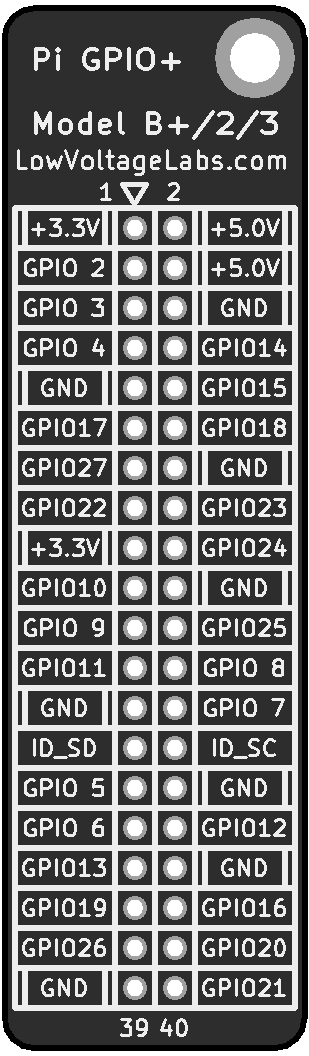
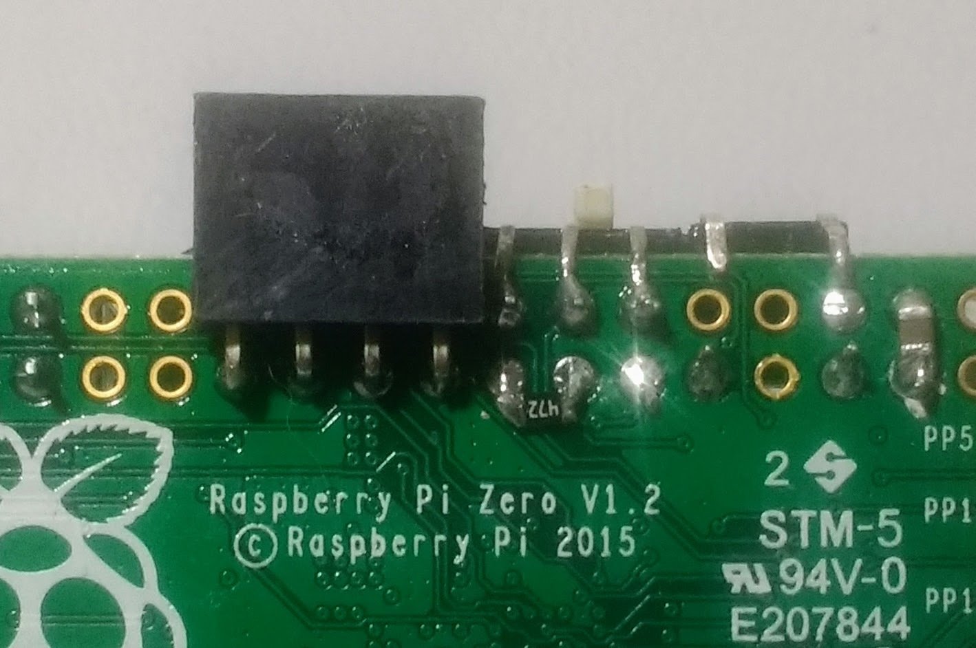
- HAT-compatible 40-pin header
- Composite video and reset headers
- CSI camera connector
Software setup
- Raspberry Pi Zero needs an SD card with an operating system installed on it
- Raspbian is the Raspberry Pi's foundation’s official supported operating system
- Purchase an SD card with it preinstalled
OR - Download and install yourself:
https://www.raspberrypi.org/downloads/raspbian/
Programming language
Python
- Popular in the Raspberry Pi community
- Lots of examples
- The Easy Guide to Programming a Raspberry Pi with Python
http://makezine.com/projects/program-raspberry-pi-with-python/ - Python Library gpiozero
https://gpiozero.readthedocs.io/
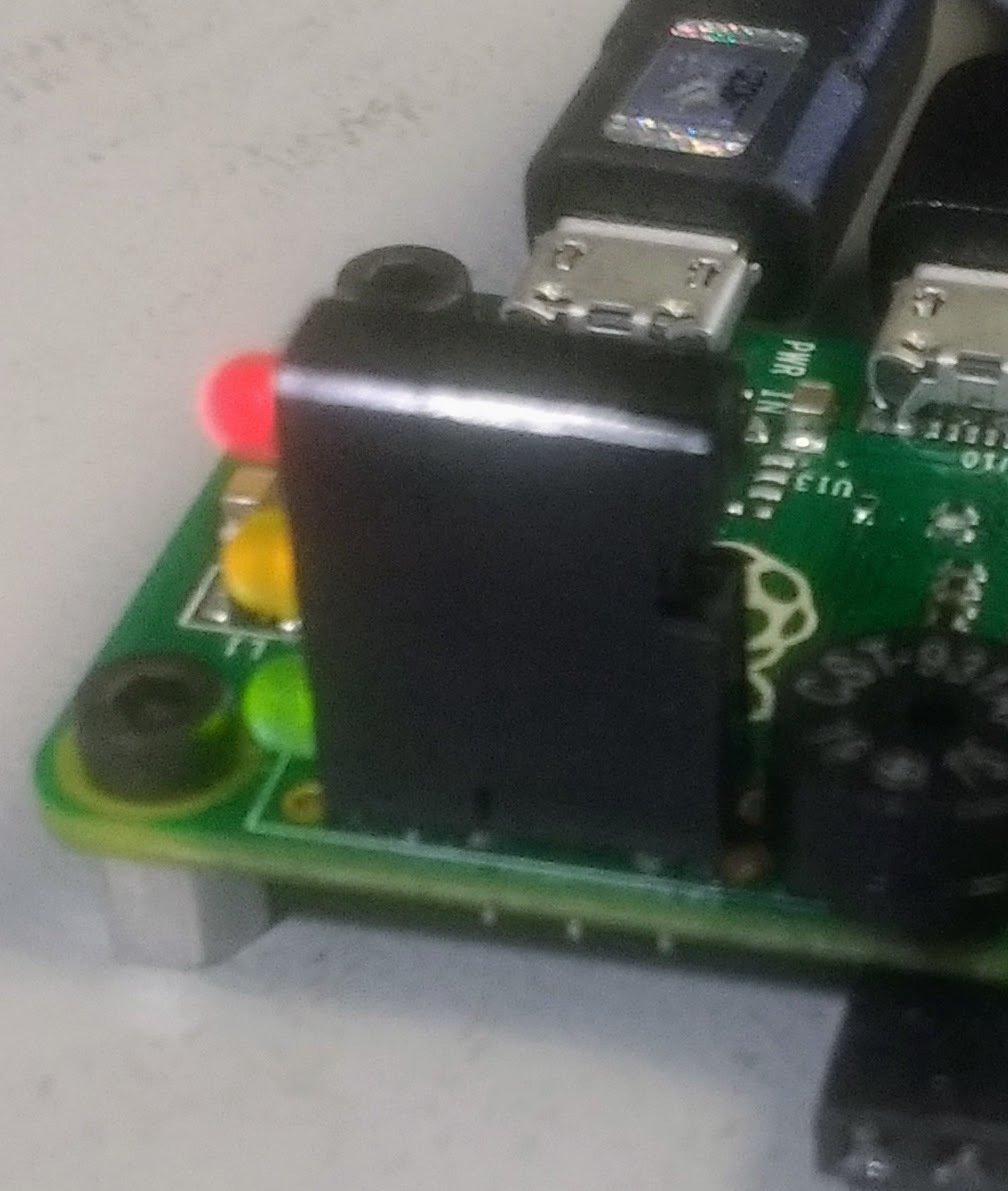
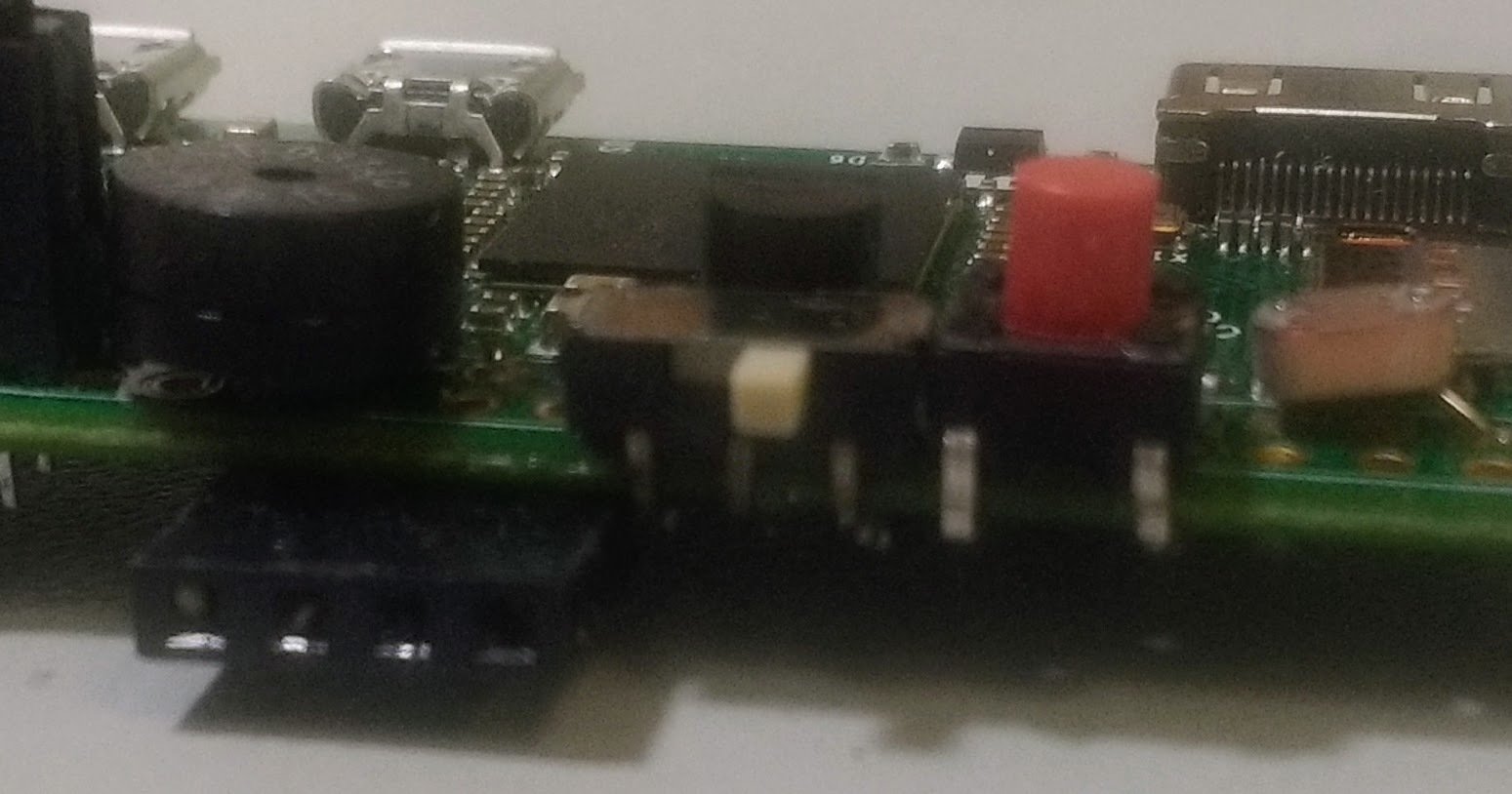
Output - LEDs
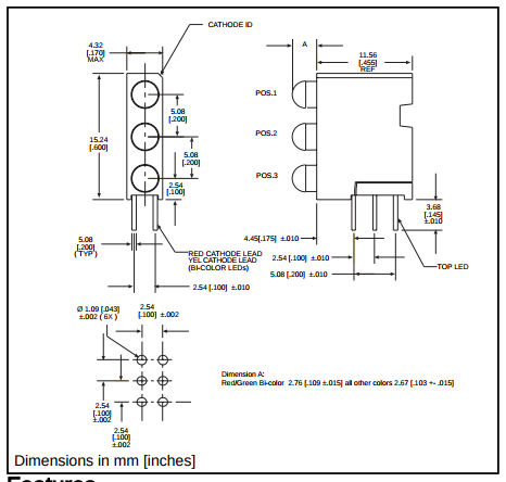
Dialight
P/N = 564-0300-132F
- Three LEDs
Red, Yellow, Green - 0.1" header spacing
- Built in resistors
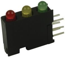
Dialight P/N = 564-0300-132F
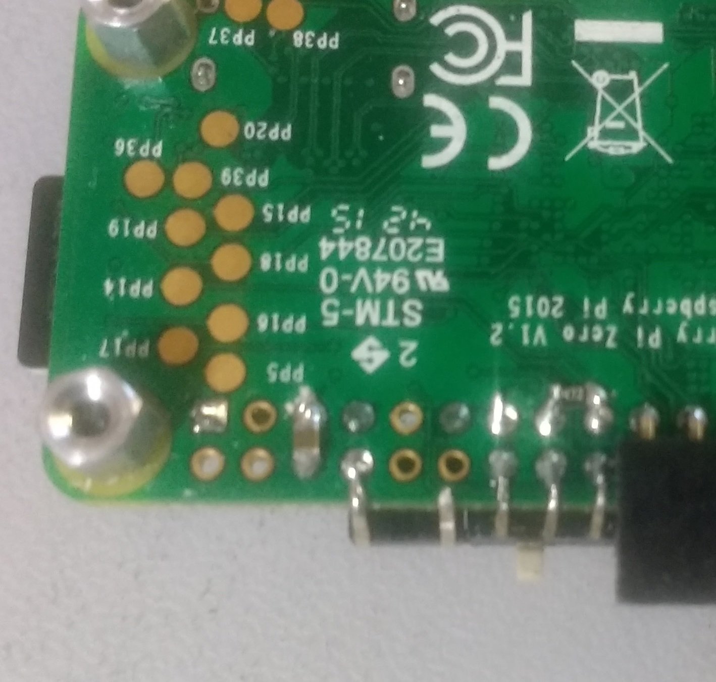
LED location
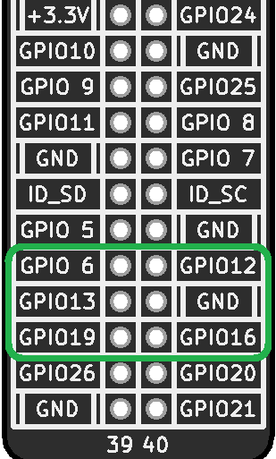
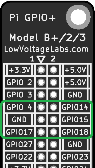
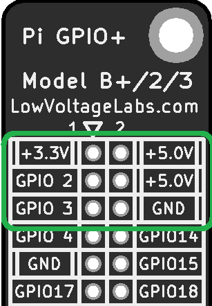
Use GPIO6, GPIO19 and GPIO26 to drive the LEDs
GPIO6 = Red
GPIO13 = Yellow
GPIO19 = Green
GPIO12 and GPIO16 drive to ground
LEDs
Turn on the LEDs
# Pi Zero Programming hardware

from gpiozero import *

# Set LED pins to ground
ground12 = OutputDevice(12,True,False)
ground16 = OutputDevice(16,True,False)

# Setup traffic lights
lights = TrafficLights(6,13,19)

# Turn on the lights
lights.on()

# Turn just the Red LED on
lights.red.on()
lights.amber.off()
lights.green.off()
Input - Push Button
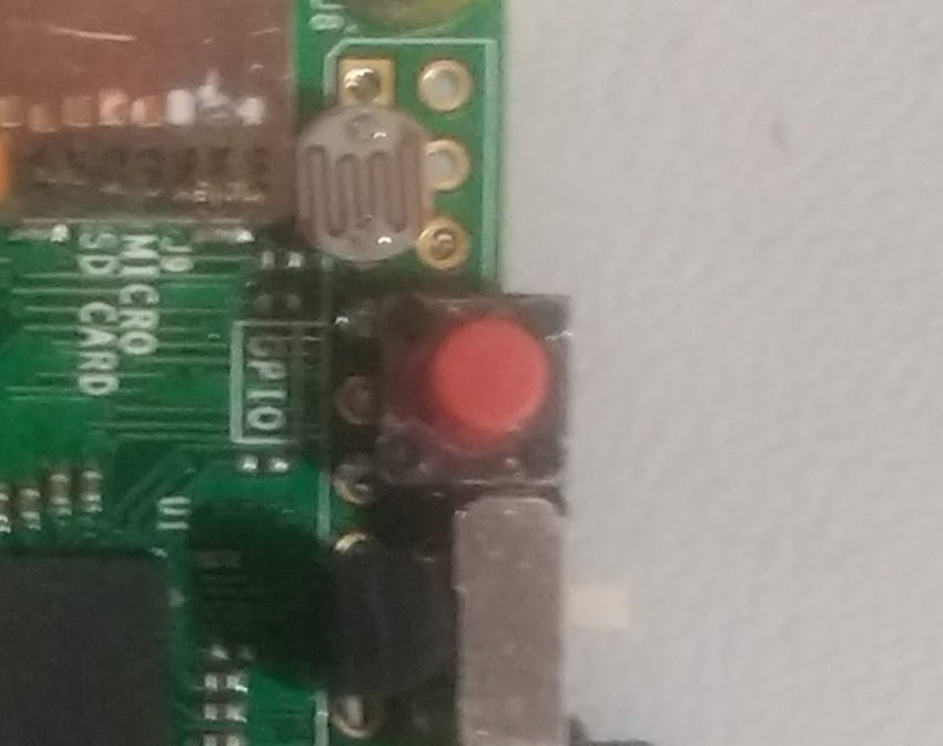
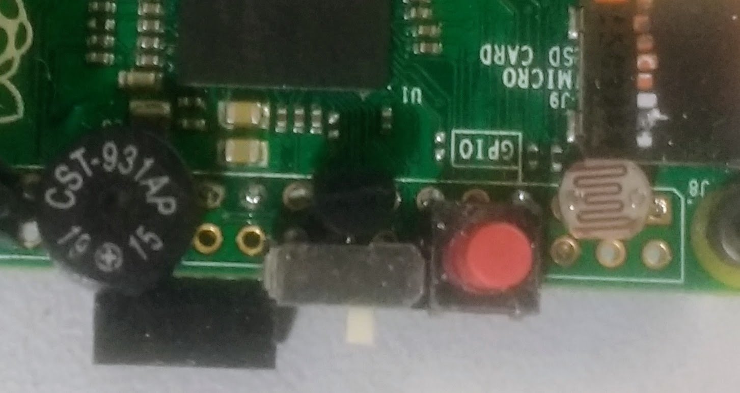
Manufacture = ALPS
P/N = SKHHBYA010
- Momentary push button
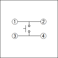
- SPST
- 0.1" spacing - sort of?
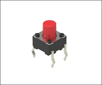
Installing the push button
Installing the push button
Top Bottom
Reading the push button
# Pi Zero Programming hardware

from gpiozero import *

#Set push button input to ground
ground17 = OutputDevice(17,True,False)

# setup the button press
def buttonpress():
    print("Button press")

#Setup the button press
button = Button(4)
button.when_pressed = buttonpress
Push button and LED
More inputs and outputs
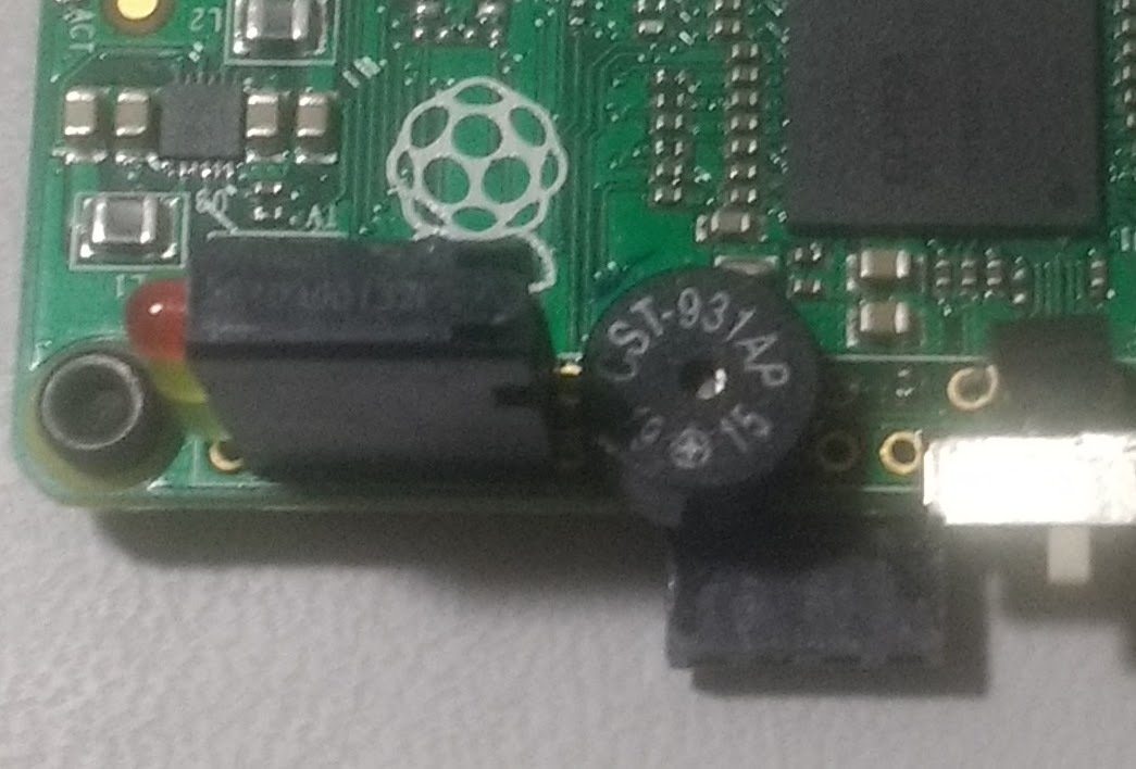
Output - Buzzer
Manufacture = CUI
P/N = CST-931AP
- Works from 3.3V
- 0.1" pin spacing
Input slide switch
Manufacture = Apem
P/N = MS22R
- Right angle
- 0.1" pin spacing
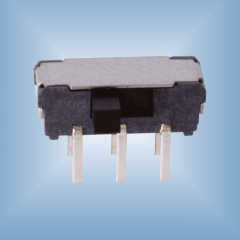
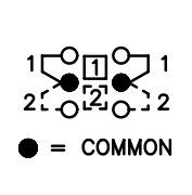
Input slide switch
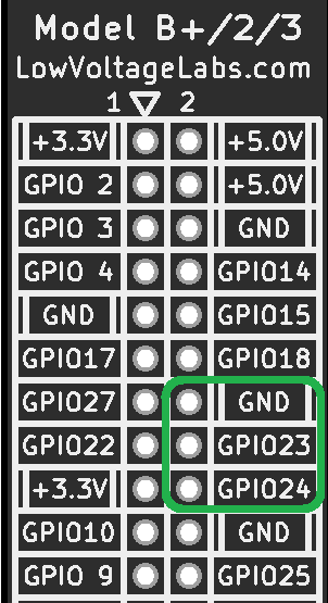
Reading the Slide Switch
# Pi Zero Programming hardware

from gpiozero import *

# Set slide switch to high
high24 = OutputDevice(24,True,True)

# Setup Input slide on pin 23
slide1 = InputDevice(23,True)

# Check slide switch
if slide1.is_active:
    print("slide switch right")
Input temperature
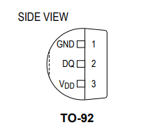
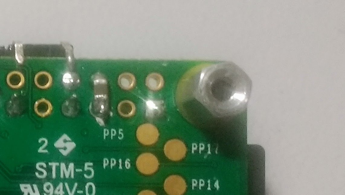
Manufacture = Maxim Integrated
P/N = MAX31820MCR+
- Only requires power and 1-wire interface
- TO-92 package
- Standard DS1820 part
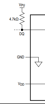
Input Temperature sensor
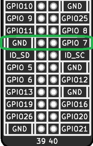
- GPIO27 will be ground
- GPIO22 data pin
- 4.7K resistor from GPIO22 to +3.3V
- Programming
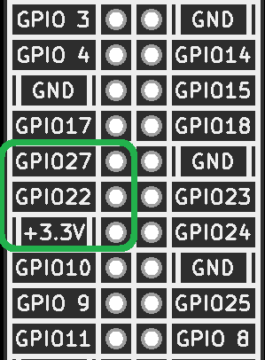
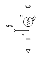
Input Photocell
- +3.3V to one side
- Other side to GPIO3
- 0.1uF capacitor
GPIO3 to GND
Photocell Programming
- Set GPIO3 to output and low
- Switch GPIO3 to an input
- Measure time before GPIO3 input is high
Part Prices
| Part | Qty = 1 price | Qty = 25 price |
|---|---|---|
| 3 stack LEDs | $3.28 | $2.15 |
| Push button | $0.15 | $0.15 |
| Buzzer | $1.34 | $0.93 |
| Slide switch | $0.89 | $0.84 |
| Temperature sensor | $1.30 | $1.24 |
| Photo sensor | $0.95 | $0.86 |
| Total = | $7.91 | $6.17 |
Questions?
See me for a free
GPIO Plus reference board
Eric Thompson
@LowVoltageLabs