

Enthusiast
Wireless transmission through Rf-Module
Members-
Abhishek Kumar (2013ecs07)
Aman kumar (2013ecs13)
Manoj Kumar (2013ecs33)
Shyam Tayal (2013ecs47

Wirelessly control a bulb.
Machine hai sir
Summary
This circuit utilizes the RF module (Tx/Rx) for making a wireless remote, which could be used to drive an output from a distant place. RF module, as the name suggests, uses radio frequency to send signals. These signals are transmitted at a particular frequency and a baud rate. A receiver can receive these signals only if it is configured for that frequency.
A four channel encoder/decoder pair has also been used in this system. The input signals, at the transmitter side, are taken through four switches while the outputs are monitored on a set of four LEDs corresponding to each input switch. The circuit can be used for designing Remote Appliance Control system. The outputs from the receiver can drive corresponding relays connected to any household appliance.
Title Text
Subtitle
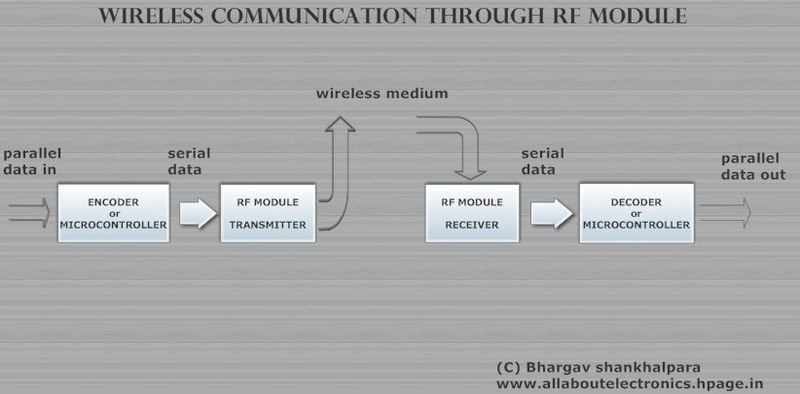
Block Diagram of Rf-Module
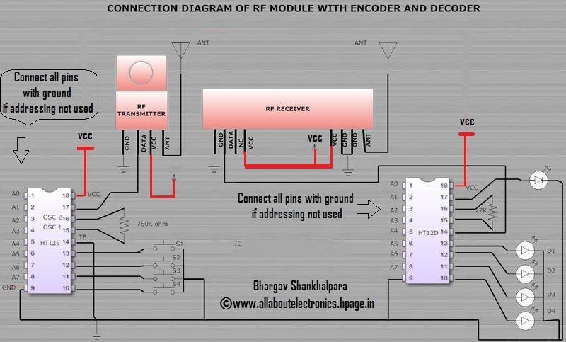
Circuit Diagram
Working And Description
- The transmitter module takes serial input and transmits these signals through RF.
- The transmitted signals are received by the receiver module placed away from the source of transmission.
- Here HT12E & HT12D have been used as encoder and
decoder respectively
- The encoder converts the parallel inputs (from the remote switches) into serial set of signals.
- The decoder is used after the RF receiver to decode the serial format and retrieve the original signals as outputs
- Encoder IC (HT12E) receives parallel data in the form of address bits and control bits.
- ............................................................ and the story continues.
Components
-
HT12D DECODER
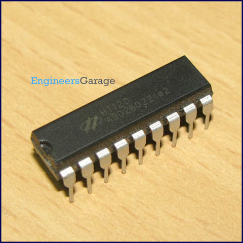
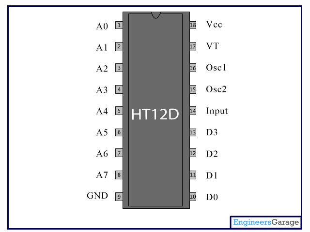
HT12D converts the serial input into parallel outputs. It decodes the serial addresses and data received by, say,
an RF receiver, into parallel data and sends them to output data pins. The serial input data is compared with the local addrs
three times continuously. The input data code is decoded when no error or unmatched codes are found. A valid
transmission in indicated by a high signal at VT pin.
2. HT12E ENCODER
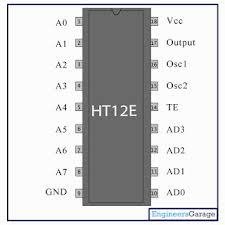
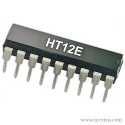
HT12E converts the parallel inputs into serial output. It encodes the 12 bit parallel data into serial for transmission through an RF transmitter. These 12 bits are divided into 8 address bits and 4 data bits. When a trigger signal is received on TE pin, the programmed addresses/data are transmitted together with the header bits via an RF or an infrared transmission medium.
3. Rf-Module
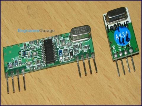
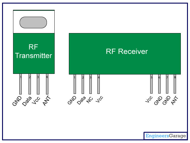
RF transmitter receives serial data and transmits it wirelessly through RF through its antenna connected at pin4
The encoder is used for encoding parallel data
for transmission feed while reception is decoded by a decoder

A typical morning Hostel scene :P
still wondering about our project?????
Project++
1. Increasing the range.
2. Adding more circuitry to it eg. Mobile connection etc.
3. Four appliances.
and much more........


Any questions?

Text
I hope not..
Because !!!!!!!!!!!!!!!!!!!!!!!!