Processor Fundamentals
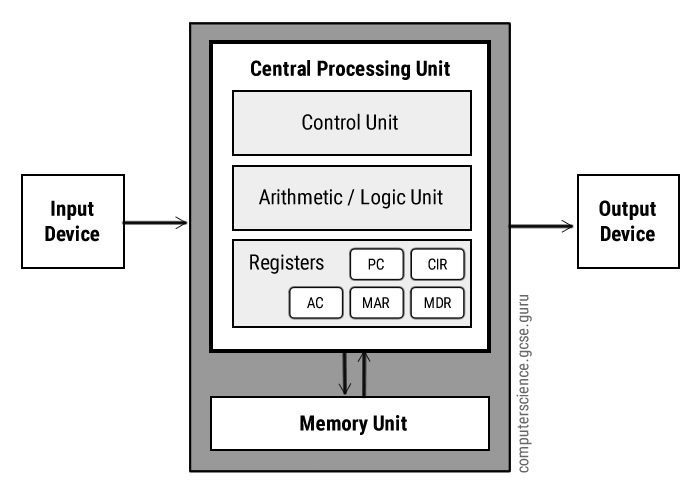
Von Neumann Model
- Modern Computer system architecture
- Stored Program: Computer Program and data are stored in main memory rather than hard-wired in hardware
- The CPU consists of:
- Registers
- Control Unit (CU)
- Arithmetic Logic Unit (ALU)
Run the "Addition" example in LMC, and write down the functions of:
- Arithmetic Unit
- Program Counter
- Instruction Register
- Address Register
- Accumulator
Registers
- Storage unit within the processor
- Fastest memory in a computer system
- Very small in size (each maybe a few bytes)
-
General purpose registers
- store data values from main memory or results of processing
- can be used by programmers
- Special purpose registers
| Registers | Equiv. in LMC* | Functions |
|---|---|---|
| Accumulator | Accumulator | General purpose, store value before and after execution of an instruction |
| Program Counter (PC) | PC | Holds the (memory) address of the next instruction to be fetched |
| Memory Data Register (MDR) | Stored the data value fetched from the memory, temporarily | |
| Memory Address Register (MAR) | Address Register | Stored the address of the memory that is about to be used by a program instruction |
| Current Instruction Register (CIR) | Instruction Register | Stored the currently executing instruction |
| Index Register (IX) | Stores a number which will be used to change an address value | |
| Status Register (SR) | Contains "Flags" which is represented by individual bits, that show the current status of the arithmetic operation. e.g. C - Carry V - Overflow N - Negative |
* https://peterhigginson.co.uk/LMC/
Buses
- Connects components within computer system
- Including:
- Address Bus
- Carries address to memory, for identifying a location in the main memory
- Data Bus
- Carries data from main memory to processor, input and output devices
- Control Bus
- Carry type of control signal will occupy one wire(line) in the control bus
- e.g. there will be a wire for "interrupt"
- e.g. another wire will represent memory write completed etc.
- Address Bus
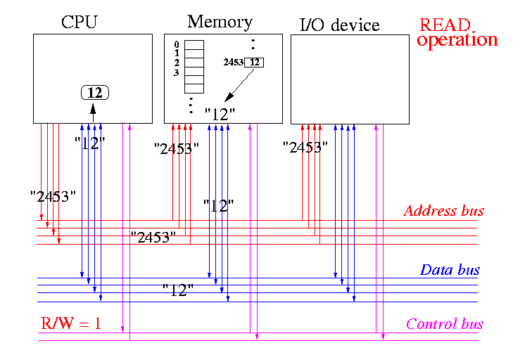
Diagram showing some buses with wires in a computer system
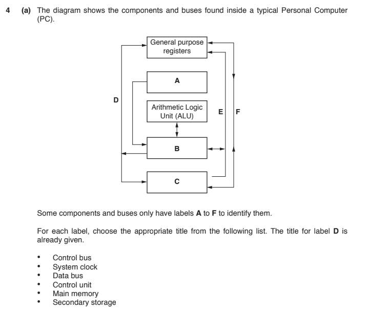
w17/qp13/4
Interrupt
- A signal to the processor generated by hardware or software
- to flag that some event has occurred
- Carried in the Control bus - Each interrupt will occupy one wire in the bus
- e.g.
- When there's Keyboard input
- Printer sends message when it's out of paper
- CPU will run some code to handle the event, usually pausing the current task
- Resume the task once interrupt is handled
Performance of a PC
- The "speed" of a computer is determined by many factors
- Some of those are:
- Clock speed
- Bus Width
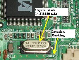
Clock speed
- The CPU will time it's operation with a "clock", which "ticks" in a set period of time
- e.g. modern desktop CPU is running at about 2GHz -> 2 Billion ticks per second
- Each operation will require a certain clock cycle to complete it
- Note the clock cycle required is different for different types of CPU, but for the same CPU architecture, the clock cycle required are fixed
- So one way to determine speed of CPU is the clock speed
Bus Width
- A Bus contains a number of physical wires
- Parallel data transmission: Each wire carries one bit at the same time
- e.g. If a CPU has 32-bit data bus and 16-bit address bus
- The largest data each time it can transfer is 2^32
- That also means the largest memory block it can address is 2^16
- Assume 1 block is 1 byte, how large is the main memory?
Fetch-execute cycle
| Remark | Stage | Register transfer notation |
|---|---|---|
| Fetch instruction | Program Counter (PC) loaded with address of next instruction | |
| Content of PC are copied to MAR | MAR <- [PC] | |
| Content of PC increased by 1 | PC <- [PC] + 1 | |
| Address given by MAR is located and content from main memory copied to MDR | MDR <- [ [MAR] ] | |
| Content of MDR are copied to CIR | CIR <- [MDR] | |
| Decode instruction | The opcode and operand are identified | |
| Execute instruction | ||
| Repeat the cycle if no interrupt |
Refer p.87 for the flowchart, also LMC to understand more on this
Processor instructions
- Machine code is the instruction that directly decoded by CPU, and denotes as binary values
- Each machine code can break into Opcode (what operation) and Operand
- Assembly Language translates (almost) 1-to-1 machine code by Assembler
Assembly
LDM #33
Machine Code
0000 0001 0010 0001
Assembler
Opcode
0000 0001
Operand
0010 0001
Decoded instruction
Modes of addressing
| Addressing Mode | Operand | Example |
|---|---|---|
| Immediate | The operand is the actual number used | LDM #13 Load Number 13 to accumulator |
| Direct | Operand is the address of the value |
LDD 56 Load the content in Address 56 into accumulator, that means, so accumulator will have 89 in this case |
| Indirect | Operand is the address of the address of the content |
LDI 55 The content in Address 55 will be used as the address for the actual content, thus, accumulator will have 135 |
| Indexed | Operand is added to the value of index register (IX) and resulted the address of the value needed |
LDX 51 and assume IX is 2 So the Accumulator will load the value from 53, which is 172 in this case |
| Address | Content |
|---|---|
| 51 | 54 |
| 52 | 135 |
| 53 | 172 |
| 54 | 201 |
| 55 | 52 |
| 56 | 89 |
Absolute vs Symbolic addressing
- All addressing values in the machine code is the actual address number
- e.g. LDD 30 will load the data in address "30"
- We can use "symbol" to represent a physical address of the location, e.g. LDD value
Then the assembler will calculate the offset of this symbol from the start of the program and replace with actual address
Directives
- Code inside assembly file, but not actual program instruction
- Directive is instruction to the assembler and linker
- e.g.
- ORG 100 - Tell the assembler the program code starts from address 100, instead of 0
- INCLUDE "FILE.LIB" - Include extra file in the program
Macros
- Macro is similar to "procedure" where code can be reused with different supply parameters
;Define a macro called "NameOfMacro"
;Note the keyword MACRO itself is directive
MACRO NameOfMacro
    <instructions>
END MACRO
;Calling macro
NameOfMacro
Assembler
- Assembler "translates" assembly code into executable machine code
- Two-pass assembler:
- first pass
- assign address to all statements in the program
- Address of symbolic labels (e.g. variable) are stored
- second pass
- translate opcode and operands
- first pass
First pass
- Uses a Symbol table to store name of symbols and their respective absolute address
- Codes are parsed line after line, and the symbol table is updated accordingly
- Label will be added / updated in table with the address of it
- Operand using labels will be added to table with unknown address
- Link to the simulator:
https://replit.com/@andytsuiacm/2-pass-assembler
Second Pass
- Opcode will be translated into machine code using the Operation code table
- Operand with address label (symbolic link) will be translated to absolute address using the Symbol table done in the first pass
Bit Manipulations
- Bullet One
- Bullet Two
- Bullet Three