Graphics Programming Virtual Meetup


Discord

Tiny Renderer
Lesson 4-5
Perspective projection
and Moving the Camera
Tutorial link:
https://github.com/ssloy/tinyrenderer/wiki/Lesson-4-Perspective-projection
My Code:
https://github.com/cdgiessen/TinyRenderer
Lesson 4:
Perspective Projection
Start with 2D
Linear Transformations
matrix vector multiplication
"Identity' matrix does not change anything
Altering the diagonal alters the scale

Non-diagonal non-zero values create "sheer"
multiple sheers combined together create rotation
A rotation matrix can be written directly using trigonometry
Note: Matrix multiplication is not communicative

2D Affine transformations
Scale & rotation do not change the origin
Translation can be achieved by simple addition
But this doesn't combine well, each translation must be stored separately from the rotation and scale
Homogeneous coordinates
Instead of using 2x2 matrices, use 3x3, but make the last row (0, 0, 1)
Then make any 2d vector a 3d vector but with the last element set to 1
This works because we embed 2D into 3D
Our 2D space is on the plane z=1 in the 3D space
We perform a linear 3D transformation then project it onto the 2D plane
Projecting 3D onto 2D is simple, divide by the 3D component
Composing transformations
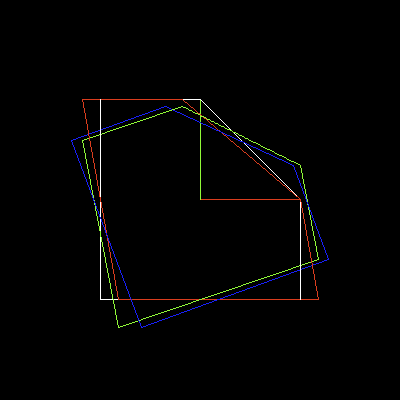
We want to rotate something other than the origin
First, translate it to the origin before rotating, then translate it back
Otherwise its a rotation about point (x, y)
What happens if we don't have (0,0,1) in the bottom row?

Remember the y-buffer exercise from the previous chapter
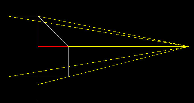
We will do the same thing but projecting onto a vertical line
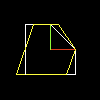
Picture a camera at point (5, 0)
To project it, trace lines from the camera to the points of our shape
Then project these onto the 'screen', a vertical column
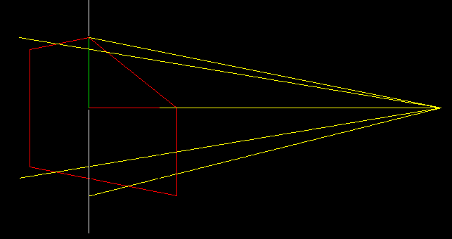
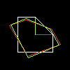
Now replace the object with the transformed one, not touching the yellow lines
Now let us make it

Do the same thing as 2D but add another dimention
Retro-projection for 4D onto 3D is:
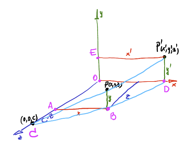
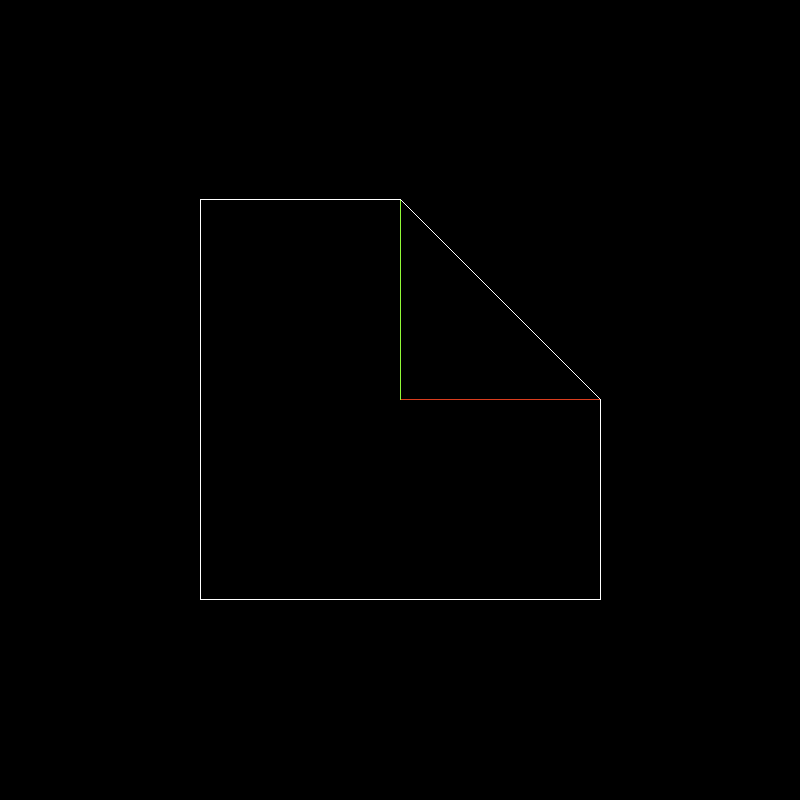
3D illustration of previous 2D projection
X & Y's change when projecting from the 3d space onto the 2d plane (z = 0)
Z isn't altered, it doesn't appear on a 2D image output
Lesson 5:
Moving the camera
Change of basis
Point P in basis O
Now to transform P into a point in O'
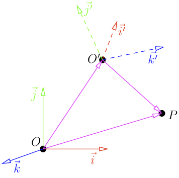
Substitute (i', j', k') with M
And then we can change coordinates basis
Previous lessons had the camera only located on the Z axis
We want to draw the scene so that the 'eye' could be at any point
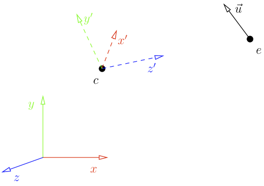
Look at function
void lookat(Vec3f eye, Vec3f center, Vec3f up) {
    Vec3f z = (eye-center).normalize();
    Vec3f x = cross(up,z).normalize();
    Vec3f y = cross(z,x).normalize();
    Matrix Minv = Matrix::identity();
    Matrix Tr   = Matrix::identity();
    for (int i=0; i<3; i++) {
        Minv[0][i] = x[i];
        Minv[1][i] = y[i];
        Minv[2][i] = z[i];
        Tr[i][3] = -center[i];
    }
    ModelView = Minv*Tr;
}
Viewport
screen_coords[j] = Vec2i((v.x+1.)*width/2.,(v.y+1.)*height/2.);
Turns a [-1, 1] square into coordinates [0, width], [0, height]
Rewrite in a matrix
Matrix viewport(int x, int y, int w, int h) {
    Matrix m = Matrix::identity(4);
    m[0][3] = x+w/2.f;
    m[1][3] = y+h/2.f;
    m[2][3] = depth/2.f;

    m[0][0] = w/2.f;
    m[1][1] = h/2.f;
    m[2][2] = depth/2.f;
    return m;
}Combine the matrices all together
Viewport * Projection * View * Model * v

Vec3f v = model->vert(face[j]);
screen_coords[j] =  Vec3f(ViewPort*Projection*ModelView*Matrix(v));
Model is the 'location' of the object we are drawing
Currently (0,0,0)
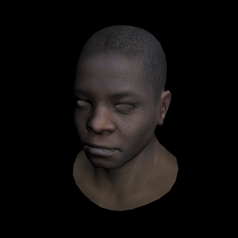
Result
Transformation of normal vectors
Can't scale normal vectors non-uniformly
Causes noticeable distortion
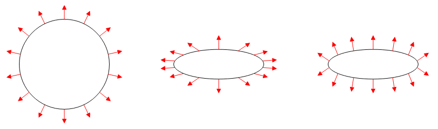
Not necessary for current lesson, but will need to be tackled for proper lighting.
Solution is to multiply the normals by the inverse transpose of the transformation matrix