Data Communications and Networking
Network Models
RS Maniaol
Network
combination of hardware and software that sends data from one location to another
Hardware consists of physical equipment that carries signals
Software consists of instruction sets that make possible the services that we expect from a network
OSI Model
International Standards Organization (ISO) introduced the Open Systems Interconnection model in the late 1970s
OSI model ISO/IEC 7498-1
Open system – a set of protocols that allows any two different systems to communicate regardless of the underlying architecture
OSI is not a protocol; it is a model for understanding and designing a network architecture that is flexible, robust, and interoperable
OSI Layers
Physical
Data Link
Network
Transport
Session
Presentation
Application
1
2
3
4
5
6
7


Interaction between Layers
Application
Application
Presentation
Presentation
Session
Session
Transport

Transport
Network
Network
Data Link
2 - 1 Interface
Physical
Physical
Data Link
3 - 2 Interface
4 - 3 Interface
5 - 4 Interface
6 - 5 Interface
7 - 6 Interface
Physical
Physical
Data Link
Data Link
Network
Network
7 - 6 Interface
6 - 5 Interface
5 - 4 Interface
4 - 3 Interface
3 - 2 Interface
3 - 2 Interface
3 - 2 Interface
2 - 1 Interface
2 - 1 Interface
2 - 1 Interface
Encapsulation
D7
H7

D6
H6
D5
D7

H7
H5
H4
H3
H2
H1
H6
H5
H4
H3
H2
H1
D6
D5
D4
D4
D3
D3
D2
D1
D2
D1
Physical Layer
Defines the connector and interface specifications as well as the medium (cable) requirements
Electrical, mechanical, functional and procedural specifications are provided for sending a bit stream on a computer network
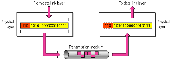
Physical Layer
Physical characteristics of interfaces and medium
Representation of bits - encoding
Data rate - number of bits sent each second
Synchronization of bits - timing
Line configuration – point-to-point, multipoint
Physical topology – bus, star, ring, mesh, hybrid
Transmission mode – simplex, half-duplex, duplex
Components of a Physical Layer
- Cabling system components
- Adapters that connect media to physical interfaces
- Connector design and pin assignments
- Hub, repeater and patch panel specifications
- Wireless system components
- Parallel SCSI
- Network Interface Card (NIC)
Data Link Layer
Transforms the physical layer to a reliable link
Makes the physical layer appear error-free to the upper layer
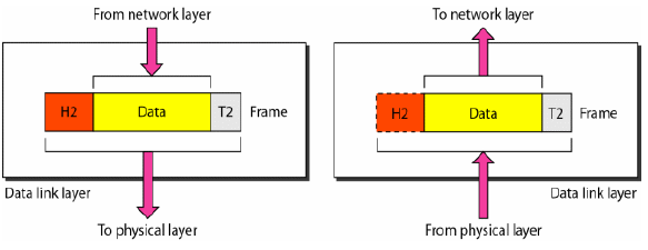
Data Link Layer
Framing – defining frames
Physical addressing – defines sender/receiver
Flow control – prevents overwhelming the receiver
Error control – detect and retransmit damaged or lost frames, use of trailers
Access control – defines which device has control over the link when it is shared by devices
Components that function at Layer 2
- NIC drivers
- Ethernet and Token Ring Switches
- Bridges
Hop to Hop Delivery
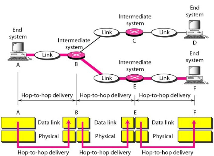
Network Layer
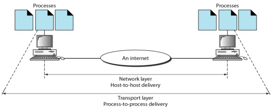
Source-to-destination delivery of packets, possibly across multiple networks
No need for network layer if two systems are connected to the same link
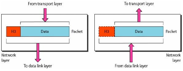
Network Layer
Logical addressing – distinguish source and destination systems if packets pass network boundary
Routing – makes possible the delivery of packets in internetworks, connecting devices are called routers and switches
Source to Destination Delivery

Transport Layer
Responsible for process-to-process delivery
Ensures that the whole message arrives intact and in order
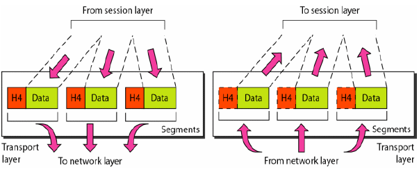
Transport Layer
Service-point addressing – several programs can use the network, uses ports
Segmentation and reassembly – message divided into transmittable segments (uses sequence numbers)
Connection control – maybe connectionless or connection-oriented
Flow control – end-to-end flow control rather than a single link
Error control – process-to-process flow control rather than single link
Process to Process Delivery
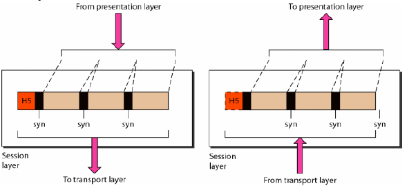
Session Layer
Network dialog controller
Establishes, maintains, and synchronizes interactions among communicating systems
Dialog control – dialog between two systems
Synchronization – add checkpoints
Presentation Layer
Concerned with the syntax and semantics of the information exchanged between two systems
Translation – apply encoding schemes
Encryption – provides privacy
Compression – reduce the number of bits contained in the information
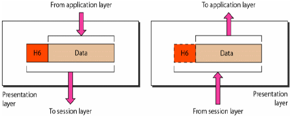
Application Layer
Enables the user (human or software) to access the network
Provides user interfaces and support services: email, remote file access and transfer, shared DBM, distributed information services
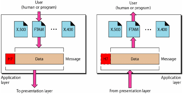
Application Layer
Network virtual terminal – software version of a software terminal
File transfer, access, and management – access files remotely
Mail services – email forwarding and storage
Directory services – distributed database sources
Sample Protocols at Layer 7
- HTTP – Hypertext Transfer Protocol
- FTP – File Transfer Protocol
- SMTP – Simple Mail Transfer Protocol
- POP3 – Post Office Protocol
- IMAP – Internet Message Access Protocol
- DNS – Domain Name Service
- Telnet
OSI Layers
Physical
Data Link
Network
Transport
Session
Presentation
Application
To transmit bits over a medium; to provide mechanical and electrical specifications
To organize bits into frames; to provide hop-to-hop delivery
To move packets from source to destination; to provide internetworking
To provide reliable process-to-process message delivery and error recovery
To establish, manage and terminate sessions
To translate, encrypt and compress data
To allow access to network resources
TCP/IP Protocol Suite
Developed prior to the OSI model
Originally defined as having four layers: host-to-network, internet, transport, application
DCN views it as having five layers: physical, data link, network, transport, application
Hierarchical protocol made up of interactive modules – upper-level protocol is supported by one or more lower-level protocols
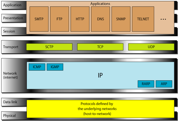
TCP/IP Protocol Suite
TCP/IP: Physical and Data Link
Does not define any specific protocol
Supports all standard and proprietary protocols
May be LAN or WAN
TCP/IP: Internetwork Layer
Internet Protocol (IP)
- unreliable and connectionless, best-effort delivery
- Packets are called datagrams
- Can follow different paths and arrive out of sequence or be duplicated
- Limited functionality is not a weakness: provides bare-bones transmission functions (efficiency)
TCP/IP: Internetwork Layer
- Associates a logical address with a physical address
- Used to find the physical address of the node when its Internet address is known
Address Resolution Protocol (ARP)
Reverse Address Resolution Protocol (RARP)
- Used to find the Internet address given the physical address
- Used when a computer is connected to a network for the first time or when a diskless computer is booted
TCP/IP: Internetwork Layer
Internet Control Message Protocol (ICMP)
- Used by hosts and gateways to send notification of datagram problems back to sender
- Sends query and reporting messages
Internet Group Message Protocol (IGMP)
- Facilitates simultaneous transmission of a message to a group of recipients
TCP/IP: Transport Layer
IP is host-to-host, UDP and TCP are process-to-process
User Datagram Protocol (UDP)
- Adds only port addresses, checksum error control, and length information
- Connectionless, unreliable
Transmission Control Protocol (TCP)
- Provides full transport-layer services
- Connection-oriented, reliable stream transport
- Streams are divided into segments with sequence numbers
TCP/IP: Transport Layer
Stream Control Transmission Protocol (SCTP)
- best of TCP and UDP
- message oriented like UDP
- ensures reliable, in-sequence transport of message like TCP
- VoIP
TCP/IP: Application Layer
Combined Session, Presentation, and Application layers in the OSI model
TCP/IP Addressing
Physical Layer
Data Link Layer
Network Layer
Transport Layer
Application Layer
Underlying
physical
network
IP and
other protocols
SCP TCP UDP
Processes
Physical Addresses
Logical Addresses
Port Addresses
Specific Addresses
Physical Addresses
Lowest-level address defined by a node's LAN or WAN
Size and format varies depending on network
Example: Ethernet uses 6-byte physical addresses written as 12 hexadecimal digits separated by a colon
68:a3:c4:ce:8c:e2
Physical Addresses
Organizationally Unique Identifier (OUI)
Dell: 00-14-22
Nortel: 00-04-DC
Cisco: 00-40-96
Belkin: 00-30-BD
Physical Addresses

Logical Addresses
Necessary for universal communications – internetworks
Internet (IP) address is 32 bits
No two publicly addressed and visible host on the Internet can have the same IP address
Logical Addresses
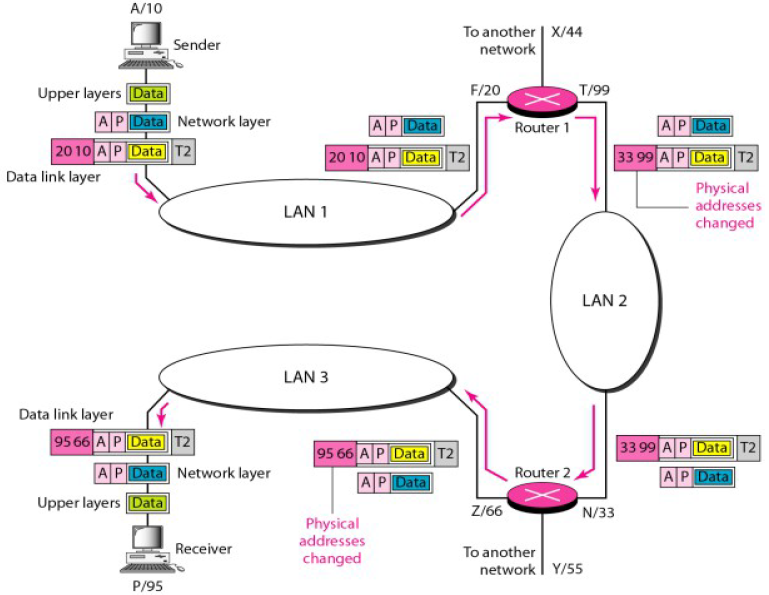
Logical Addresses
A/10

Data
A|P
10 | 20
T2

F/20
Data
A|P
Data
Upper Layers
Network Layer
Data Link Layer
LAN 1
T/99
10 | 20
A|P
Data
T2
A|P
Data
To another network
X/44
Router 1
Sender

Logical Addresses
F/20
A|P
A|P
Data
Data
T2
LAN 2
T/99

N/33
A|P
Data
Data
A|P
T2
Z/66
A|P
A|P
Data
Data
T2
T2
Data
A|P
66 | 95
10 | 20
99 | 33
99 | 33
A|P
Data
Router 1
Router 2

Logical Addresses
LAN 3

Z/66
P/95
Data
Data
Data
Data
A|P
A|P
A|P
A|P
66 | 95
66 | 95
T2
T2
Data
Receiver
Router 2
Note: To check your machine's physical and logical addresses, you could type these commands on your command line interface or terminal
Windows: ipconfig /all
Unix/Linux: ifconfig
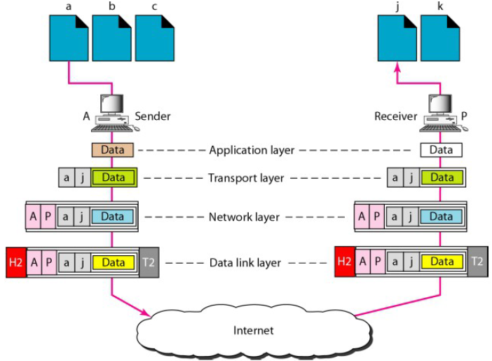
objective of Internet communication is a process communicating with another (peer) process running on a remote computer
Port Addresses
TCP/IP Port address – assigned to a process,16 bits
Port Addresses
| Protocol | TCP/UDP | Port Number |
|---|---|---|
| FTP | TCP | 20 (data) 21 (control) |
| SSH | TCP | 22 |
| DNS | TCP/UDP | 53 |
| DHCP | UDP | 67 (server) 68 (client) |
| HTTP | TCP | 80 |
| POP3 | TCP | 110 |
| NTP | UDP | 123 |
Port Addresses
Specific Addresses
User-friendly addresses
Example: email addresses, URL
Changed to corresponding port and logical addresses
References
- Forouzan, B.A. 2007. Data Communications and Networking, 4th Ed.McGraw-Hill, New York
- http://whatismyipaddress.com/mac-address