Lesson 2:
Camera and Lens Models
Contents
- Introduction
- Camera Coordinate Spaces
- Perspective Camera Model
- Other Camera Models
- Camera Lens Models
Introduction
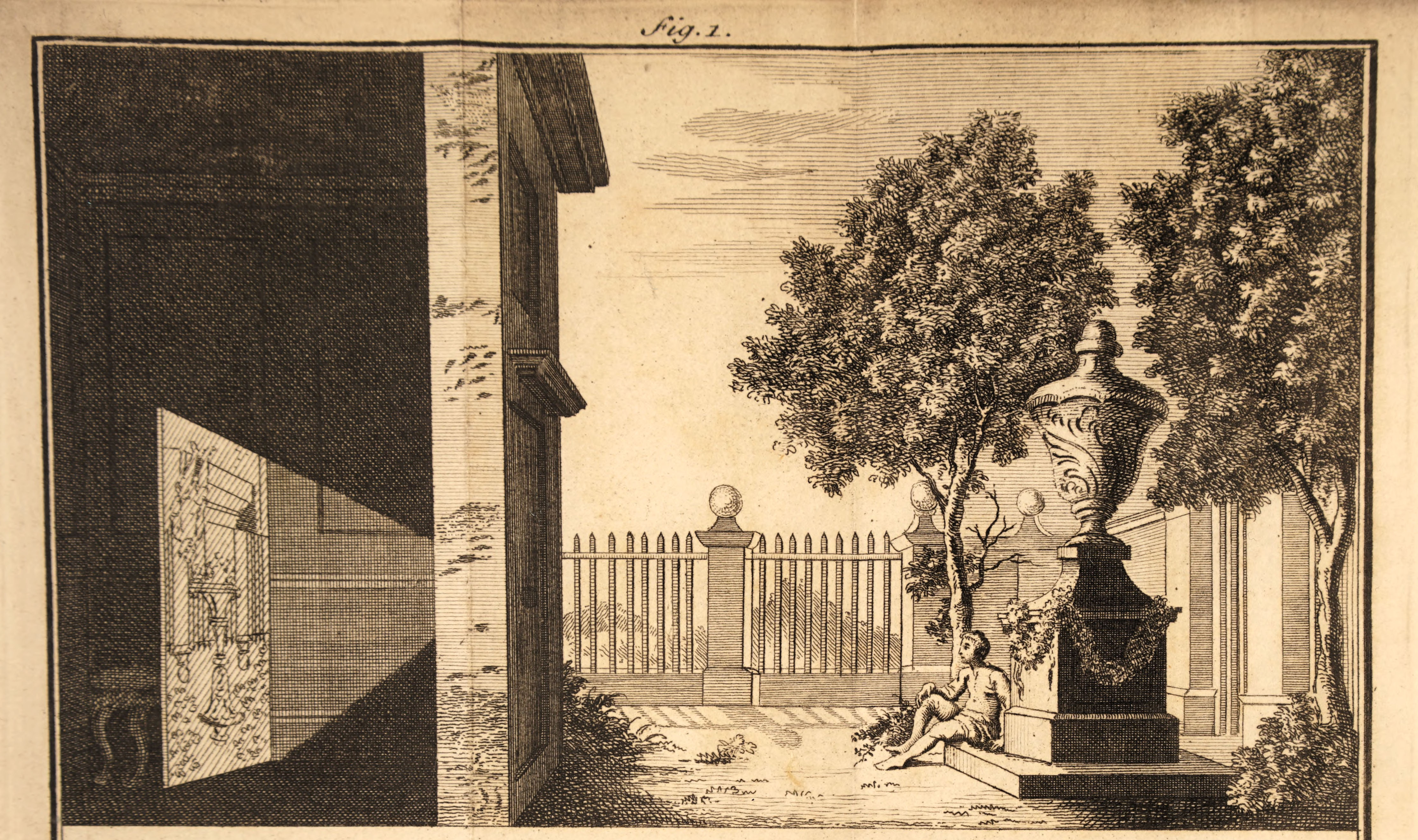
There are theories that occurrences of camera obscura effects (through tiny holes in tents or in screens of animal hide) inspired paleolithic cave paintings. It is also suggested that camera obscura projections could have played a role in Neolithic structures.
Camera obscura
aka pinhole camera
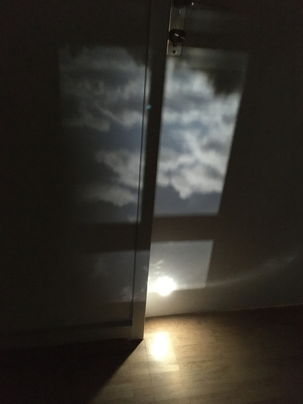
is the natural optical phenomenon that occurs when an image of a scene at the other side of a screen is projected through a small hole in that screen as a reversed and inverted image on a surface opposite to the opening.
(The surroundings of the projected image have to be relatively dark for the image to be clear, so many historical camera obscura experiments were performed in dark rooms)

Rays of light travel in straight lines and change when they are reflected and partly absorbed by an object, retaining information about the color and brightness of the surface of that object. A small enough opening in a screen only lets through rays that travel directly from different points in the scene on the other side, and these rays form an image of that scene when they are collected on a surface opposite from the opening.
The human eye works much like a camera obscura with an opening (pupil), a biconvex lens and a surface where the image is formed (retina).
Camera Obscuras today
... are opened to the public in form of museums or entertainment facilities, e.g. in Europe:
- Camera Obscura and museum "Prehistory of Film", Mülheim, Germany
- Camera Obscura, Tavira, Portugal
- Photographer's Gallery, London, England
- Camera Obscura, and World of Illusions, Edinburgh, Scotland
Pinhole Lenses
A recent Kickstarter project: world’s first multi-aperture pinhole lens for DSLRs


The Pinhole Camera
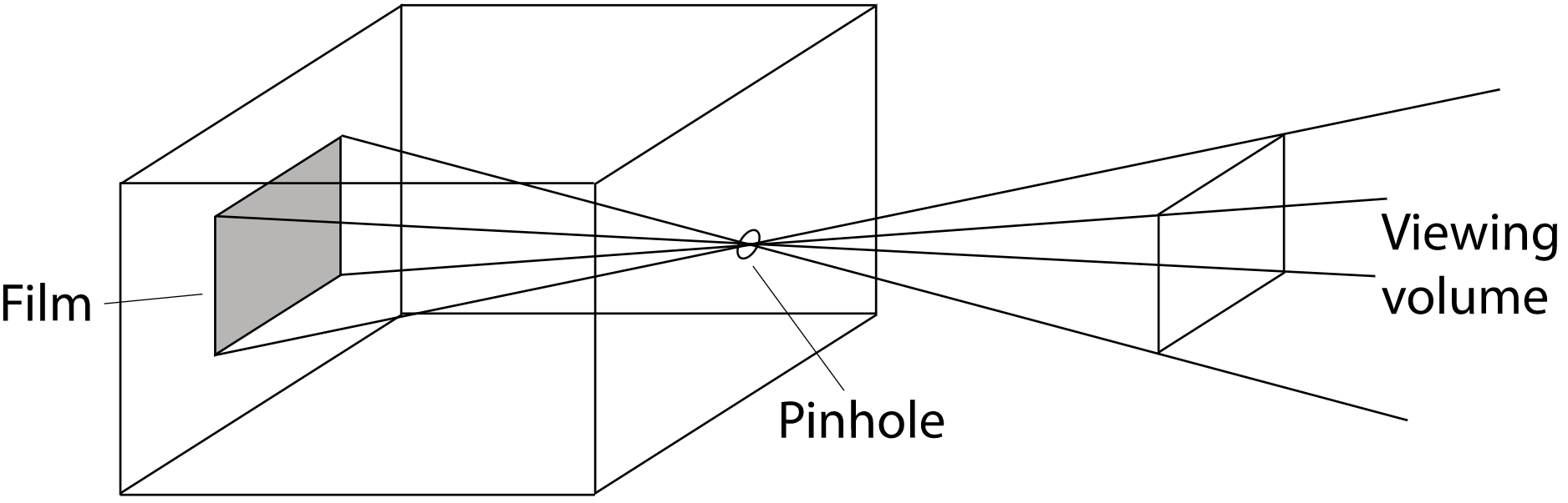
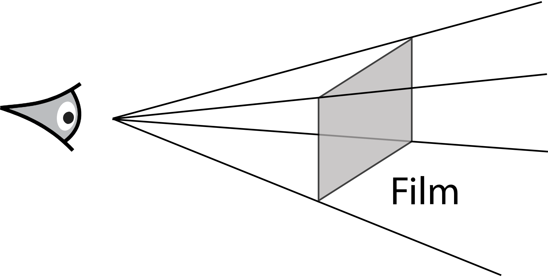
When we simulate a pinhole camera, we place the film in front of the hole at the near plane, and the hole is renamed the eye. This model is commonly used in Computer Graphics
Pinhole camera is a perspective camera by its nature.
... is one of the simplest devices for taking photographs. Pinhole cameras consist of a light-tight box with a tiny hole at one end. When the hole is uncovered, light enters this hole and falls on a piece of photographic paper that is affixed to the other end of the box. Despite its simplicity, this kind of camera is still used today, frequently for artistic purposes. Very long exposure times are necessary to get enough light on the film to form an image.
This model is easy to describe and simulate, but it neglects important effects that lenses have on light passing through them that occur with real cameras. For example, everything rendered with a pinhole camera is in sharp focus—a state of affairs not possible with real lens systems. Such images often look computer generated.
Motivation
Need to project 3D world onto 2D screen
Based on:
- Positioning of objects in 3D space
- Positioning of light sources in 3D space
- Positioning of the virtual camera in 3D space
Coordinate Systems
Object (local) coordinate system | 3D
This is the coordinate system in which geometric primitives are defined
(e.g., spheres are defined to be centered at the origin of their object coordinate system)
World (global) coordinate system | 3D
While each primitive may have its own object coordinate system, all objects in the scene are placed in relation to a single world coordinate system. Each primitive has an object-to-world transformation that determines where it is located in world space.
Camera coordinate system | 3D
A camera is placed in the scene at some world space point with a particular viewing direction and orientation. Thus camera defines a new coordinate system with its origin at the camera’s location. The z axis of this coordinate system is mapped to the viewing direction, and the y axis is mapped to the up direction.
Screen coordinate system | 3D
Screen space is defined on the film plane. The camera projects objects in camera space onto the film plane; the parts inside the screen window are visible in the image that is generated. Depth z values in screen space range from 0 to 1, corresponding to points at the near and far clipping planes, respectively.
Normalized device coordinate (NDC) system | 2.5D
This is the coordinate system for the actual image being rendered. In x and y, this space ranges from (0, 0) to (1, 1), with (0, 0) being the upper-left corner of the image. Depth values are the same as in screen space.
Raster (screen) coordinate system | 2D
This is almost the same as NDC space, except the x and y coordinates range from (0, 0) to (resolution.x, resolution.y)
Model transformation
- Object-to-World coordinate system
- Typically an affine transformation
View transformation
- World-to-Camera coordinate system
- Typically an affine transformation
Coordinate Transformations
Projective transformation
- Camera-to-NDC coordinate system
- Parallel or perspective projection
- 3D to 2D: Preservation of depth in Z coordinate
Viewport transformation
- NDC-to-Raster coordinate system
Coordinate Transformations
Ray Parametrization
ray's origin
ray's direction vector
a parameter whose legal range is
We can obtain a point along the ray by specifying its parametric t value and evaluating the above equation
struct Ray
{
	Vec3f	org;	// Origin
	Vec3f	dir;	// Direction
	double	t;	// Current/maximum hit distance
}Extrinsic Parameters
Camera configuration
-
Sensor resolution
- Aspect Ratio
-
Focal length
- Opening angle
Intrinsic Parameters
Camera pose
- Position
- Direction
- Up-vector (not necessary orthogonal to the direction vector)
Perspective Camera Definition
Vec3f	m_pos;	// Origin (center of projection)
Vec3f	m_dir;	// Viewing direction
Vec3f	m_up;	// Up-vector
const Size  m_resolution;   // Image resolution in pixels
const float m_aspectRatio;  // Image aspect ratio
      float m_focus;        // The focal length
Perspective Camera Model
Raster: (0,0)
Raster: (res.x, res.y)
m_pos
m_up
m_dir
pixel: (x, y)
m_focus
Ray Initialization
We need to generate a ray, which origins at the camera's center of projection and passes through the desired pixel
ray.org = m_pos
ray.dir = ?
ray.t   = infinity
Perspective Camera Model
Raster: (0,0)
Raster: (res.x, res.y)
m_pos
zAxis
pixel: (x, y)
Camera Coordinate System
We need to define a new coordinate system where the z-axis is mapped to the viewing direction, and the y-axis is mapped to the up direction
zAxis = m_dir
xAxis = zAxis x m_up
yAxis = zAxis x xAxis
xAxis
yAxis
m_up
m_focus
Ray Initialization
We need to generate a ray, which origins at the camera's center of projection and passes through the desired pixel
ray.org = m_pos
ray.dir = ?
ray.t   = infinity
Perspective Camera Model
Raster: (0,0)
NDC: (0,0)
Screen: (-1, -1)
Raster: (res.x, res.y)
NDC: (1, 1)
Screen: (1, 1)
m_pos
zAxis
pixel: (sscx, sscy)
Raster to NDC to Screen
Next we need to transform pixel coordinates (x, y) from Raster Coordinates first to NDC and then to Screen Coordinates
ndcx = x / res.x
ndcy = y / res.y

sscx = 2 * ndcx - 1
sscy = 2 * ndcy - 1
xAxis
yAxis
m_focus
Ray Initialization
We need to generate a ray, which origins at the camera's center of projection and passes through the desired pixel
ray.org = m_pos
ray.dir = ?
ray.t   = infinity
Perspective Camera Model
Screen: (-1, -1)
Screen: (1, 1)
m_pos
zAxis
pixel: (sscx, sscy)
Track point P
P = m_pos
xAxis
yAxis
m_focus
m_focus
Ray Initialization
We need to generate a ray, which origins at the camera's center of projection and passes through the desired pixel
ray.org = m_pos
ray.dir = ?
ray.t   = infinity
Perspective Camera Model
Screen: (-1, -1)
Screen: (1, 1)
m_pos
zAxis
pixel: (sscx, sscy)
Track point P
P = m_pos + zAxis*m_focus
xAxis
yAxis
m_focus
m_focus
Ray Initialization
We need to generate a ray, which origins at the camera's center of projection and passes through the desired pixel
ray.org = m_pos
ray.dir = ?
ray.t   = infinity
Perspective Camera Model
Screen: (-1, -1)
Screen: (1, 1)
m_pos
zAxis
pixel: (sscx, sscy)
Track point P
P = m_pos + zAxis*m_focus + xAxis*sscx
xAxis
yAxis
m_focus
m_focus
Ray Initialization
We need to generate a ray, which origins at the camera's center of projection and passes through the desired pixel
ray.org = m_pos
ray.dir = ?
ray.t   = infinity
Perspective Camera Model
Screen: (-1, -1)
Screen: (1, 1)
m_pos
zAxis
pixel: (sscx, sscy)
Ray Initialization
We need to generate a ray, which origins at the camera's center of projection and passes through the desired pixel
ray.org = m_pos
ray.dir = zAxis*m_focus + xAxis*sscx + yAxis*sscy
ray.t   = infinity
Track point P
P = m_pos + zAxis*m_focus + xAxis*sscx + yAxis*sscy
xAxis
yAxis
m_focus
m_focus
Ray Direction
ray.dir = P - m_pos
Perspective Camera Model
// x and y are pixel coordinates in raster coordinate system
void CCameraPerspective::InitRay(Ray& ray, int x, int y)
{
    Size resolution = getResolution();

    // Normalized device coordinates in [0, 1]
    float ndcx = static_cast<float>(x) / resolution.width;
    float ndcy = static_cast<float>(y) / resolution.height;

    // Screen-space coordinates in [-1, 1]
    float sscx = 2 * ndcx - 1;
    float sscy = 2 * ndcy - 1;

    // Define Camera coordinate system
    Vec3f zAxis = m_dir;
    Vec3f xAxis = normalize(zAxis.cross(m_up));
    Vec3f yAxis = normalize(zAxis.cross(xAxis));

    ray.org = m_pos;
    ray.dir = normalize(getAspectRatio() * sscx * xAxis + sscy * yAxis + m_focus * zAxis);
    ray.t   = std::numeric_limits<float>::infinity();
}
Implementation
Orthographic Camera
The orthographic transformation takes a rectangular region of the scene and projects it onto the front face of the box that defines the region. It doesn’t give the effect of foreshortening—objects becoming smaller on the image plane as they get farther away—but it does leave parallel lines parallel, and it preserves relative distance between objects.
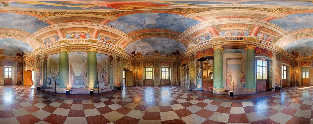
Environmental Camera
A camera model that traces rays in all directions around a point in the scene, giving a 2D view of everything that is visible from that point. Such type of images is particularly useful because it represents all of the incident light at a point on the scene.
Other Models
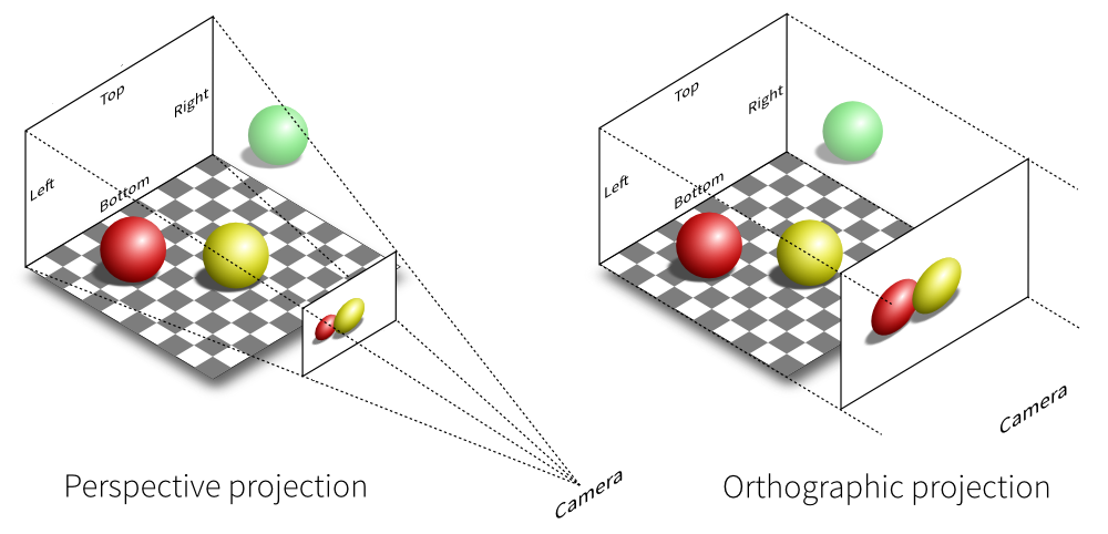

Orthographic Camera
The orthographic transformation takes a rectangular region of the scene and projects it onto the front face of the box that defines the region. It doesn’t give the effect of foreshortening—objects becoming smaller on the image plane as they get farther away—but it does leave parallel lines parallel, and it preserves relative distance between objects.
Environmental Camera
A camera model that traces rays in all directions around a point in the scene, giving a 2D view of everything that is visible from that point. Such type of images is particularly useful because it represents all of the incident light at a point on the scene.
Other Models

Thin Lens Model
Infinitely small pinhole
Theoretical (non-physical) model | Sharp image everywhere | Infinite depth of field | Too dark image in reality
Diffraction effects in reality
optical axis
screen plane

Thin Lens Model
Use Focusing Lens to Enlarge The Aperture
Under the thin lens approximation, incident rays that are parallel to the optical axis pass through the focal point of the lens (the one located behind the lens). If the screen plane is placed at a distance equal to the focal length behind the lens, then objects infinitely far away will be in focus, as they image to a single point on the film.
optical axis
screen plane
Thin Lens Model
Gaussian Lens Equation
For points in the scene at a depth g from a thin lens with focal length f, the Gaussian lens equation relates the distances from the object to the lens and from lens to the image of the point.
optical axis
screen plane
Thin Lens Model
Circle of Confusion
A point that doesn’t lie on the plane of focus is imaged to a disk on the screen plane, rather than to a single point. The boundary of this disk is called the circle of confusion. The size of the circle of confusion is affected by the diameter of the aperture that light rays pass through, the focal distance, and the distance between the object and the lens. This effect is known as Depth of Field.
optical axis
screen plane
Depth of Field
The thin lens model makes it possible to render images with blur due to depth of field

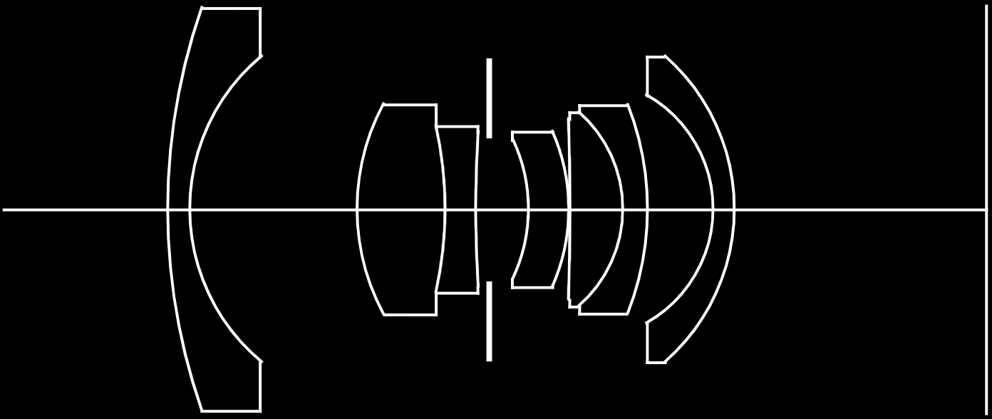
Thick Lens Model
The Realistic Camera Model simulates the focusing of light through lens systems to render more realistic images.

Implementation
... is based on ray tracing, where the camera follows ray paths through the lens elements, accounting for refraction at the interfaces between media (air, different types of glass) with different indices of refraction, until the ray path either exits the optical system or until it is absorbed by the aperture stop or lens housing. Rays leaving the front lens element represent samples of the camera’s response profile.
Camera obscura
aka pinhole camera
Camera obscura
aka pinhole camera
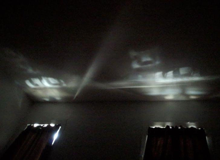
This optical effect can also be observed in a narrow slit
Camera obscura
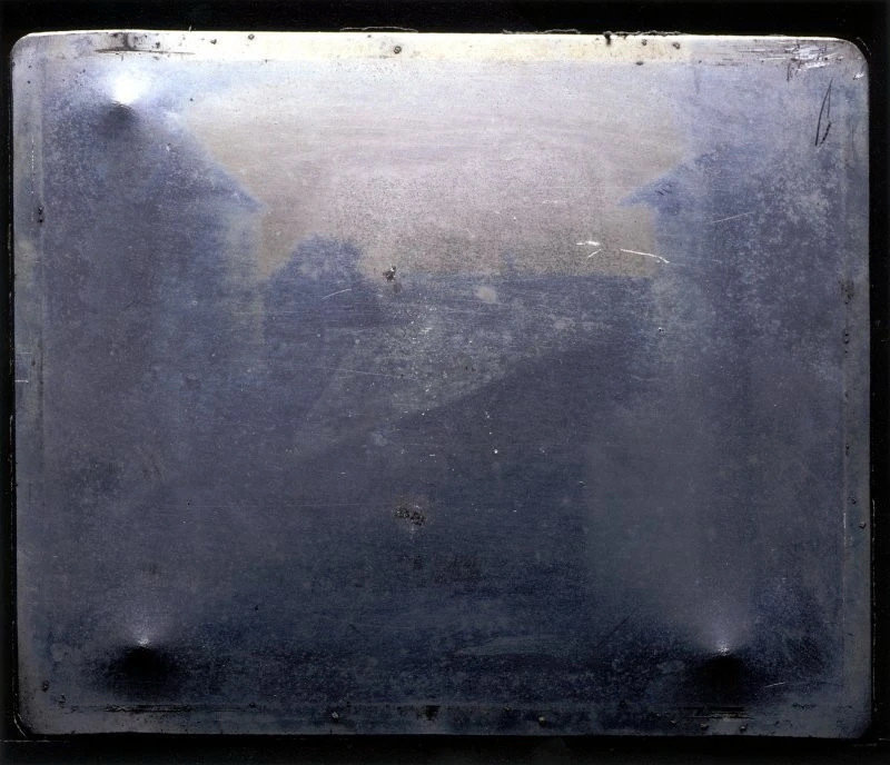
The First Photo ever taken
8 hours exposure "View from the Window at Le Gras" taken by Nicéphore Niépce in a commune in France called Saint-Loup-de-Varennes somewhere between 1826 and 1827.
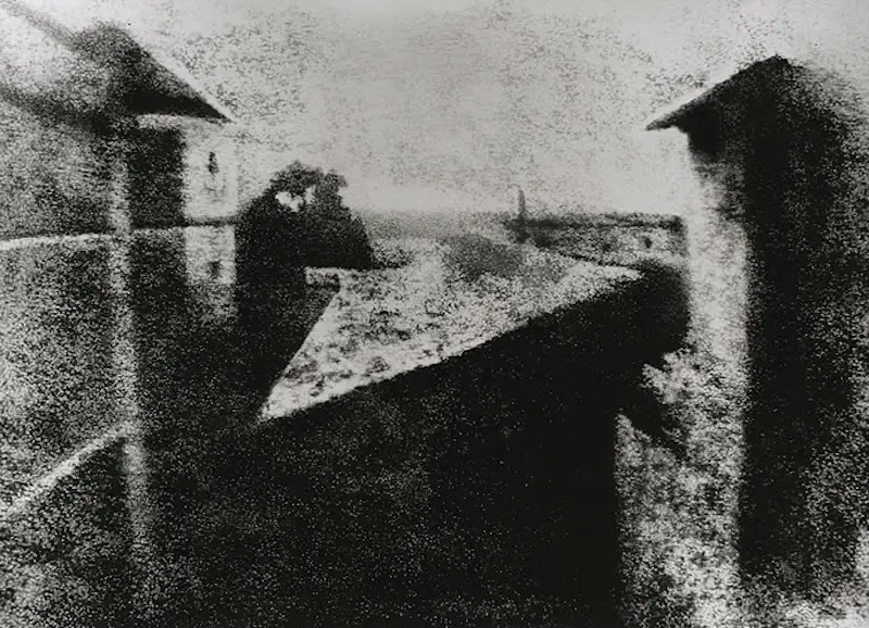
Early Photography
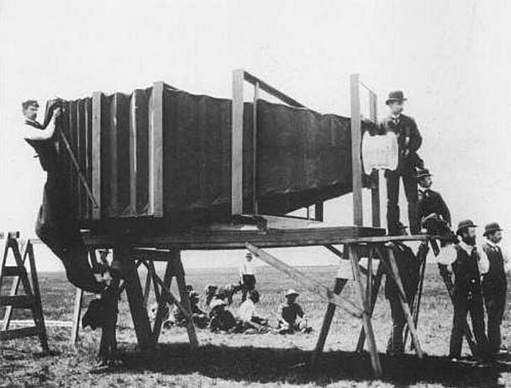
One of the first cameras with lens
It was the world’s largest camera back in 1900, built for the specific purpose of shooting the largest photo in the world of the “handsomest train in the world.”
Early Photography
The unsettling art of death photography
Long exposures when taking photographs meant that the dead were often seen more sharply than the slightly-blurred living, because of their lack of movement
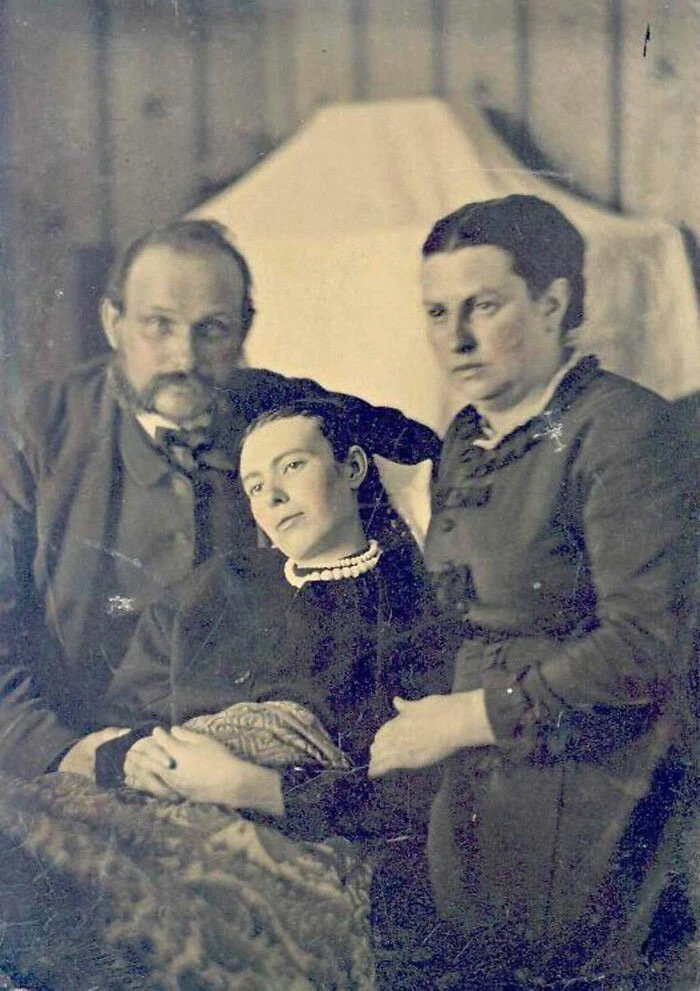
Victorian era post-mortem family portrait of parents with their deceased daughter (approximately 1905)
Early Photography
One the first selfies
In 1914, Grand Duchess Anastasia Nikolaevna of Russia took a picture of herself in front of a mirror to send to a friend, becoming one of the first teenagers to take a selfie!
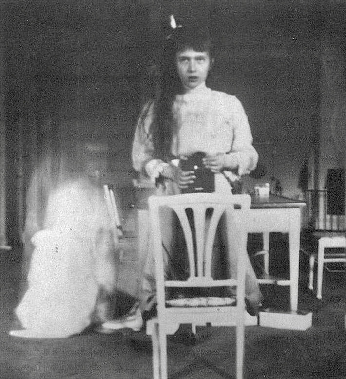
I took this picture of myself looking at the mirror. It was very hard as my hands were trembling.