Play
Physical Computing
with Syaz
B-DC 123
Computation in Design 2
2024
syazwan.hanif@lasalle.edu.sg
Physical Computing
Play
Physical Computing
with Syaz
B-DC 123
Computation in Design 2
2024
Physical Computing
To prepare
To do
Please upload all workshop outcomes to the shared Google Drive

Arduino
Computation in Design 2
2024
Physical Computing
9
10
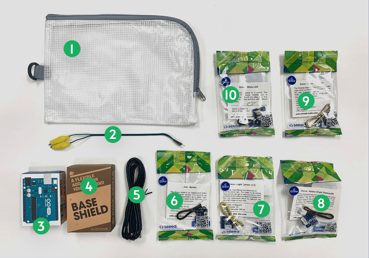
Bag
Wires
Arduino Board
Grove Shield
USB Cable
Button
Light sensor
Rotary Angle Sensor (Potentiometer)
Vibration Motor
LED Light
D5
D3
A0
A1
Session 1
B-DC 123
D4
1
2
3
4
5
6
7
8
What is physical computing?
23 - 24
Computation in Design 2
2024
Physical Computing


Session 1
B-DC 123
Outline
23 - 24
Physical Computing
Introduction to Sensors & Actuators
Computation in Design 2
2024
Physical Computing
What is physical computing?
How do we use sensors & actuators to accept input & release output to and from the physical world, how does interface with the digital
How to use the Arduino & Grove Shield & various sensors & actuators
Build an interactive artwork showcasing interaction of physical and digital.
Capture your whole process with photos and videos
Share with the class your interactive thing
Demo
Activity - Bring Me To Life
Documentation
Session 1
Session 2
Presentation
B-DC 123
Physical Computing
Physical computing refers to the design and implementation of interactive systems that bridge the digital and physical worlds. It involves using hardware and software to create systems that can sense and respond to the physical environment.
Key components of physical computing include:
-
Sensors: Devices that can detect physical inputs from the environment, such as light, temperature, motion, or sound.
-
Actuators: Components that can take digital information and convert it into physical actions, such as motors, LEDs, or speakers.
-
Microcontrollers: Small, programmable computers that serve as the brain of a physical computing system. They read input from sensors, process data, and control actuators.
-
Programming: Writing code to define the behavior of the system, including how it responds to input from sensors and how it controls actuators.


Computation in Design 2
2024
Physical Computing
Session 1
B-DC 123
B-DC 123
Computation in Design 2
2024
Physical Computing
Actuators
Sensors



MicrocontrollersWorld
ProgrammingSession 1
Arduino
B-DC 123
Computation in Design 2
2024
Physical Computing
Actuators
Sensors


MicrocontrollersWorld

ProgrammingSession 1

p5.jsArduino x p5.js
B-DC 123
Computation in Design 2
2024
Physical Computing
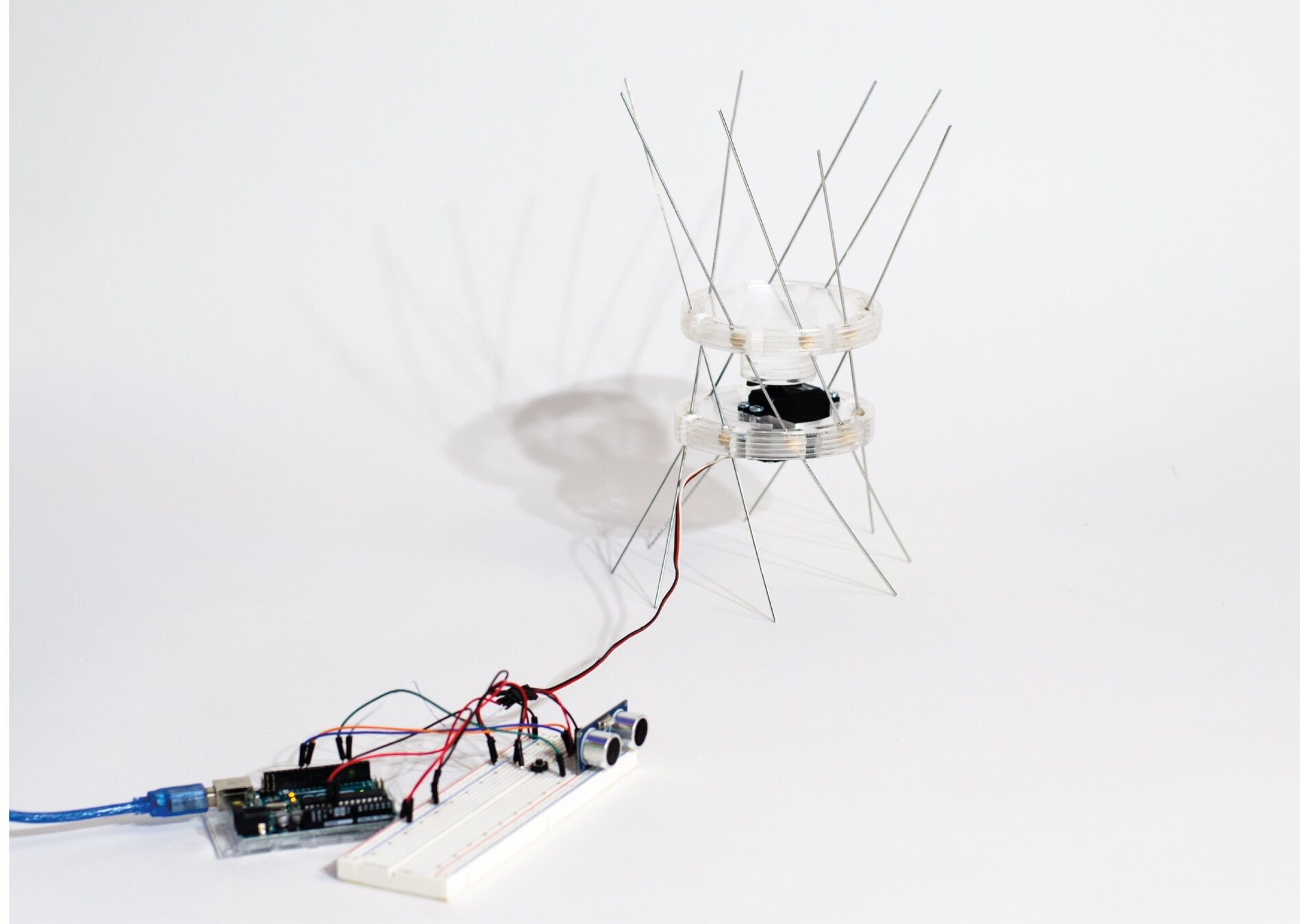
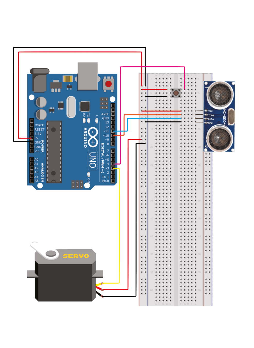
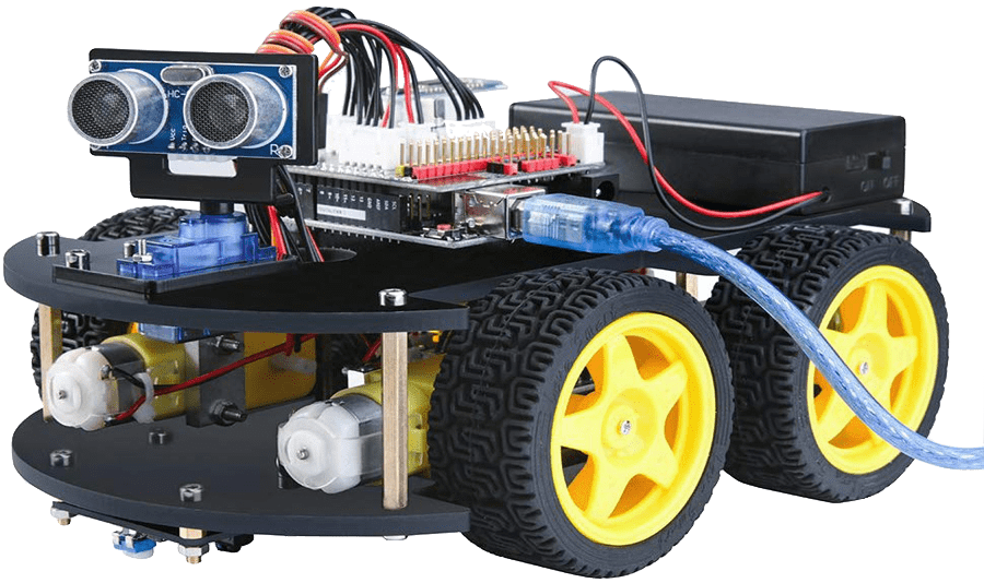
Arduino with Ultrasonic Sensor & Servo, connected through a breadboard

Actuators
Sensors
Microcontrollers
World
Programming

Session 1
Why?
This physical computing exercise aims to experiment with simple input and output mechanisms that utilise electronics.
We extend traditional design products into the digital sphere and explore how design can be applied to physical applications that a user can interact with to create physical and tangible experiences.
Through prepared materials and electronic components, students will design a simple physical interaction that demonstrates how a physical input triggers a digital output and vice versa.
Computation in Design 2
2024
Physical Computing
Session 1
B-DC 123
What's possible?


TAMI - an intuitive approach to the learning of trigonometry
Walk Walk Dance - an interactive pathway of lines that trigger different musical patterns, transforming the act of walking into a collaborative performance

LiquidMidi - An experimental modular textile interface for sonic interactions, exploring aesthetics and morphology on contemporary interaction design.
Mechanical Mirrors - use sensors and motors to rearrange objects into a mirror-image of whoever stands in front of them
Computation in Design 2
2024
Physical Computing
Session 1
B-DC 123

Lines - Lines attached to the wall, on the floor and hanging from the ceiling in combination with sensors and electronics are forming three novel music instruments
Computation in Design 2
2024
Physical Computing
Session 1
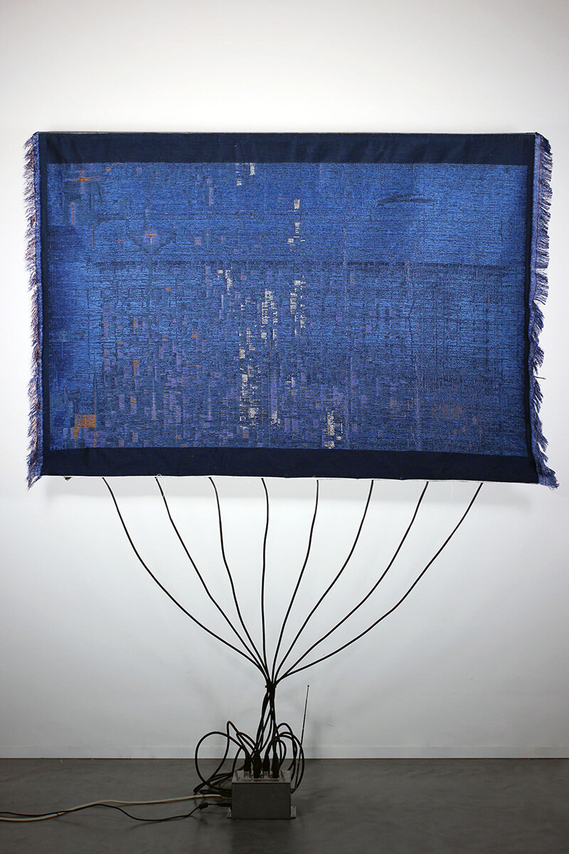
Wifi Tapestry - dynamic wall hanging that visualises the wireless activity of a space. The tapestry visualises the ever changing "landscape" of radio frequencies around us.
B-DC 123

Material Expressions No2 - Electromyography (EMG) electrodes attached to the chest of the knitter trigger sounds in a MIDI synthesizer with each beat of the performer's heart. The heartbeat simultaneously actuates a motor to unravel the scarf being continuously knit during the performance.

Can't Help Myself - Placed behind clear acrylic walls, their robot has one specific duty, to contain a viscous, deep-red liquid within a predetermined area. When the sensors detect that the fluid has strayed too far, the arm frenetically shovels it back into place, leaving smudges on the ground and splashes on the surrounding walls.
Reflect on the references,
- Which did you like, which did you prefer less?
- How have these examples broadened your perspective on what physical computing is?
- What ideas sprouted out from what you have seen?
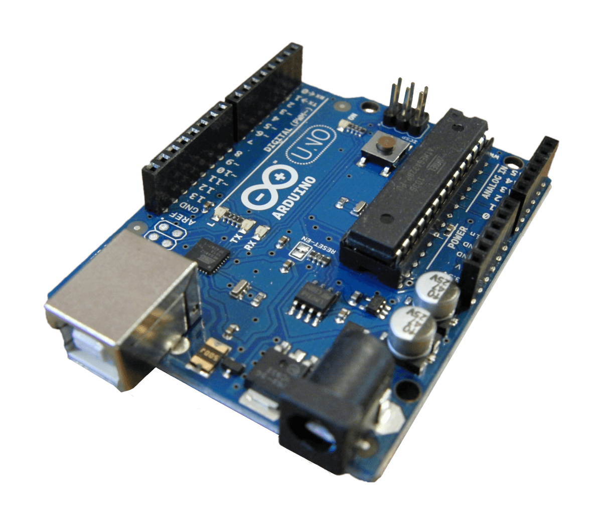
What is... an Arduino?
Arduino is an open-source electronics platform that consists of both hardware and software components. It provides a simple and accessible way for individuals, including hobbyists, artists, and students, to create interactive electronic projects. The Arduino platform includes an easy-to-use integrated development environment (IDE) for programming, as well as a variety of microcontroller boards.
Computation in Design 2
2024
Physical Computing
Session 1
B-DC 123
Demo
Arduino Demonstration
B-DC 123
Computation in Design 2
2024
Physical Computing
15
Arduino
Computation in Design 2
2024
Physical Computing
In this exercise you together with your group will be given a small electronics prototyping kit which includes an Arduino board and a Grove Shield (What is an Arduino, what is a Grove Shield? More in the next slide(s)).
With this kit you are able to try out simple input and outputs like LED lights, buttons or knobs. Why should you know about this as a designer?
Session 1
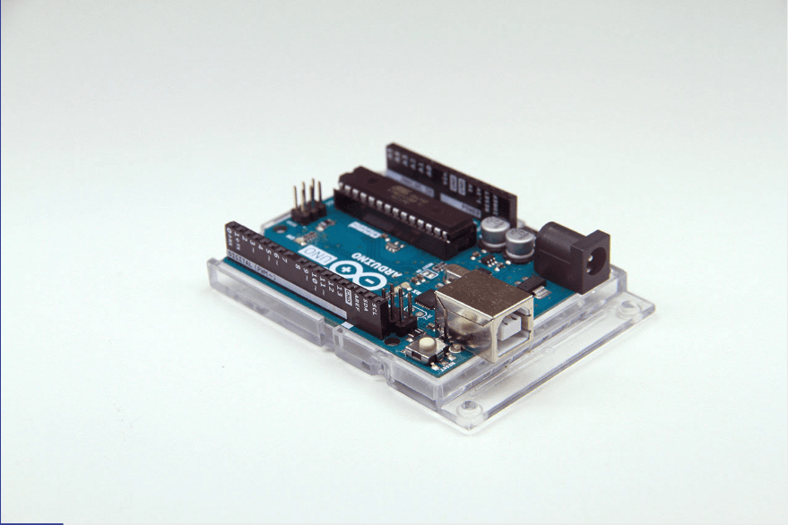
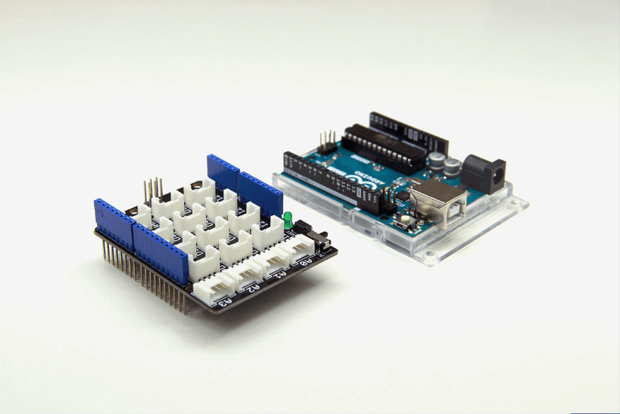
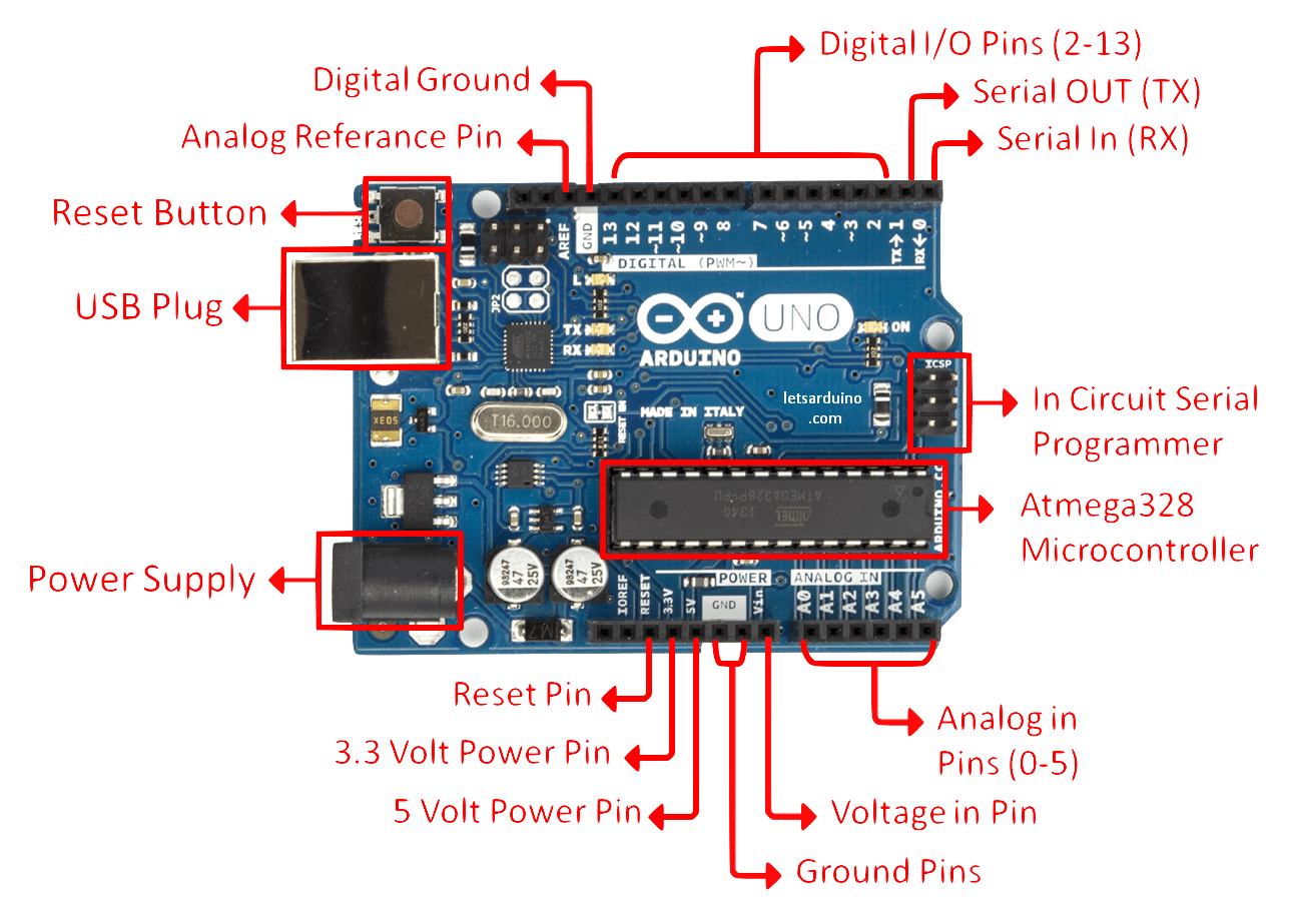
Arduino Uno
Arduino Uno + Grove Shield
B-DC 123
Arduino
Computation in Design 2
2024
Physical Computing
Arduino Uno board with Grove Shield
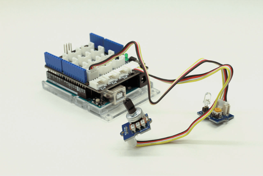
Arduino Uno board with Grove Shield and two electrical components (potentiometer as input, LED as output)
As a designer you may work on projects that go beyond the traditional scope of print, app or web design and you may be tasked to venture out into building interactive interfaces.
Interaction design, Exhibition design, Experience design, Interactive products, Experimental design or Research.
B-DC 123
Session 1
Computation in Design 2
2024
Physical Computing
Session 1
B-DC 123
Arduino IDE
Computation in Design 2
2024
Physical Computing
Session 1

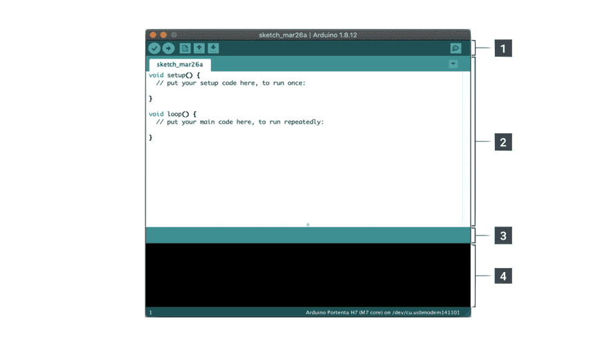
1. A Toolbar with buttons for common functions and a series of menus. The toolbar buttons allow you to verify and upload programs, create, open, and save sketches, and open the serial monitor.
2. The message area, gives feedback while saving and exporting and also displays errors.
3. The text editor for writing your code.
4. The text console displays text output by the Arduino Software (IDE), including complete error messages and other information.
B-DC 123
Computation in Design 2
2024
Physical Computing
Session 1
Code is all the same...
function setup() {
  createCanvas(400, 400);
  // where you set up the p5 document
}

function draw() {
  background(220);
  // where you carry out actions repeatedly
}
void setup() {
// put your setup code here, to run once:
}
void loop() {
// put your main code here, to run repeatedly:
}
p5.js Starter Code
Arduino Starter Code
B-DC 123
Computation in Design 2
2024
Physical Computing
Session 1
Basic Arduino Functions
-
-
-
-
Configures the specified pin to behave either as an input or output.
Reads the value from a specified digital pin, either HIGH or LOW.
Write a HIGH or a LOW value to a digital pin.
Reads the value from the specified analog pin. Arduino boards contain a multichannel, 10-bit analog to digital converter. This means that it will map input voltages between 0 and the operating voltage(5V or 3.3V) into integer values between 0 and 1023.
Writes an analog value (PWM wave) to a pin.
Pauses the program for the amount of time (in milliseconds) specified as parameter.
-
-
B-DC 123
Arduino
Computation in Design 2
2024
Physical Computing

9
10
Bag
Wires
Arduino Board
Grove Shield
USB Cable
Button
Light sensor
Rotary Angle Sensor (Potentiometer)
Vibration Motor
LED Light
D5
D3
A0
A1
Session 1
B-DC 123
D4
1
2
3
4
5
6
7
8
Follow Along!
How to download and setup Arduino software
How to connect Arduino and Grove Shield
Open your first Arduino sketch
Upload Arduino sketch to Arduino board
Make changes to example Arduino sketches
Make changes to example p5.js code
B-DC 123
Computation in Design 2
2024
Physical Computing
60
p5
A
A
A
A
p5
IN
OUT
Computation in Design 2
2024
Physical Computing
Data flow


A
p5
Session 1
B-DC 123
Button
/*
Arduino Intro Example 1 (Activity 1.1)
This is an Arduino sketch to turn on an LED when a Button is pressed, all connected to the Arduino
*/

#define LED_PIN 3
#define BTN_PIN 4

void setup() {
  // put your setup code here, to run once:
  Serial.begin(9600);
  pinMode(LED_PIN, OUTPUT);
  pinMode(BTN_PIN, INPUT);
}

void loop() {
  // put your main code here, to run repeatedly:
  if (digitalRead(BTN_PIN) == HIGH) {
        digitalWrite(LED_PIN, HIGH);
        /* Uncomment the code below, to make the LED blink every 0.2s
        delay(200);
        digitalWrite(LED_PIN,LOW);
        delay(200);
        */
  }
  else {
    digitalWrite(LED_PIN, LOW);
  }
}

/*
Instructions:
1) connect LED to D3.
2) connect BUTTON to D4.
3) connect arduino to laptop via USB cable

4) upload sketch using the  -> button on the top left of the arduino IDE window.
5) wait for uploading to be done.
6) Press button
*/
B-DC 123
Computation in Design 2
2024
Physical Computing
Input
Output
LED
A
A
Activity 1.1
Session 1
Digital In, Digital Out
Physical
Physical
Light Sensor
/*
Arduino Intro Example 2 (Activity 1.2)
This is an Arduino sketch to affect the Vibration motor using the Light Sensor (LDR), all connected to the Arduino
*/

#define BUZZER_PIN 5
#define LIGHT_SENSOR A0

void setup() {
  // put your setup code here, to run once:
  Serial.begin(9600);
  pinMode(BUZZER_PIN, OUTPUT);
  pinMode(LIGHT_SENSOR, INPUT);
}

void loop() {
  // put your main code here, to run repeatedly:

  //values from light sensor is mapped into a different range (0-255) and used for buzzer
  int data = analogRead(LIGHT_SENSOR);
  //Serial.println(data);
  int mappedVal = map(data, 0, 1000, 0, 255);
  Serial.println(mappedVal);


  analogWrite(BUZZER_PIN, mappedVal);
  delay(50);
  analogWrite(BUZZER_PIN,0);
  delay(50);
}

/*
Instructions
1) connect buzzer to D5.
2) connect light sensor to A0.
3) connect arduino to laptop via USB cable
4) upload sketch using the  -> button on the top left of the arduino IDE window.
5) wait for uploading to be done.
6) Play with light
*/
B-DC 123
Computation in Design 2
2024
Physical Computing
Input
Output
Vibration Motor
A
A
Activity 1.2
Session 1
Analog In, Digital Out
Physical
Physical
B-DC 123
Computation in Design 2
2024
Physical Computing
/*
Physical-To-Digital (P2D) (Activity 1.3)
This is an arduino sketch to connect arduino to p5.js via serial.
The corresponding p5.js sketch can be found at "https://editor.p5js.org/nawzaysfinah/sketches/ZPk_TdocX"
*/

#define POTENTIOMETER_PIN A1

void setup() {
  // put your setup code here, to run once:
  Serial.begin(9600);
}

void loop() {
  // put your main code here, to run repeatedly:
  int data = analogRead(POTENTIOMETER_PIN);
  int mappedVal = map(data, 0, 1023, 0, 255);
  Serial.println(mappedVal);
  delay(100);
}

/*
1) connect potentiometer to A1.
2) connect arduino to laptop via USB cable
3) upload sketch using the  -> button on the top left of the arduino IDE window.
4) close serial monitor, if its open.
5) wait for uploading to be done and proceed to p5.js and open PhysicalComputing_P2D
*/
Potentiometer
Input
Output
A
p5
Activity 1.3
Session 1
Laptop Display
Analog In, Digital Out
Physical
Digital
B-DC 123
Computation in Design 2
2024
Physical Computing
/*
DIGITAL-to-PHYSICAL (Activity 1.4)
This is an arduino sketch to use data from serial to move the arduino.
To be used with p5.js sketch (https://editor.p5js.org/nawzaysfinah/sketches/s97bq5bZe )

*/

#define BUZZER_PIN 5
#define LED_PIN 3

void setup() {
  Serial.begin(9600);
  pinMode(BUZZER_PIN , OUTPUT);
  pinMode(LED_PIN , OUTPUT);
}

void loop() {
  if (Serial.available() > 0) {
    String input = Serial.readStringUntil('\n');
    //if there is data coming through
    if (input.length() > 0) {

      //check what is coming through
      if(input == "1"){
        digitalWrite(BUZZER_PIN, HIGH);
        digitalWrite(LED_PIN, HIGH);
      }
      else{
        digitalWrite(BUZZER_PIN, LOW);
        digitalWrite(LED_PIN, LOW);
      }
    }
  }
}


/*
Instructions
1) connect Buzzer to D5.
2) connect arduino to laptop via USB cable
3) Stop any previous p5.js running
3) upload sketch using the  -> button on the top left of the arduino IDE window.
4) close serial monitor, if its open.
5) wait for uploading to be done and proceed to p5.js to open PhysicalComputing_D2P
6) Interact with the sketch and observe the arduino
*/
Mouse
Input
Output
p5
A
Activity 1.4
Session 1
Buzzer
Digital In, Digital Out
Digital
Physical
Document ✍🏽
Document all work from Session 1
Save p5.js sketches & Arduino code
Collect screenshots of outcomes
Take photos/videos of your experiments
Write your reflection about learning physical computing
B-DC 123
Computation in Design 2
2024
Physical Computing
10
Session 1
Conceptualise ✍🏽
Sketch concept for final activity on paper
Groups to be reasonable and confident to implement Arduino
Groups to be aware of time and time management
Sketch input and output flow of data through sensors, actuators, Arduino & p5.js
B-DC 123
Computation in Design 2
2024
Physical Computing
15
Session 1
Review ✍🏽
Review concepts & prepare to build input, design the output
How to create an interactive object?
What inputs required?
How will the output be designed?
B-DC 123
Computation in Design 2
2024
Physical Computing
30
Session 2
Activity 2: Bring me to life
Work in your group
Build a simple input-output circuit based on the code samples provided
Ideate & formulate a simple, intuitive and effective idea
Build an object around the input component
Build an object around the output component
Test & demonstrate your creation, how did others respond to your interactive object.
Document process, object, feedback and outcome.
B-DC 123
Computation in Design 2
2024
Physical Computing
Process
Note
Your project must be either
A
L
A
L
OR
Session 2
80
Homework 😱
B-DC 123
Computation in Design 2
2024
Physical Computing
Session 1 - 2
Complete the Play exercise
Document your outcomes as required
See section Deliverables
Pass complete Arduino Kit to Syaz next Wednesday Morning, 31st jan before 9:30am at D501
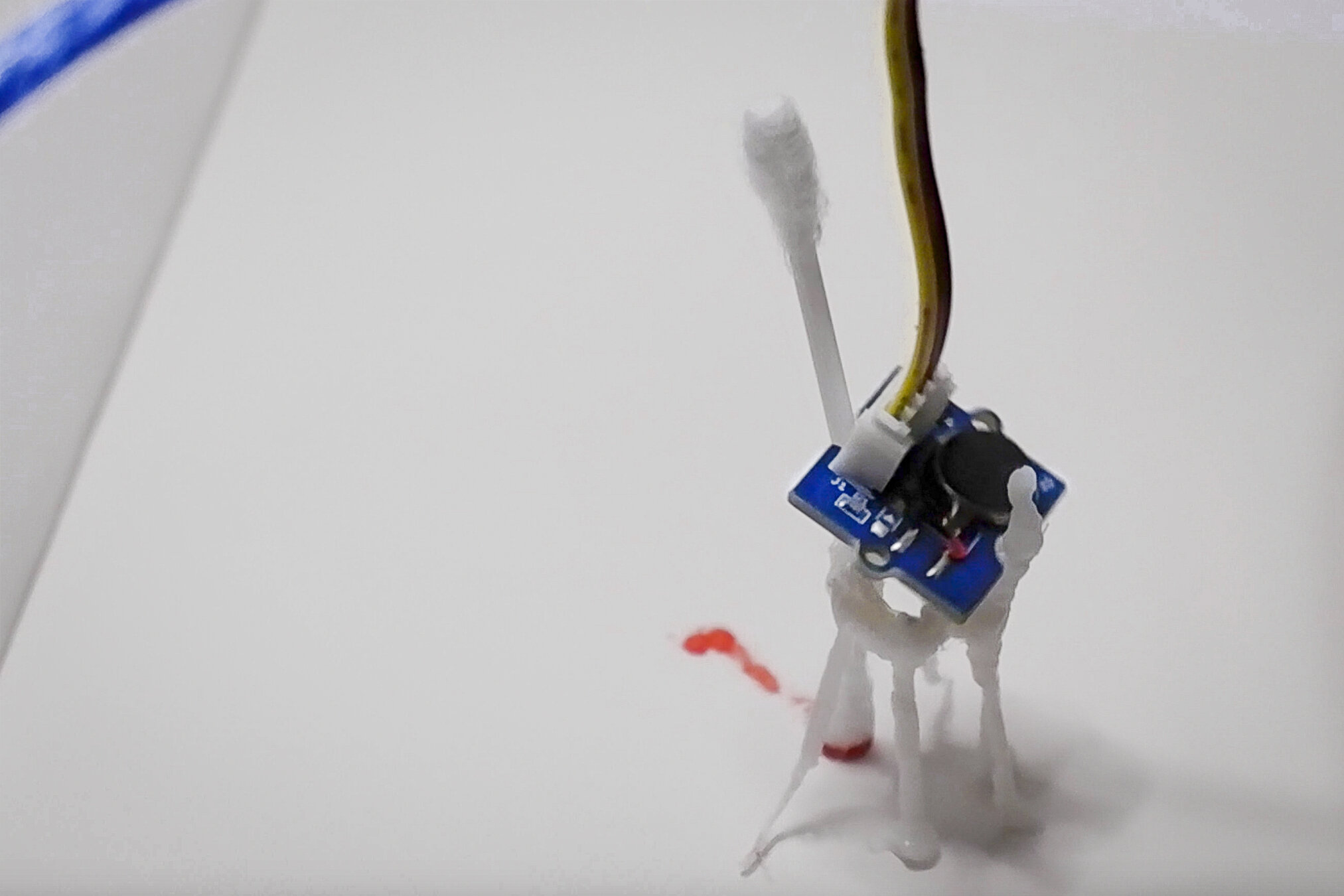
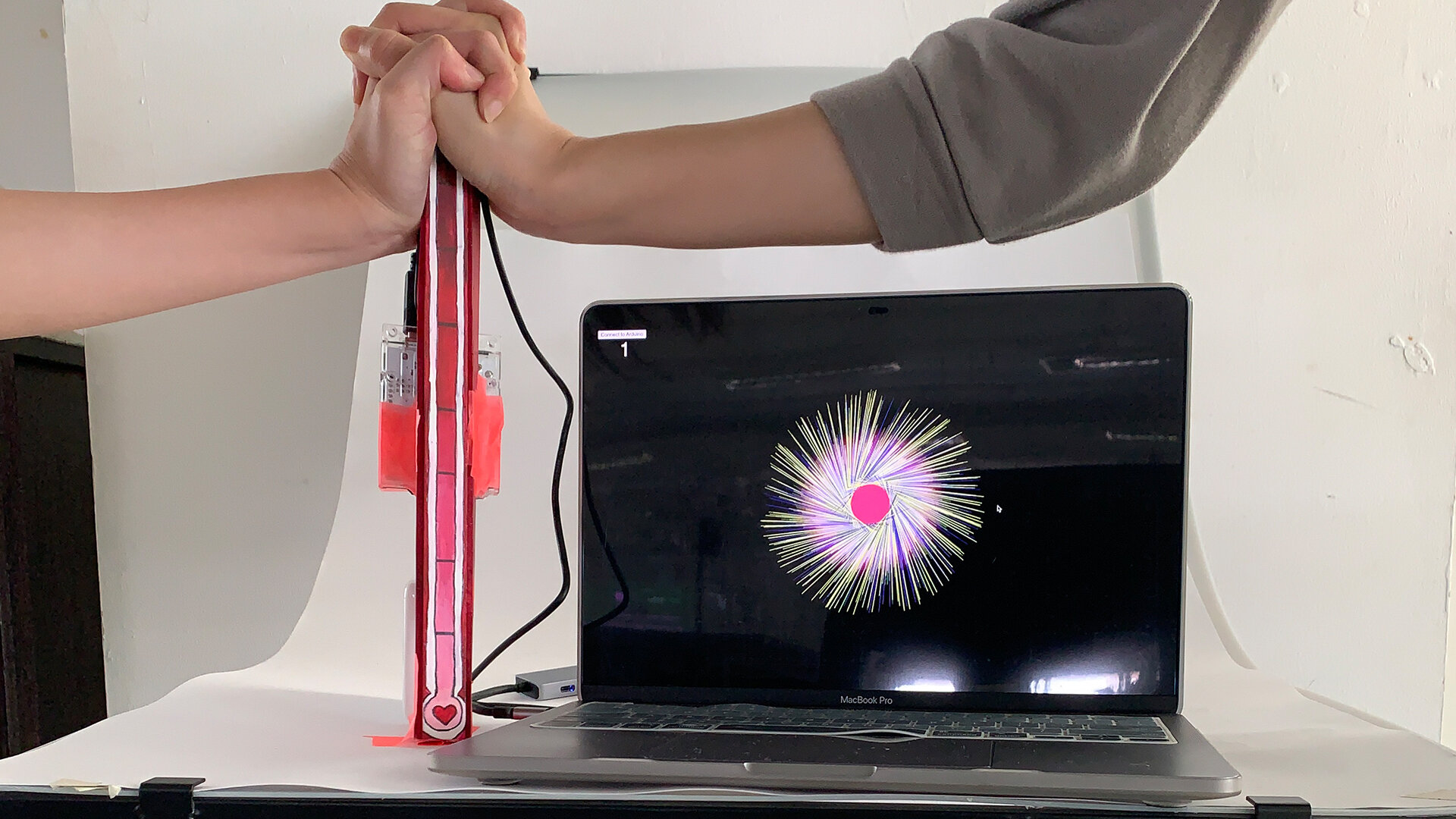
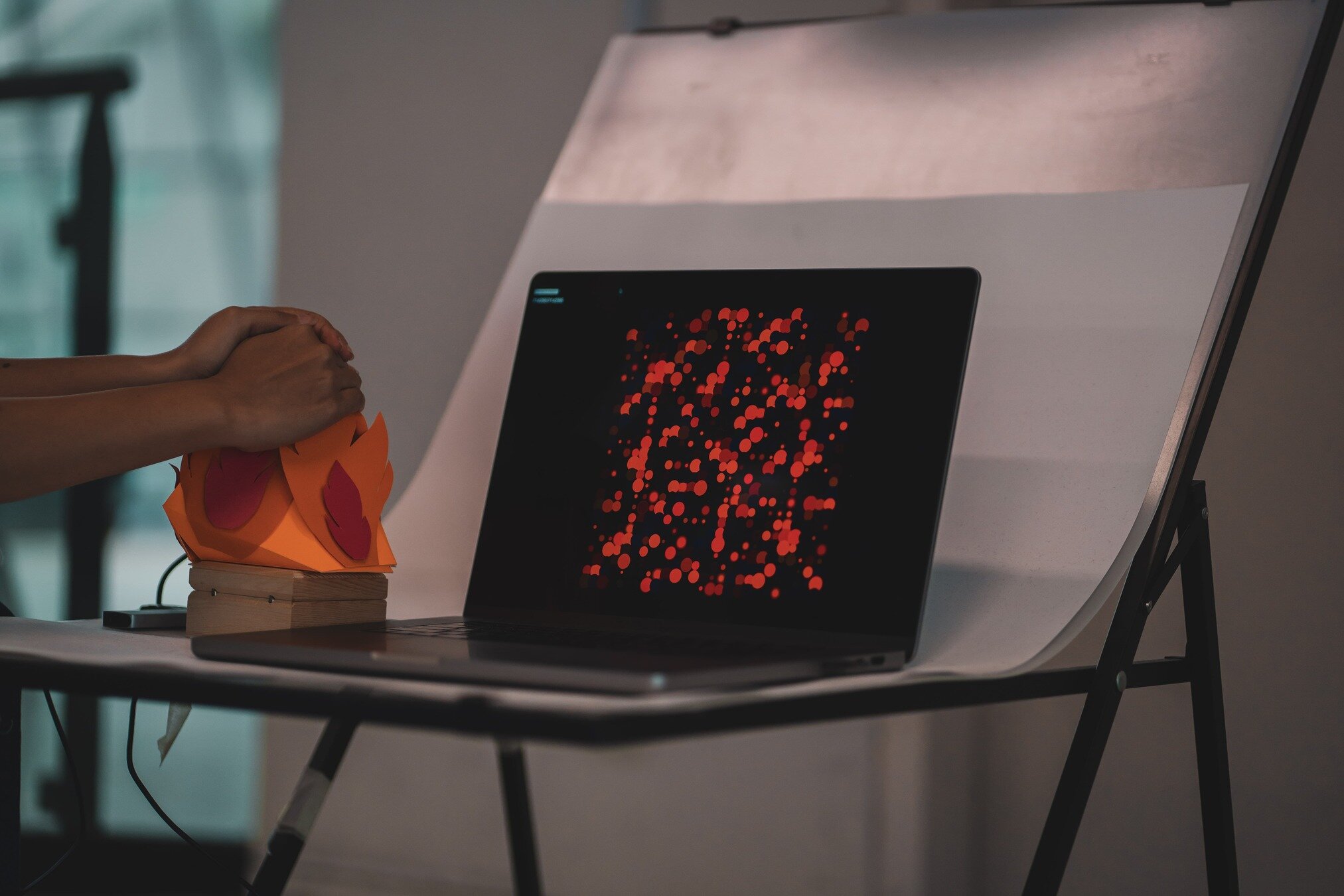
Past Student Works
Chon Hui Chin & Wong Mindy
Jun Yun So
B-DC 123
Computation in Design 2
2024
Physical Computing
Aaron & Aparupa
Arduino
Computation in Design 2
2024
Physical Computing
Session 1
B-DC 123
Complete your deliverables before your next workshop
.zip file of Arduino & p5.js code
images of process & outcomes
process video
outcome video
write up
1
5 - 7
1
1
1
x
x
x
x
x
Computation in Design 2
2024
Physical Computing
Deliverables
Objects stored in a safe place, required in week 12 for Open Studios
Documentation of object, process and outcome in your CPJs
Images minimum size 1920 x 1080 pixels, format .jpg
Video size 1080p, format .mp4
Important Retain a very good image quality for both, images & video
Objects stored in a safe place, required in week 12 for Open Studios
Documentation of object, process and outcome
B-DC 123
