mm-Wave on Wheels: Practical 60 GHz Vehicular Communication Without Beam Training
Yung-Sheng Lu
OCT 31, 2017
@NCTU-CS
Communication Systems and Networks (COMSNETS) '17
Adrian Loch, Arash Asadi, Gek Hong Sim, Joerg Widmer, Matthias Hollick
Outline
-
Abstract
-
Introduction
-
Related Work
-
System Model
-
Experiments
-
Evaluations
-
Conclusions
-
References
Abstract
Abstract
-
Scenario
-
The contact time during which a mobile node is in range of a fixed road side unit (RSU) is short.
-
When transmitting a large amount of information, short contact times become problematic.
-
Abstract (cont.)
-
Current research
- Millimeter-wave (mm-Wave) communication provides larger throughput than the existing technologies.
- The mm-Wave band has extremely high attenuation.
-
Problem
Can the high throughput of mm-Wave make up for the reduction in the contact time?
Abstract (cont.)
-
Solution
Analyze the trade-off and design a first-of-its-kind practical mm-Wave vehicular testbed to evaluate the resulting performance.
-
Experiments
- Consider alternative locations for the RSU other than at the side of the road.
- Use fixed beam-steering at both the car and the RSU, thus avoiding costly beam-training.
Introduction
Introduction
-
Millimeter-wave (mm-Wave)
-
Achieve multi-gigabit-per-second performance
-
Successfully combined with other vehicular systems
-
Extremely high attentuation
-
Uses directional antennas to overcome
-
-

Introduction (cont.)
-
Highly mobile scenarios
-
How can transceivers perform efficient beam-steering at vehicular speeds such that they always reach each other?
-
Where shall mm-Wave antennas be located on cars?
-
Place the antenna on a pole on top of the car but stongly disagree with aethetic considerations
-
-
How wide shall the bandwidth of the mm-Wave antennas on a car be?
-
How much data can transceivers enchange in a mobile scenario?
-
Introduction (cont.)
-
First-of-its-kind mm-Wave vehicular testbed
-
Operating in the 60 GHz band
-
Consider the road side units (RSUs) to transmit data to vehicles
-
The data includes content of large volumes.
-
-
Propose an approach that eliminates the use of beem-steering by leveraging the characteristics of vehicular communications.
Introduction (cont.)
Related Work
Related Work
-
[1][2] Performs channel measurements in the 60 GHz band for links within a car and from the car to a unit located outside
- Not consider the effects of actual data transmission involving
- Not consider the effects of actual data transmission involving
-
[3] Focuses on the design of a frame structure for cellular mm-Wave networks operating at 28 GHz
- Not consider actual traffic
- Not consider actual traffic
- [4] Performs an in-depth indoor measurement characterizing the coverage, bit-rate, beam steering impact, blockage, and spatial reuse of 60 GHz links using a softare-radio platform
System Model
Definitions
-
Contact time
-
The time during which the RSU and the in-car-unit (ICU) can exchange data.
-
Directly related to the speed of the car and the distance that the car travels within the beam of the transmitter
-
Contact distance
-
-
Definitions (cont.)
-
Infrastructure
-
Transmitter: RSU
-
Receiver: ICU
-
-
Symbols
-
Transmission direction:
-
Transmit beamwidth at the RSU:
-

Definitions (cont.)
-
Three RSU Cases
-
At the road side
-
On top of a bridge
-
Within a roundabout
-

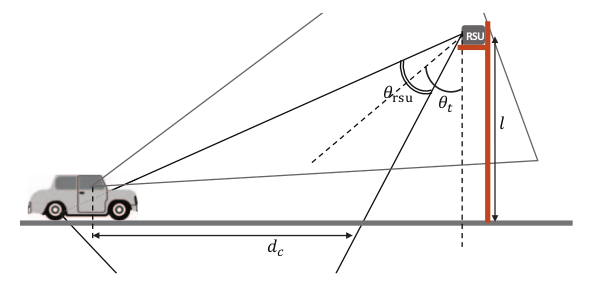

Fig.: At the road side.
Fig.: On top of a bridge.
Fig.: Within a roundabout.
RSU at the Road Side
-
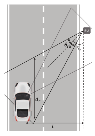
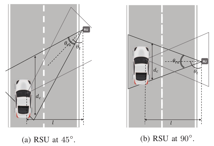
The contact distance between the RSU and the ICU
-
For
-
For
-

Fig.: RSU at .
contact distance
-
Transmission direction:
-
Transmit beam-width at the RSU:
RSU at the Road Side (cont.)
-
The contact time at which the vehicle is driving
-
We do not condiser angles .
-
Let
-
Let
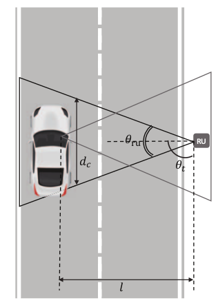
Fig.: RSU at .
-
Transmission direction:
-
Transmit beam-width at the RSU:
RSU at the Road Side (cont.)
-
While a wider beamwidth may provide a longer contact time, may also result in lower transmit rates since the antenna gain typically.
-
Optimal and
-
Contact time:
-
Transmission rate:
-

-
Transmission direction:
-
Transmit beam-width at the RSU:
RSU at the Road Side (cont.)
- Placing the RSU at the road side can result in reflections.
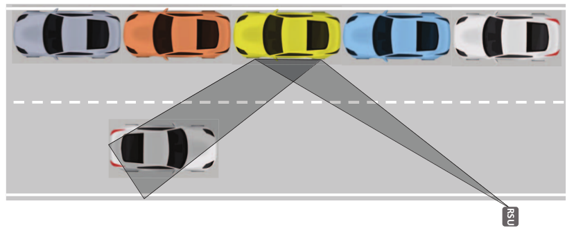
Fig.: Car reflection case. The row of cars are parked cars.
RSU on Top of a Bridge
-
The cars on the road cannot cause blockage.
-
The signal can receive all of the car from above.
-
May not hold when a car driving closely behind a large truck.
-


Large truck
Fig.: RSU located at the top of a bridge.
RSU within a Roundabout
-
The cars must slow down when driving in a roundabout.
-
Increases the contact time
-
-
Provides coverage in all directions
-
To compensate for the low gain of the omnidirectional antenna, the car can use a highly directional receive antenna.
-
The contact time for given a
roundabout of radius

-
Contact time:
-
Transmit beam-width at the RSU:
Experiments
Vehicular 60 GHz Testbed
-
Environment
-
RSU
-
Based on GNU Radio developed at RWTH Aachen
-
Along with a USRP X310 to generate a stream of 4-QAM modulated data
-
Sends this data to the external upconverter for transmission in the 60 GHz band
-
-
ICU
-
Carrier-frequency offset (CFO) compensation
-
Decoding
-
-
Vehicular 60 GHz Testbed (cont.)
-
Metrics
-
Receive time
Period of time during which the receiver gets packets. -
Contact time
Period of time during which the receiver is able to receive correct packets without bit errors. -
Others - throughput, BER, PER, SNR
-
Vehicular 60 GHz Testbed (cont.)
-
RSU Setup
-
Desktop PC
-
USRP X310
-
SiversIMA FC1005V/00 60 GHz upconverter
-
Horn antenna or omni-directional antenna
-
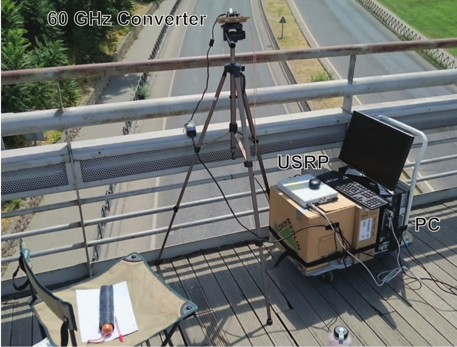

Vehicular 60 GHz Testbed (cont.)
-
ICU Setup - Same elements as the RSU
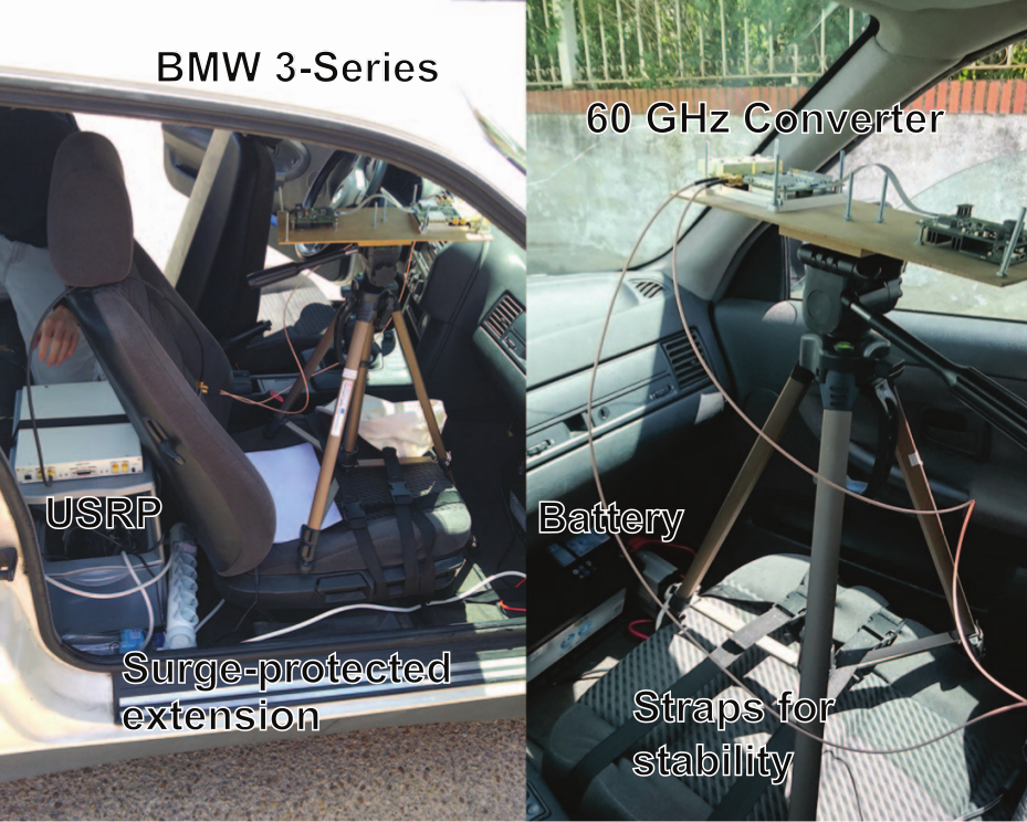
Vehicular 60 GHz Testbed (cont.)
-
Location
-
Temporarily installed the RSU at multiple locations in the city of Leganés, Spain.
-
All experiments were carried out under real traffic conditions at the beginning of August 2016.
-
Evaluations
RSU at the Road Side
-
Points the antenna of the RSU at and the ICU at
-
The faster the car,
-
the less time the transmit and the receive beams are aligned
-
the less packets are received
-
the lower the probability that we observe bit errors
-
Related to the antenna gain

RSU at the Road Side (cont.)
-
The wider the beam width, the larger the variance of SNRs.
Fig.: SNR distribution.
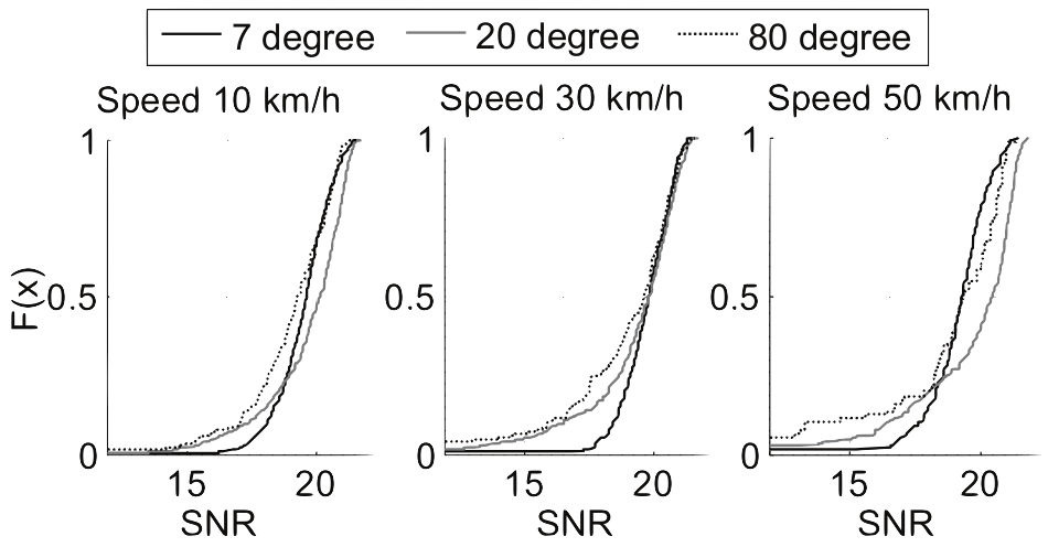
RSU at the Road Side (cont.)
-
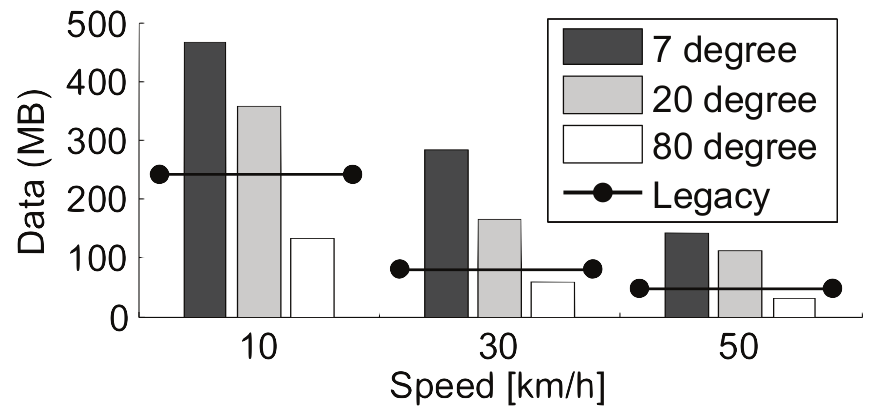
Compares with lagacy 802.11p-like WiFi
-
Assumes a circular range of 100 m and a fixed rate of 27 Mbps
-
Achieves higher throughput only holds for narrow beam width
Only holds for narrow beam
Fig.: 60 GHz vs. legacy WiFi.
RSU on Top of a Bridge
-
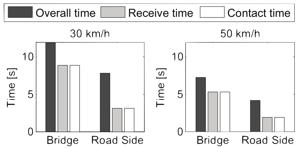
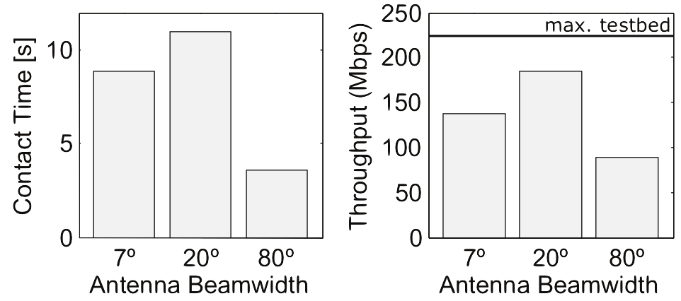
Achieves higher contact times in bridge scenario compared to the road side case
Fig.: Communication times.

RSU on Top of a Bridge (cont.)
-
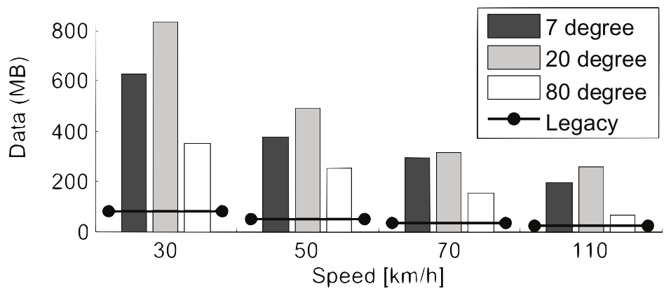
Achieves higher contact times in bridge scenario compared to the road side case
Fig.: In the Bridge Scenario.
Fig.: In Road Side Scenario.
The increase in contact
time when switching angles.


RSU on Top of a Bridge (cont.)
-
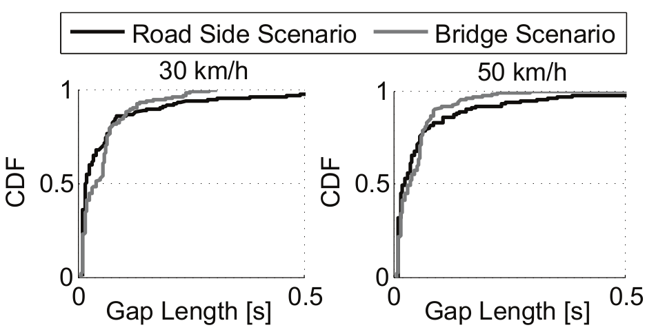
Communication gaps occur when antennas are temporarily misaligned due to, e.g., bump.
Fig.: Communication gaps.
RSU on Top of a Bridge (cont.)
-
The contact progress reflects the normalized contact time.
-
The bridge case is more stable than the road with bumps.
Fig.: SNR fluctuations.
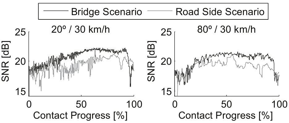
Shakiness has less influence.
RSU within a Roundabout
-
Considers an RSU placed at the center of a roundabout
-
The omnidirectional antenna has a peak of its radiation pattern when the car is driving through a roundabout.
30 km/h
Path loss
Path loss
Road Side Reflections

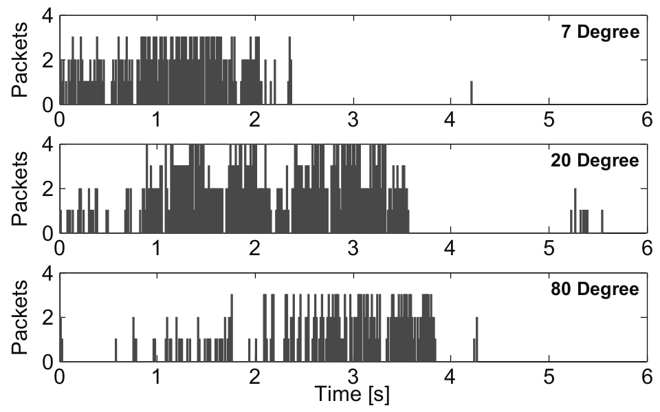
Fig.: Packet arriving at the ICU via a car reflection.
-
The length of the main burst increases with the beam width.
-
The reflected path becomes wider.
-
20 km/h
Isolated packets
Car Blockage
-
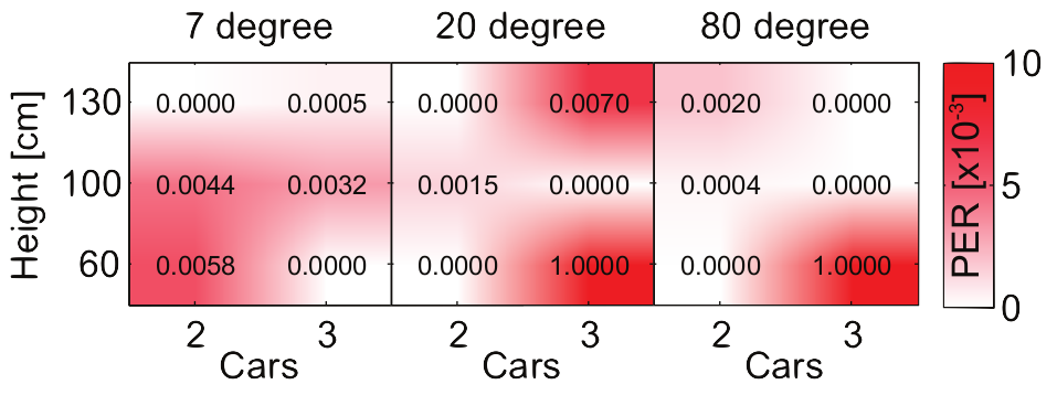
Higher heights results in lower PER.
-
Wider beam widths tend to yield better results.
-
The transmission through parallel cars is feasible.
-
Easily result in link loss
-

Fig.: PER for transimission through cars multiple heights.
Height


Conclusions
Conclusions
-
The road geometry and the arrival direction of cars are known in vehicular scenarios.
-
Fixed beam-steering and beam width angles
-
-
Builds a first-of-its-kind SDR-based practical vehicular testbed
-
Enables 60 GHz packet-level transmissions
-
-
Our approach is feasible and yields significant throughput gains compared to legacy 802.11p-based systems.
Contributions
-
A simple yet effective approach to select a fixed antenna steering for multiple RSU scenarios
-
at the road side, on a bridge, and in a roundabout
-
-
The impact of antenna beam width in the above RSU scenarios, and analytically optimize it
-
The impact of reflectors in vehicular scenarios
-
the walls of buildings or cars parked nearby
-
References
References
-
Related work
-
J. Blumenstein, T. Mikulasek, A. Prokes, T. Zemen, and C. Mecklen-brauker, "INtra-Vehicular Path Loss Comparison of UWB Channel for 3-11 GHz and 55-65 GHz," IEEE IXUWB, 2015.
-
E. Ben-Dor, T. S. Rappaport, Y. Qiao, and S. J. Lauffenburger, "Millimeter-Wave 60 GHz Outdoor and Vehicle AOA Propagation Measurements Using a Broadband Channel Sounder," IEEE GLOBECOM, 2011.
-
Y. Kim, H.-Y. Lee, P. Hwang, R. K. Patro, J. Lee, W. Roh, and K. Cheun, "Feasibility of Mobile Cellular Communications at Millimeter Wave Frequency," IEEE Journal of Selected Topics in Signal Processing, 2016.
-
S. Sur, V. Venkateswaran, X. Zhang, and P. Ramanathan, "60 GHz Indoor Networking Through Flexible Beams: A Link-Level Profiling," ACM SIGMETRICS Performance Evaluation Review, 2015.
-