ARDUINO WORKSHOP
MARGARITA BENITEZ + MARKUS VOGL
KSU ARCHITECTURE | FEBRUARY 5, 2015
MARGARITA BENITEZ
FASHION TECHNOLOGIST
ASSISTANT PROFESSOR
FASHION DESIGN
KENT STATE UNIVERSITY
MBENITEZ@KENT.EDU
MARKUS VOGL
ASSISTANT PROFESSOR
GRAPHIC DESIGN + INTERACTIVE MEDIA
MYERS SCHOOL OF ART
THE UNIVERSITY OF AKRON
MVV@UAKRON.EDU
Have Arduino software installed?
If not...
Download Link
FYI: In this presentation, any text in BLUE is a link.
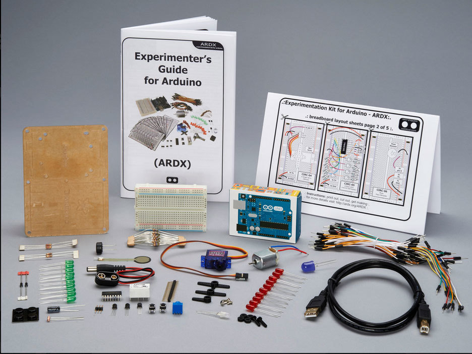
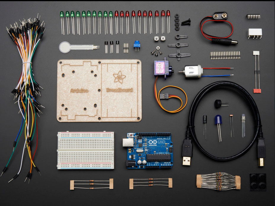
Kit Parts
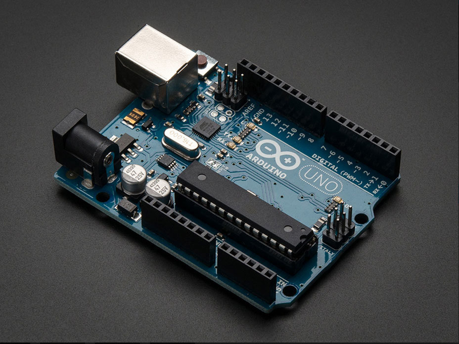
Arduino Uno | ATmega 328

USB Cable
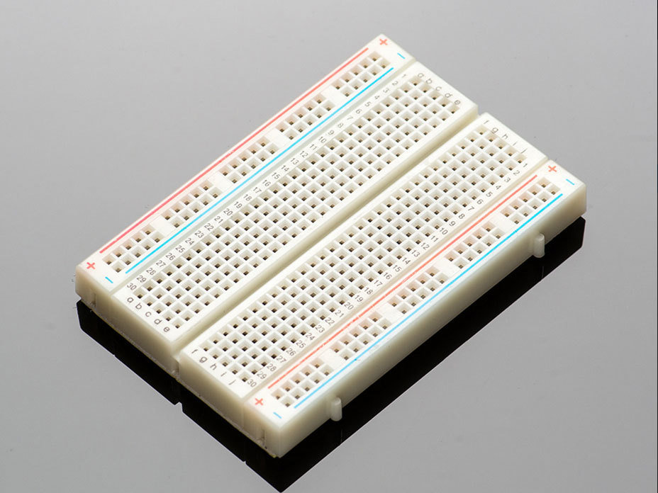
Breadboard (half-size)
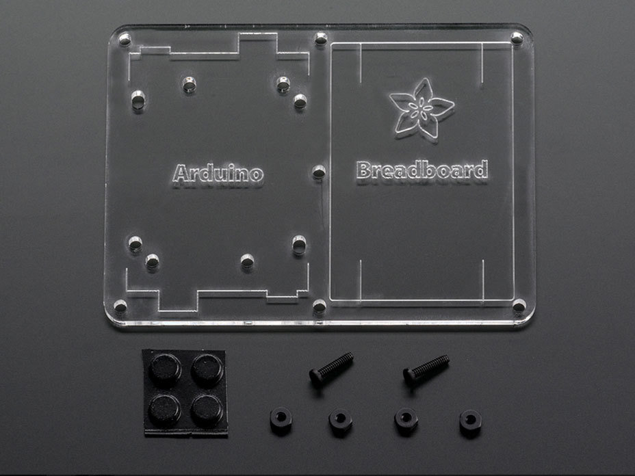
Mounting Plate (Assembly Instructions Link)
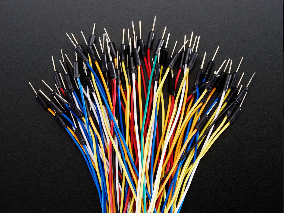
Jumper Wires

LEDs
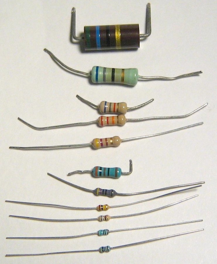
Resistors
These little guys come in different values. The color bands on them indicate different values. Pay extra careful attention to the color codes and values. The unit of measure used is the Ohm.
Kit contains:
560 Ohm x25
2.2k Ohm x3
10k Ohm x3
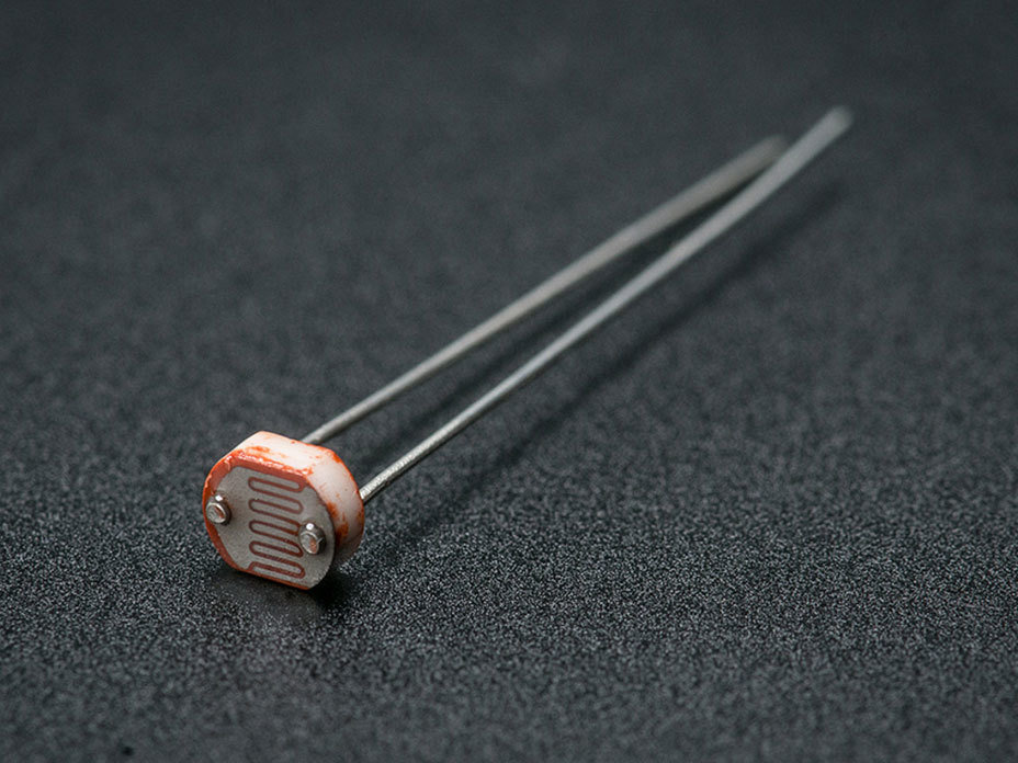
Photocell/Photoresistor
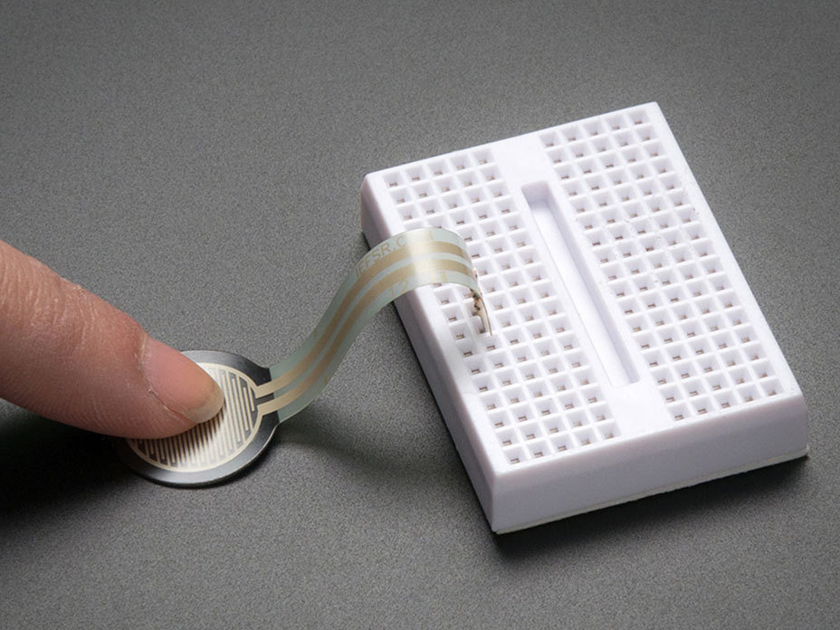
Force-Sensitive Resistor
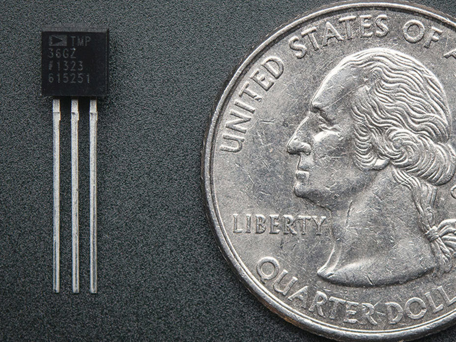
Temperature Sensor
Analog
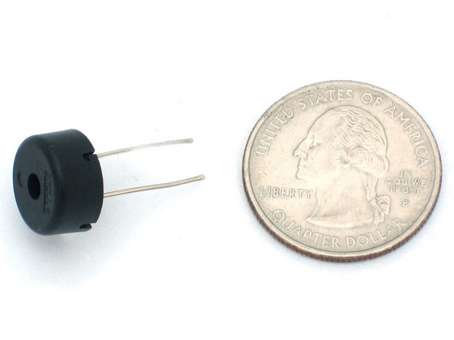
Piezo Buzzer
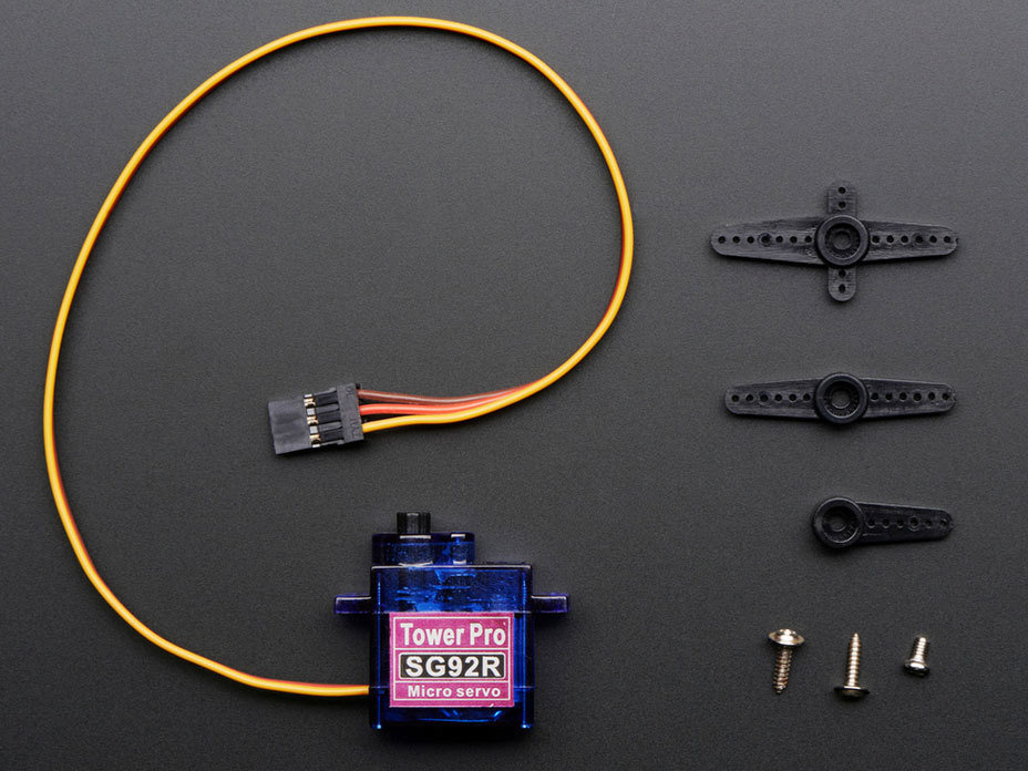
Micro Servo Motor
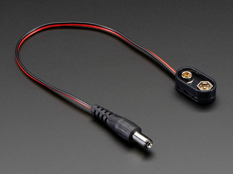
9V Clip
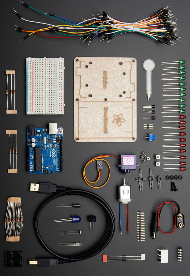
Additional Components
A - 10mm Blue LED (x1)
B - Toy DC Motor (x1)
C - 8-Bit Shift Register (74HC595) (x1)
D - Pushbuttons (x2)
E - Potentiometer (10k) (x1)
F - Relay (5v DPDT) (x1)
G - Transistors (P2N2222A) (x2)
H - Diodes (1N4001) (x2)
A
E
B
C
D
F
G
H

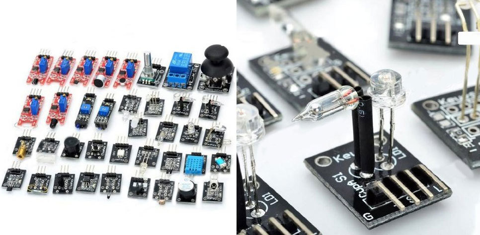
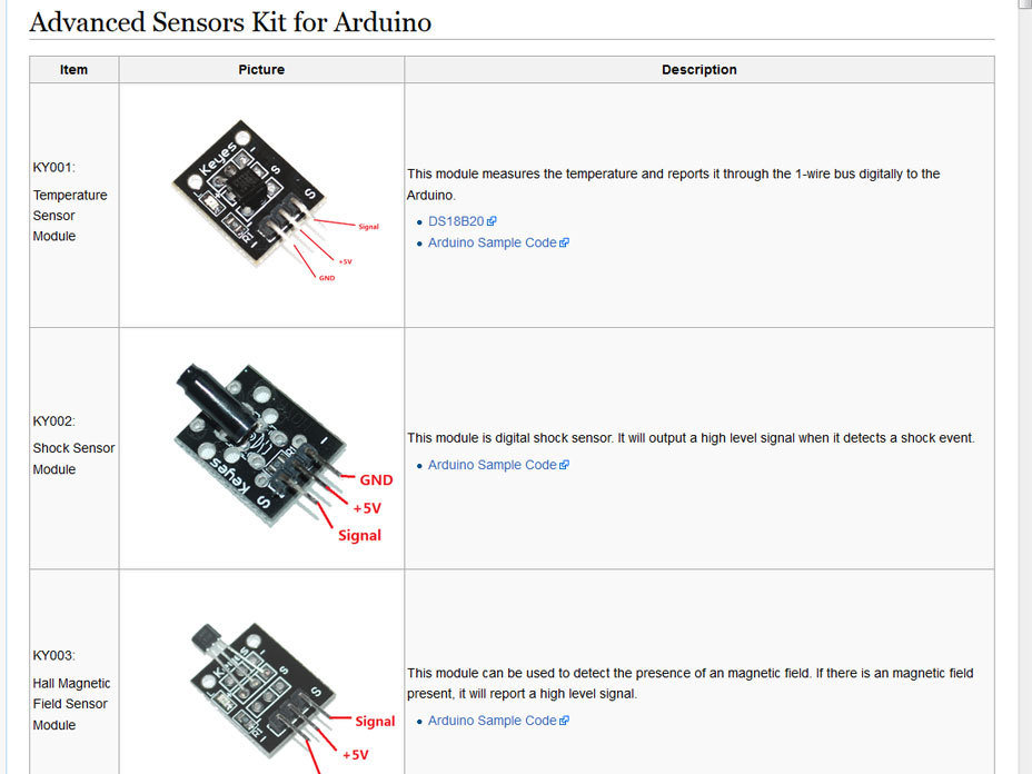
ADVANCED SENSORS KIT FOR ARDUINO
Sensors Included:
- Small passive buzzer KY-006
- 2-color LED KY-011
- Hit sensor KY-031
- Vibration switch KY-002
- Photo resistor KY-018
- Key switch KY-004
- Tilt switch KY-020
- 3-color full-color LED SMD s KY-009
- Infrared emission sensor KY-005
- 3-color LED KY-016
- Mercury open optical switch KY-017
- 2-color LED 3MM KY-029
- Active buzzer KY-012
- Temperature sensor KY-013
- Automatic flashing colorful LED KY-034
- Mini magnetic reed s KY-021
- Hall magnetic sensor KY-003
- Infrared sensor receiver KY-022
- Class Bihor magnetic sensor KY-035
- Magic light cup KY-027
- Rotary encoder KY-040
- Optical broken KY-010
- Detect the heartbeat KY-039
- Reed KY-025
- Obstacle avoidance sensor KY-032
- Hunt sensor KY-033
- Microphone sound sensor KY-038
- Laser sensor KY-008
- 5V relay KY-019
- Temperature sensor KY-001
- Digital Temperature sensor KY-028
- Linear magnetic Hall sensors KY-024
- Flame sensor KY-026
- Sensitive microphone sensor KY-037
- Temperature and humidity sensor KY-015
- XY-axis joystick KY-023
- Metal touch sensor KY-036
ELECTRONICS 101
Electricity
Voltage (Volts)
Current (Amps)
Resistance (Ohms)
Circuit
Short Circuit
Parallel vs Serial Circuit
Multimeter
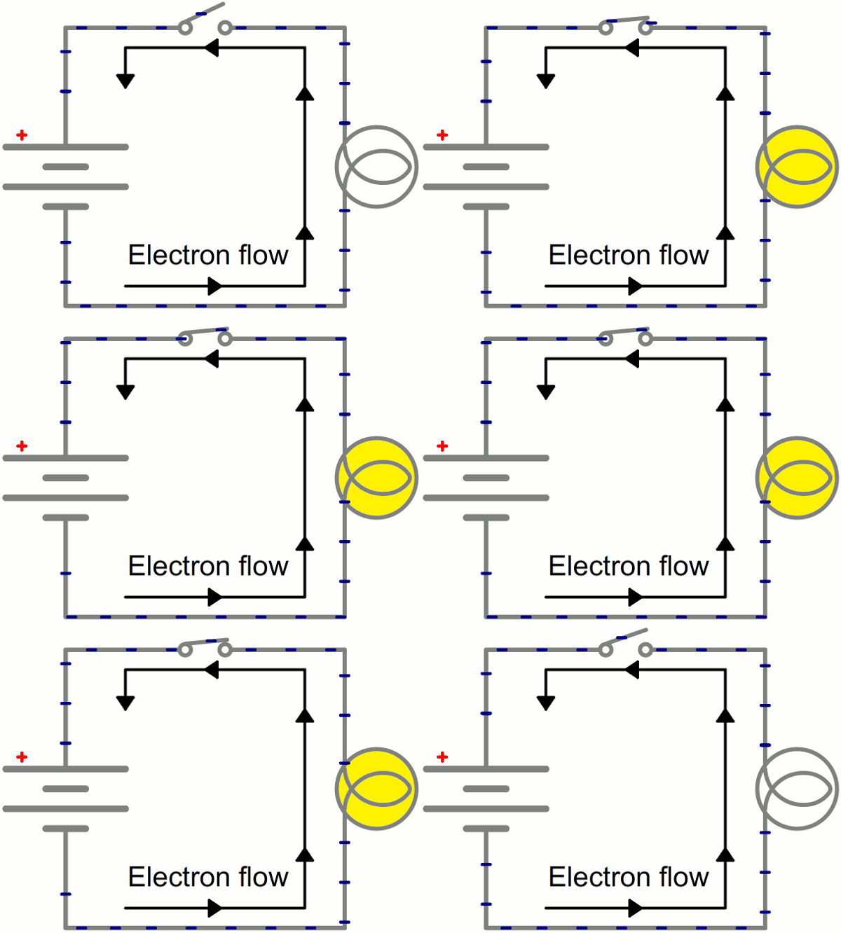
Electricity
is the flow of electric charge.
Charge comes in two types:
(+) Positive
(-) Negative
In order for electricity to work, it needs to move (flow).
It needs a path to flow - usually through a conductor.
GIF from Electricity Tutorial from Sparkfun
Electricity
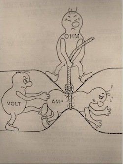
Electricity has these three basic principles:
Voltage (volt)
the difference in charge between two points
Current (amp)
the rate at which the charge is flowing
Resistance (ohm)
the material's resistance to the flow of the charge/current.
Voltage
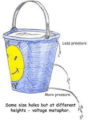
Volts are the unit of measurement.
Electricity wants to flow from a higher voltage to a lower voltage.
Electricity Tutorial from Sparkfun
Current
Amps are the unit of measurement.
Electricity wants to flow from a higher voltage to a lower voltage.
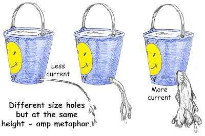
Circuit
Amperage or Amps are the unit of measurement.
Electricity wants to flow from a higher voltage to a lower voltage.
Technological mandala 2 (The beginning), 2012

Short Circuit
is a faulty or accidental connection between two points in an electric circuit, which bypasses the load and establishing a path of lesser resistance through which an excessive current can flow.
It can cause damage to the components if the circuit is not protected by a fuse
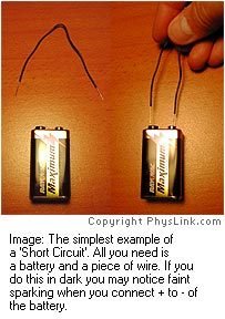
Parallel Circuit
In a parallel circuit, each component is electrically connected to the source at the same point and each component gets the full voltage simultaneously.
If one goes out, the rest stay lit.
Series Circuit
In a series circuit, current must pass through one component to get to the next component.
Voltage is divided between them which means they get dimmer the further into the circuit.
Also if one component goes out, they all go out.
Think old Christmas lights.
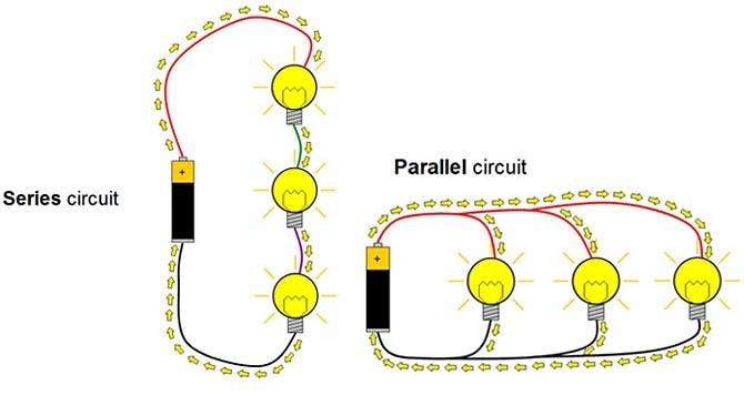
Series Circuit vs. Parallel Circuit
Multimeter
An electronic measuring instrument. It can measure voltage, current, and resistance.
It can be used for basic fault finding in circuits and for troubleshooting electrical problems in electronic devices.


Breadboard 101
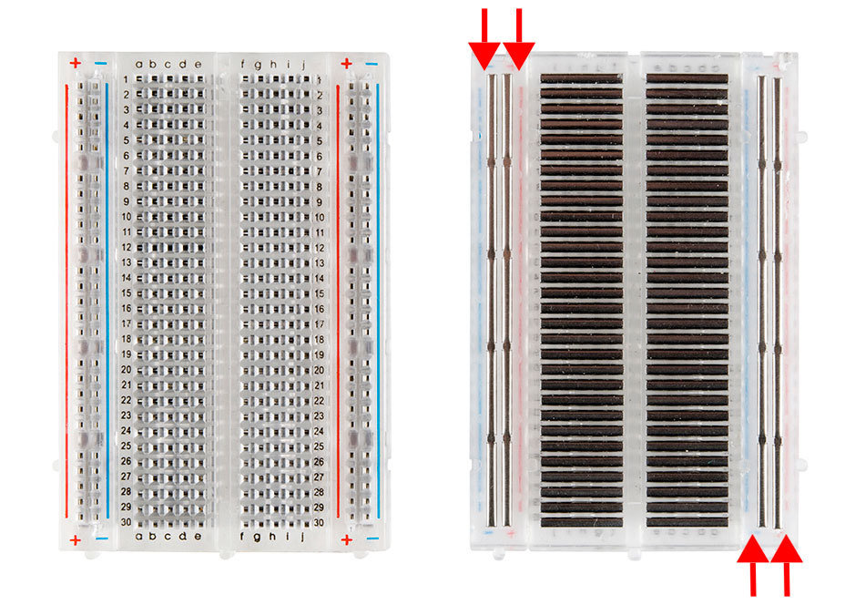
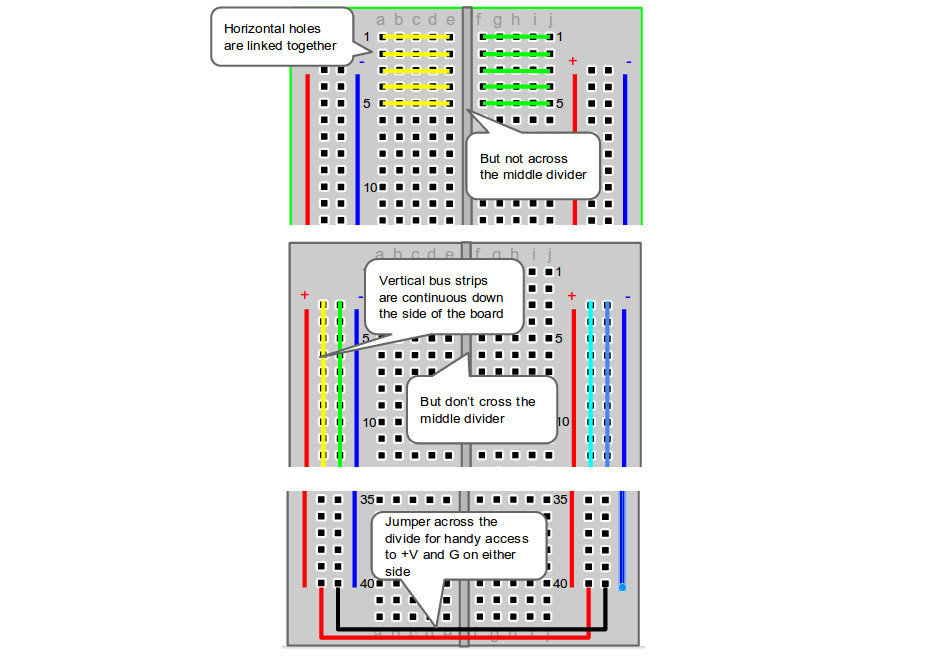
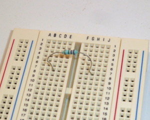
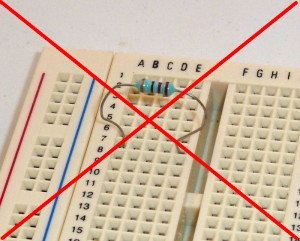
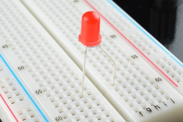
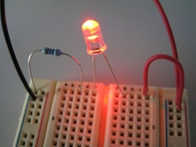
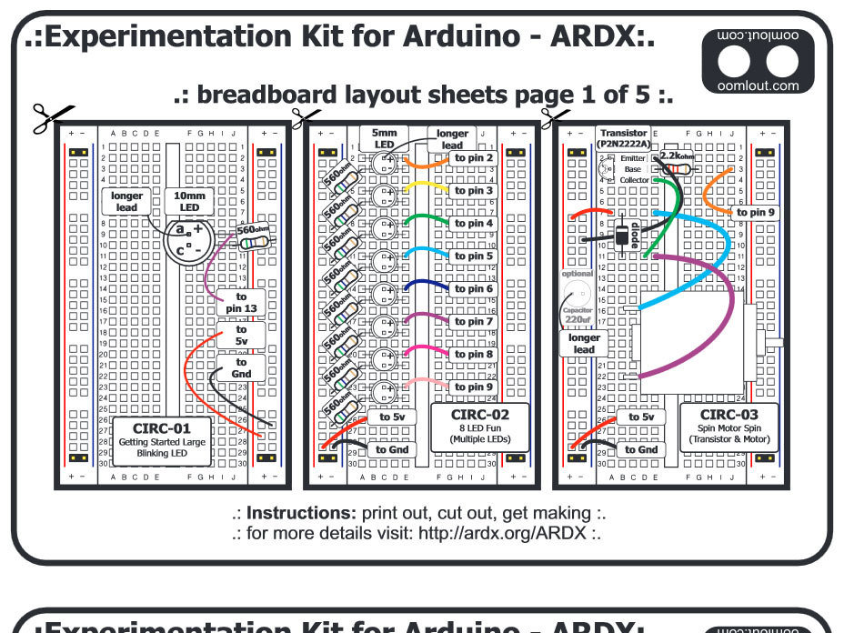
Here you can see a regular LED circuit across the breadboard. The red equals the positive and black equals the negative that goes to either a battery or power supply. The Arduino LED circuit has one slight difference: an additional cable to connect it to the Arduino.

Arduino 101


Arduino Uno | ATmega328
ARDUINO SPECS (Link)
-
Microcontroller ATmega328
-
Operating Voltage5V
-
Input Voltage 7-12V (recommended)
-
Input Voltage 6-20V (limits)
-
Digital I/O Pins14 (of which 6 provide PWM output)
-
Analog Input Pins6
-
DC Current per I/O Pin40 mA
-
DC Current for 3.3V Pin50 mA
-
Flash Memory 32 KB (ATmega328) of which 0.5 KB used by bootloader
-
SRAM 2 KB (ATmega328)
-
EEPROM 1 KB (ATmega328)
-
Clock Speed 16 MHz
USB
Each of the 14 digital pins on the Uno can be used as an input or output, using pinMode(), digitalWrite(), and digitalRead() functions.
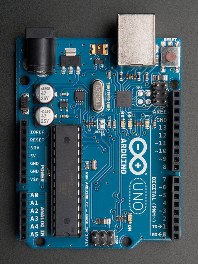
External Power
Each of the 14 digital pins on the Uno can be used as an input or output, using pinMode(), digitalWrite(), and digitalRead() functions.

Power pins
Each of the 14 digital pins on the Uno can be used as an input or output, using pinMode(), digitalWrite(), and digitalRead() functions.

Input/Output Pins
Each of the 14 digital pins on the Uno can be used as an input or output, using pinMode(), digitalWrite(), and digitalRead() functions.

Analog/Digital
Each of the 14 digital pins on the Uno can be used as an input or output, using pinMode(), digitalWrite(), and digitalRead() functions.


Arduino Programming
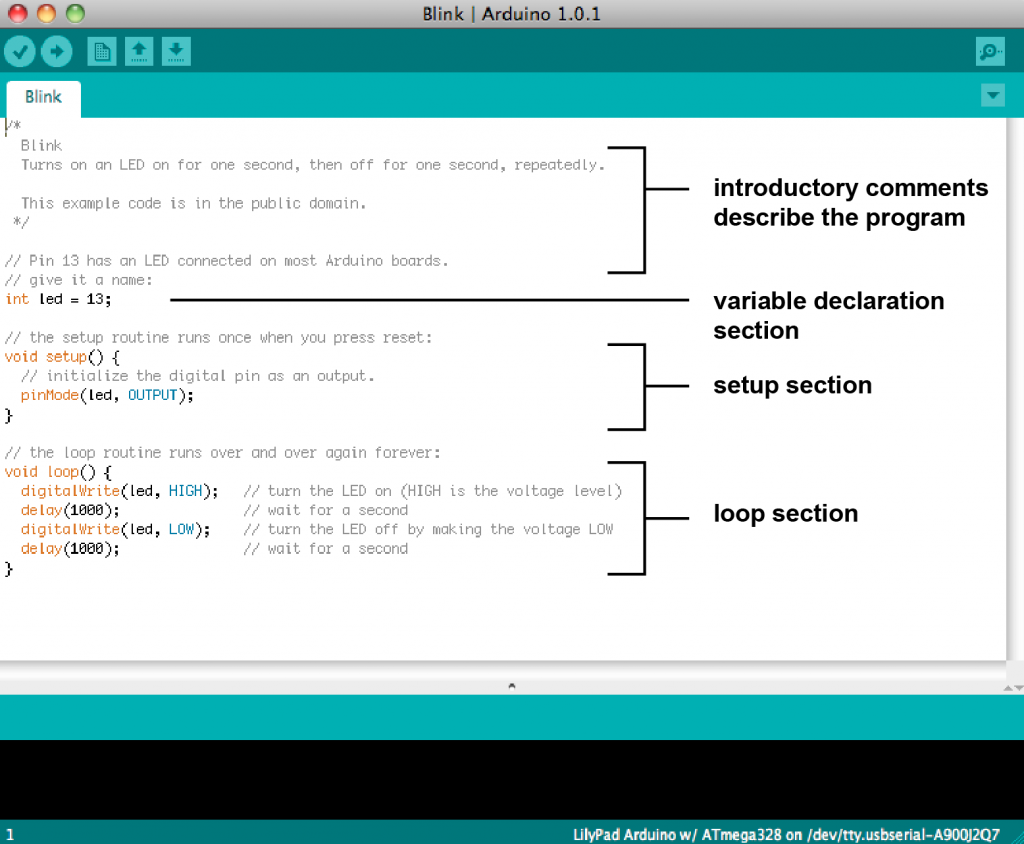
Arduino Sketch
Bring on the Bling!
Your First Circuit
Components
- Red wire (+)
- Black wire (-)
- White wire (input to Arduino Pin)
- LED (Red or Green)
- Resistor
LED
LEDs have a positive and negative end.
LEDs require a resistor or they will burn themselves out.
Different LEDs use different Voltages.
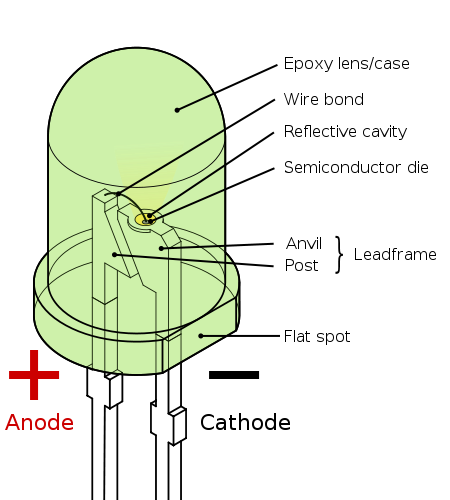
How to tell
(+) from (-)
- Check the length of the leads – the long one is positive, the short one is negative
- Feel around the rim of the bulb – there will be a flat edge above the negative lead.
- Look inside the bulb at the actual semiconductors. The large, wide piece is connected to the negative lead and the short, skinny piece is connected to the positive lead.

Make It Interactive!
Let's add a button
Image Credits
Arduino Images from Adafruit.com
Breadboard Images from Adafruit.com
Mounting Plate from Adafruit.com
Jumper Wires from Adafruit.com
USB Cable from Adafruit.com
9V Battery Clip from Adafruit.com
Micro Servo Motor from Adafruit.com
Force Sensitive Resistor from Adafruit.com
ARDUINO WORKSHOP
By //benitez_vogl
ARDUINO WORKSHOP
Arduino Workshop | February 4 2015
- 1,085


