An Introduction to Millimeter-Wave
Mobile Broadband Systems

Yung-Sheng Lu

AUG 02, 2017

@NCTU-CS

Written by Zhouyue Pi and Farooq Khan, Samsung Electronics.

Publish on IEEE Communications Magazine, JUN 2011.

Outline

  • Foreword

  • Introduction

  • Millimeter-wave Spectrum

  • Millimeter-wave Propagation

  • MMB Network Architecture

  • MMB Air Interface Design

  • Conclusion

Foreword

Foreword

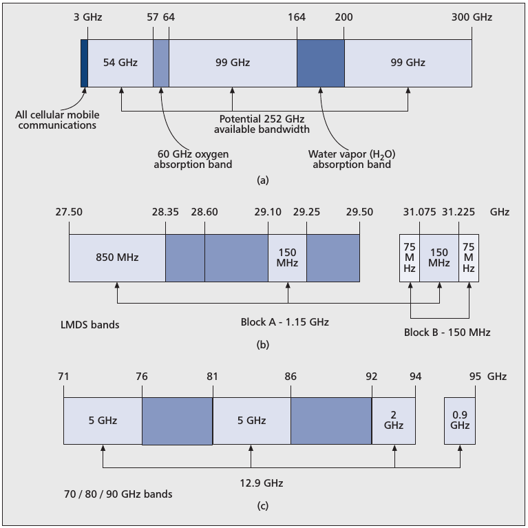
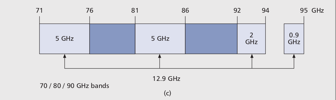
  • Why should start looking at the 30-300 GHz spectrum for mobile broadband applications?

    • ​Bandwidth
       

  • Millimeter-wave mobile broadband (MMB) system is a candidate next-generation mobile communication system.

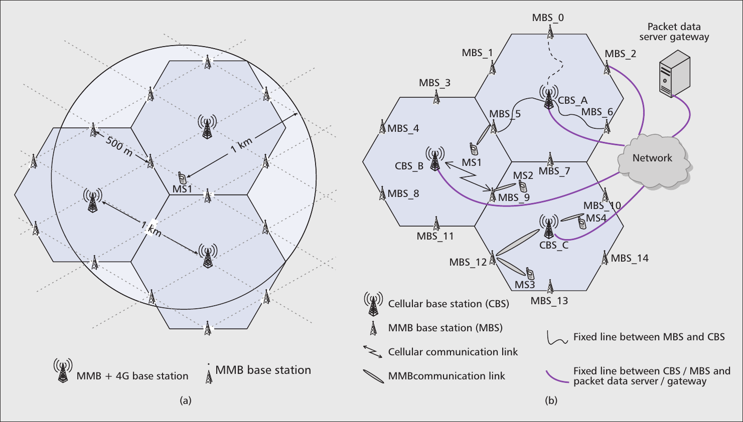
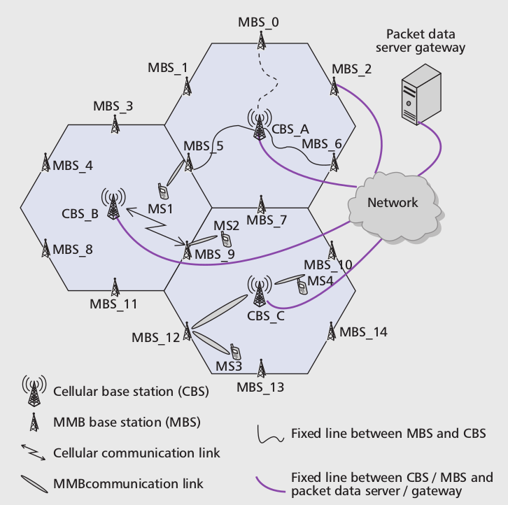
    • MMB network architecture
       

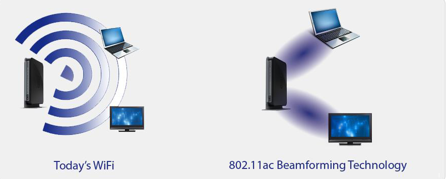
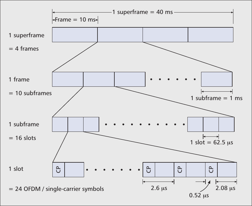
  • Beamforming techniques and the frame structure of the MMB air interface​

Introduction

4G Systems

  • Already achieves spectral efficiency close to bits per second per Hertz per cell

    • Orthogonal frequency-division multiplexing (OFDM)

    • Multiple-input multiple-output (MIMO)

    • Multi-user diversity

    • Link adaptation

    • Turbo code

    • Hybrid automatic repeat request (HARQ)

4G Systems (cont.)

  • Due to the limited room for further spectral efficiency imporvement, increasing capacity per geographic area is imperative.
     

  • The capacity can only scale linearly with the number of cells.

Millimeter-wave

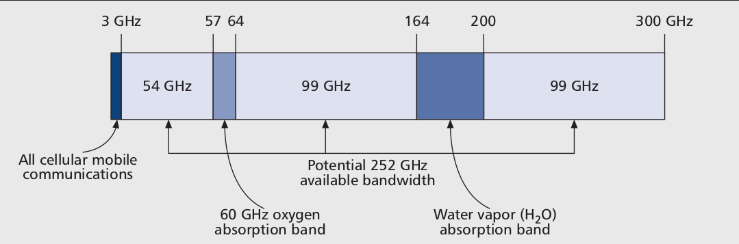
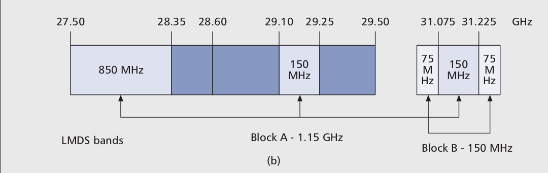
  • A vast amount of spectrum in the 3–300 GHz range remains underutilized.

Millimeter-wave (cont.)

  • Millimeter-wave communication systems can achieve point-to-point communication at multi-gigabit data rates in a few kilometers distance under some constraints.

  • The 60 GHz band as unlicensed spectrum has spurred interest in gigabit-per-second short-range wireless communication.
     

  • Several industrial standards have been developed.

    • ​e.g., ECMA-387, IEEE 802.15.3c, IEEE 802.11ad.

Millimeter-wave Spectrum

Unleashing the 3-300 GHz Spectrum

  • The 300 MHz-3 GHz band is referred to as the sweet spot.
  • The portion above 3 GHz has been explored for short-range and fixed wireless communication.
  • The 28-30 GHz band - Local multipoint distribution service (LMDS)
  • Up to 252 GHz can potentially be used in MMB.

LMDS and 70/80/90 GHz Bands

  • Use a cellular infrastructure with multiple base stations
  • The Federal Communications Commission (FCC) auctioned two LMDS licenses per market (basic trading areas).
    • The A license (1.15 GHz)
    • The B license (150 MHz)
  • The E-band is available to ultra-high-speed data communication.​​
    • Point-to-point wireless local area networks
    • Mobile backhaul
    • Broadband Internet
    • Highly directional “pencilbeam” signal

LMDS and 70/80/90 GHz Bands (cont.)

Millimeter-wave Propagation

Free-space Propagation

  • Misconception
    Transmission loss of millimeter wave is accounted for principally by free space loss.
  • Free-space propagation loss depends on frequency.
    • Free-space path loss formula

       
    • Free-space path loss in decibels
L = { \left( \frac{4 \pi d}{\lambda} \right) } ^ 2 = { \left( \frac{4 \pi d f}{c} \right) }^ 2
L=(4πdλ)2=(4πdfc)2L = { \left( \frac{4 \pi d}{\lambda} \right) } ^ 2 = { \left( \frac{4 \pi d f}{c} \right) }^ 2
L(dB) = 10 \log_{10} \left( {\left( \frac{4 \pi d}{\lambda} \right)} ^ 2 \right) = 20 \log_{10} \left( \frac{4 \pi d f}{c} \right)
L(dB)=10log10((4πdλ)2)=20log10(4πdfc)L(dB) = 10 \log_{10} \left( {\left( \frac{4 \pi d}{\lambda} \right)} ^ 2 \right) = 20 \log_{10} \left( \frac{4 \pi d f}{c} \right)
= 20 \left( \log_{10}(d) + \log_{10}(f) \right) -147.55
=20(log10(d)+log10(f))147.55= 20 \left( \log_{10}(d) + \log_{10}(f) \right) -147.55

Free-space Propagation (cont.)

  • An antenna with a larger aperture has larger gain than a smaller one as it captures more energy from a passing radio wave.
    • Dependency of antenna aperture from antenna gain


  • Large numbers of antennas enable transmitter and receiver beamforming with high gains.
A = G \frac{\lambda ^ 2}{4 \pi }
A=Gλ24πA = G \frac{\lambda ^ 2}{4 \pi }

Penetration and Other Losses

  • Atmosphere gaseous losses and precipitation attenuation are typically less than a few dB per kilometer in 3-300 GHz.
     
  • The loss due to reflection and diffraction depends greatly on the material and the surface.
    • non-line-of-sight (NLOS) communication
       
  • While signals at lower frequencies can penetrate more easily through buildings, millimeter-wave signals do not penetrate most solid materials very well.

Penetration and Other Losses (cont.)

Doppler and Multipath

  • The Doppler of a wireless channel depends on the carrier frequency and mobility.
    • The narrow beams at the transmitter and receiver will significantly reduce angular spread of the incoming waves.
       
  • ​As the incoming waves are concentrated in a certain direction, there will be a non-zero bias in the Doppler spectrum.
     
  • With narrow transmitter and receiver beams, the multipath components of millimeter waves are limited.

MMB Network Architecture

A Standalone MMB Network

  • In order to ensure good coverage, MMB base stations need to be deployed with higher density than macrocellular base stations.

A Standalone MMB Network (cont.)

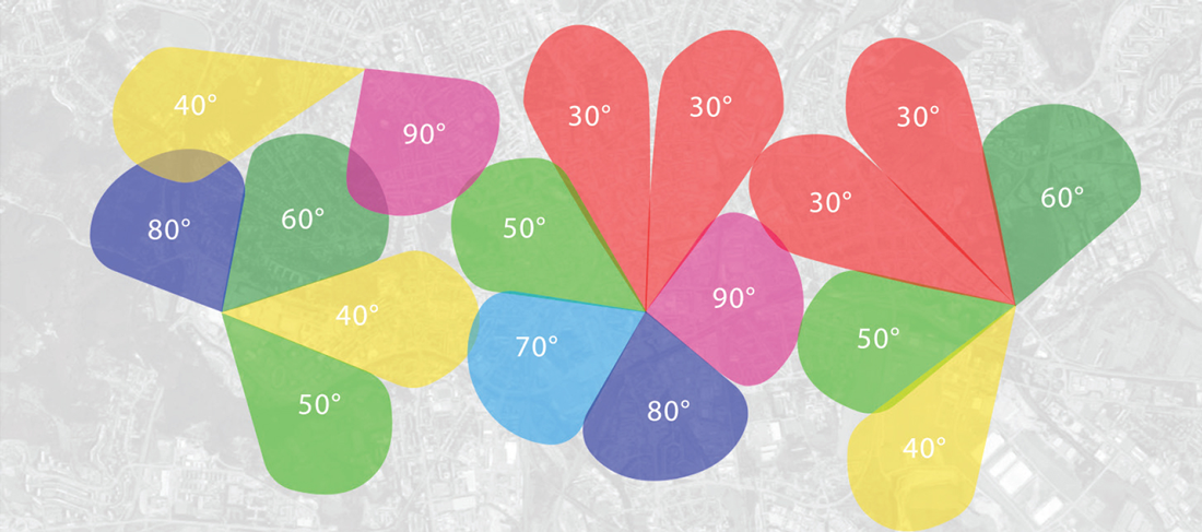
  • The transmission and/or reception in an MMB system are based on narrow beams.

    • Suppress the interference from neighboring MMB base stations
    • Extend the range of an MMB link
       
  • Allows significant overlap of coverage among neighboring base stations

A Standalone MMB Network (cont.)

  • With the high density of MMB base stations, the cost to connect every MMB base station via a wired network can be significant.
    • ​Allow some MMB base stations to connect to the backhaul via other MMB base stations.
       
  • Due to large beamforming gains, the MMB inter-BS backhaul link can be deployed in the same frequency as the MMB access link without causing much interference.

A Standalone MMB Network (cont.)

  • The low efficiency of RF devices such as power amplifiers and multi-antenna arrays with current technology. ​
    • Use fixed beams or sectors with horn antennas.
    • The mobile station receiver needs to use a multi-antenna array to form a beamforming pattern toward the base station.

Hybrid MMB + 4G Systems

  • Improves coverage and ensure seamless user experience
     
  • Make the entire millimeter-wave spectrum available for data communication.

MMB Air Interface Design

Beamforming

  • Beamforming is a signal processing technique used for directional signal transmission or reception.
     
  • Spatial selectivity/directionality is achieved by using adaptive transmit/receive beam patterns.

Beamforming (cont.)

  • Beamforming is a key enabling technology of MMB.
    • For MMB transceivers, the small size (         dipoles) and separation (also around         ) of millimeter-wave antennas allow a large number of antennas and thus achieve high beamforming gain in a relative small area.
    • Spatial-division multiple access (SDMA)
\lambda / 2
λ/2\lambda / 2
\lambda / 2
λ/2\lambda / 2

Beamforming (cont.)

  • Challenges
    • The cost of implementing one RF chain per antenna
       
    • Battery power consumption
       
    • Reduce the cost and complexity of mobile stations

Frame Structure

  • MMB uses OFDM and single-carrier waveform for largely the same reasons between multiplexing schemes of 4G systems.

Frame Structure (cont.)

  • The OFDM/single-carrier numerology is carefully chosen according to a number of engineering considerations.

    • ​The sampling rate is chosen to be a multiple of 30.72 MHz.

    • The cyclic prefix (CP) is chosen to be 520 ns

    • The subcarrier spacing is chosen to be 480 kHz.

Frame Structure (cont.)

  • MMB supports transmission with single-carrier waveform.
    • Single-carrier waveform has lower peak-to-average-power(PAPR) than OFDM.

    • A lower PAPR allows the receiver to use a low-resolution analog-to-digital converter (ADC).

註:峰值因數 (Peak-to-average ratio; PAR)

和波形有關的無因次量,為波形的振幅再除以波形 RMS (time-averaged) 所得到的值。

R_{peak\ to\ avg} = \frac { |x|_{peak} } { x_{rms} }
Rpeak to avg=xpeakxrmsR_{peak\ to\ avg} = \frac { |x|_{peak} } { x_{rms} }

註:峰均功率比 (Peak-to-average power ratio; PAPR)

為振幅平方 (表示峰值功率) 除以 RMS 平方 (表示平均功率) 的比值。

R_{peak\ to\ avg\ power} = \left( \frac{ {|x|_{peak}} }{ {x_{rms}} } \right) ^ 2 = C ^ 2
Rpeak to avg power=(xpeakxrms)2=C2R_{peak\ to\ avg\ power} = \left( \frac{ {|x|_{peak}} }{ {x_{rms}} } \right) ^ 2 = C ^ 2

Link Budget

  • Determine the downlink link budget of an MMB system

    • Base station transmission power

    • Transmitter and receiver beamforming gains
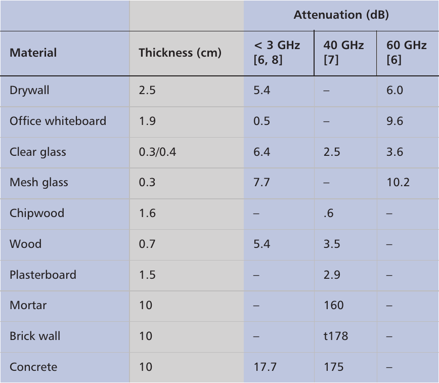
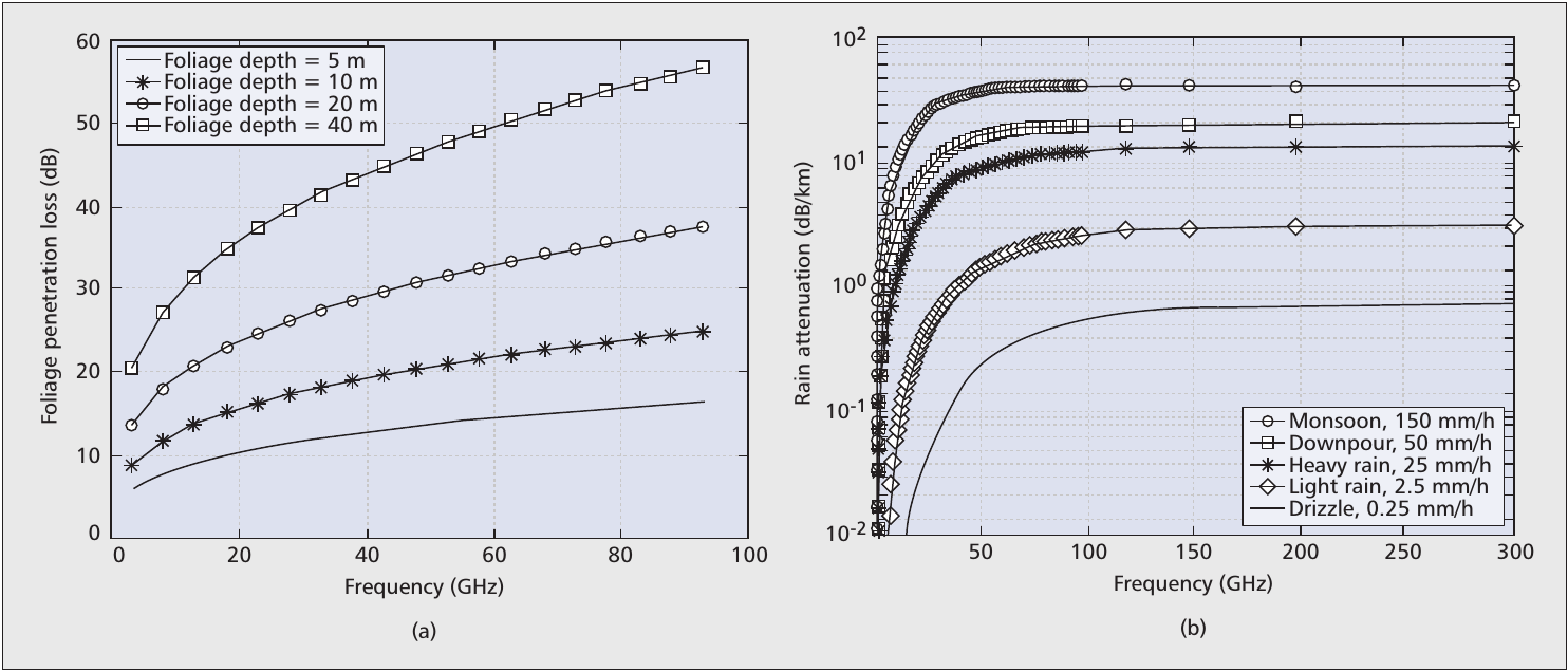
    • Path loss

Conclusion

Conclusion

  • Millimeter-wave spectrum can potentially provide the bandwidth required for mobile broadband applications for the next few decades and beyond.
     
  • The narrow beam width of MMB transmissions
     
  • The MMB base stations form a grid.
     
  • The inter-BS backhaul link can be used to mitigate the cost of backhauling (and to expedite deployment).

Conclusion (cont.)

  • In order to operate in an urban mobile environment while keeping a low overhead, we chose the MMB subcarrier spacing to be 480 kHz and the CP to be 520 ns.

  • Design the frame structure to facilitate hybrid MMB + 4G operation.

  • In the link budget analysis, a 2 Gb/s data rate is achievable at 1 km distance with millimeter waves in an urban mobile environment.

References

References

An Introduction to Millimeter-Wave Mobile Broadband Systems

By David Lu

An Introduction to Millimeter-Wave Mobile Broadband Systems

An Introduction to Millimeter-Wave Mobile Broadband Systems

  • 1,597