Tour Through the Graphics Pipeline
Overview:
- Authorship, Data, and Import
- Vertex and Index Buffer Objects
- Uniforms: Matrix Transformations and Texture Binding
- Shader Pipeline
Authorship and Data Import
- Source files for what we want to render
- Several options for export:
- Established file formats
- OBJ, FBX, COLLADA, etc.
- Or in-house format
- BSP, or some plugin .dll or script to export from
- Established file formats
- The tour answers this question:
- "How do we get a bunch of vertices from a saved file on disk to 3D space rasterized onto a 2D screen?"
- Lots of answers depending on specifics
- Large scenes, small props, animated, static, lighting
# Blender v2.65 (sub 0) OBJ File
# www.blender.org
o teapot.005
v -0.498530 0.712498 -0.039883
v -0.501666 0.699221 -0.063813
v -0.501255 0.717792 0.000000
v -0.624036 0.711938 -0.039883
v -0.526706 0.651362 -0.039883
v -0.508714 0.682112 -0.071712
v -0.622039 0.698704 -0.063813
v -0.624834 0.717232 0.000000
v -0.498530 0.712498 0.039883
v -0.638129 0.287158 0.000000
v -0.517593 0.664661 -0.063813
v -0.534329 0.646030 0.000000
v -0.614850 0.651067 -0.039883
# etc. and so on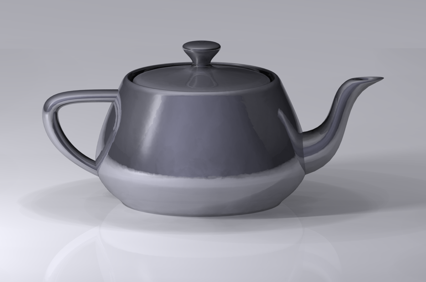
<= into =>
http://www.sjbaker.org/wiki/index.php?title=The_History_of_The_Teapot
Possible vertex data includes:
- 3D position (mandatory!)
- Textures and texture coordinate vertex data
- Diffuse, lightmap, normal, heightmap, etc.
- Vertex normals
- Bone weights and bone indices
- For animated models
//parse from disk and translate to this:

struct Vertex
{
    float32[4] position;
    float32[2] diffuseTexCoord;
    //and/or other TexCoords
    int32[4] boneIndices;
    float32[4] boneWeights;
}

//...

auto vertices = std::vector<Vertex>(NUM_VERTICES);
Buffer Objects
- Recap: from disk to Vertex struct
- Next step: upload to GPU
- Two kinds of buffers represent a single mesh:
- Vertex Buffer - straight copy of Vertex array
- Index Buffer - orders Vertices into trios of Triangles
Why Index Buffers?
- Storage space
- Concept of unique, non-redundant vertices
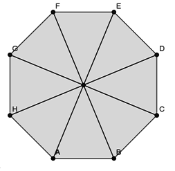
- Consider this octagon
- Drawn with triangles, we have 9 unique vertices
- A, B, C, D, E, F, G, H, I
- GPU expects triangle list
- AIB, BIC, CID, DIE, EIF, etc.
- Without index buffer, storage space inflates massively
I
Matrix Transformations
- Digging deep into linear algebra now: a vector ONLY makes sense within the context of a coordinate system
- Able to apply different kinds of transformations
- Translate, Rotate, Scale
- Concept of "spaces":
- Relative origin point for 3D objects and scenes, coordinate system
- Four major Spaces:
- Model, World, View, Projection
Additional reading:
http://www.codinglabs.net/article_world_view_projection_matrix.aspx
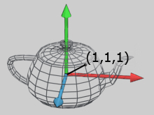
- Model Space
- Vertices only in context of single model
- 3D author/artist programs deal with this
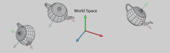
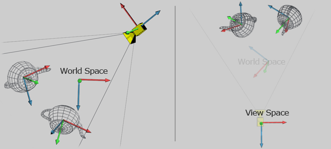
- World Space
- Whole models in relation to a scene in 3D space
- View Space
- World space, but transformed to a 'camera'
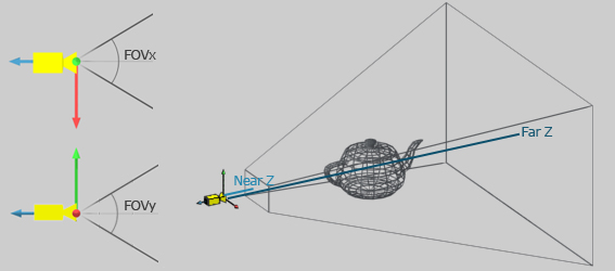
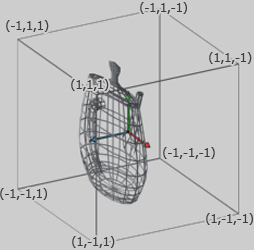
- Projection Space
- View space flattened to map 3D vertices to 2D polygons
- Current part of the pipeline deals with World Space
- Good way to organize more complex systems is with a Scene graph
- Tree of nodes, where nodes have World transformation and/or mesh
- When rendering a mesh, multiply transform matrices all the way to root
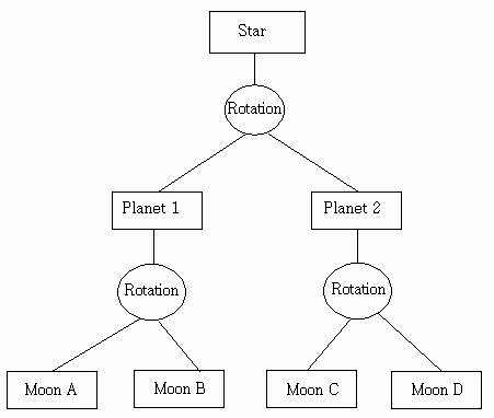
- To render Moon B:
- multiply the transformation matrices starting with Star
- times Planet 1's translation and rotation relative to Star
- then Moon B's translation and rotation relative to Planet 1
Draw Calls and Shading
- Tons of API calls to set up a final call to draw a mesh with certain state:
- Currently bound Vertex Buffer
- Currently bound Object Buffer
- Textures bound to read from
- Current final transformation matrix from Model to World space
- Another matrix for World space to Projection space
- Current shader program
- Vertex and Fragment steps at minimum, other steps optional
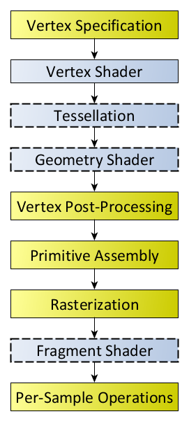
Shader pipeline
- Blue boxes are programmable and customizable
- Yellow boxes are defined on GPU hardware
- Aim for minimal code size and complexity
- If repeatedly doing same action in later stage of pipeline, move it to earlier stage
- Or back up to CPU side
Vertex Shader
- Input: that giant list of Vertices we had earlier in Model space
- Output: a transformed list of vertices to Projection space
- doesn't need to match input format exactly
#version 410
#Example OpenGL vertex shader

layout (std140) uniform Matrices {        #transformation matrices,
    mat4 projModelViewMatrix;             #output from earlier scene graph
    mat3 normalMatrix;
};

in vec3 position;       #mirrors whatever vertex format you had
in vec3 normal;
in vec2 texCoord;

out VertexData {        #"Varying" interpolated attributes in vertex-to-fragment stage
    vec2 texCoord;
    vec3 normal;
} VertexOut;

void main()
{
    VertexOut.texCoord = texCoord;
    VertexOut.normal = normalize(normalMatrix * normal);
    gl_Position = projModelViewMatrix * vec4(position, 1.0);
}
In-between
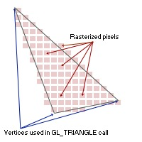
- GPU rasterizes triangles to fragments/pixels
- Position mandatory
- Projection/Clip space, remember!
- And other attributes specified in vertex shader
- Position mandatory
Fragment Shader
- Input: Fragments from rasterization stage and varying data
- Output: Final pixel to screen
#version 410
#Simple diffuse texture mapping fragment shader

varying vec2 diffuseTexCoord;

uniform sampler2D diffuseTexture;

void main()
{
    gl_FragColor = texture2D(diffuseTexture, diffuseTexCoord.st);
}
Tour Through the Graphics Pipeline
By tdhoward


