G Code and Slicers

Knox3DP
2 November 2016


Tonight
- Let's Talk G Code
- Slicers
- Peter Shankles - writing a slicer tool for microfluidics
history of g-code
- First developed in late '50s by MIT
- 1970s - '90s, industry standardized around
- '80s when printers began, followed along with NC standards

Common commands
- G
- F
- T
- I / J / (K)
- M
- Tells what motion is wanted or offset value
- Sets feedrate
- Tool selection (in CAM)
- Arc Center in X / Y / (Z)
- Special commands (like SD card)
- G00
- G01
- G02
- G17
- G20
- G90
- G92
- Rapid positioning (max speed)
- Linear interpolation
- Circular interpolation (cw, G03 - ccw)
- XY Plane Selection (G18 - XY, G19 - YZ)
- Set units in inches (G21 - mm)
- Absolute positioning (G91- incremental)
- Feedrate per minute (G94 - per revolution)


example
- Initialization
- seeking z-axis to 0.25", travel to (-0.5,0,0.1)
- Drop z to 0, begin slow feed rate and draw circle
- Finish, lift Z up, then seek back to (0,0,0.25)

G17 G20 G90 G94 G54
G0 Z0.25
X-0.5 Y0.
Z0.1
G01 Z0. F5.
G02 X0. Y0.5 I0.5 J0. F2.5
X0.5 Y0. I0. J-0.5
X0. Y-0.5 I-0.5 J0.
X-0.5 Y0. I0. J0.5
G01 Z0.1 F5.
G00 X0. Y0. Z0.25
How to get from cad to g-code
- G-code is extremely precise, at a cost of length
- A slicer is used to interpret CAD file (maybe just STL), and convert to G-Code
- Needs information about
machine for translation
- Needs information about
G17 G20 G90 G94 G54
G0 Z0.25
X-0.5 Y0.
Z0.1
G01 Z0. F5.
G02 X0. Y0.5 I0.5 J0. F2.5
X0.5 Y0. I0. J-0.5
X0. Y-0.5 I-0.5 J0.
X-0.5 Y0. I0. J0.5
G01 Z0.1 F5.
G00 X0. Y0. Z0.25
circle(d = 1);
How to get from cad to g-code Example


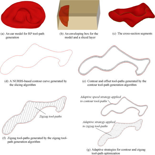
G.Q. Jin, W.D. Li, C.F. Tsai, L. Wang, Adaptive tool-path generation of rapid prototyping for complex product models, Journal of Manufacturing Systems, Volume 30, Issue 3, August 2011, Pages 154-164, ISSN 0278-6125, http://dx.doi.org/10.1016/j.jmsy.2011.05.007
Slicing
Peter Shankles

knox3dp-meeting-five
By Alex Pawlowski
knox3dp-meeting-five
- 942


