Introduction to
ARDUINO
Alison Hall
Agenda
-
What is Arduino?
-
Arduino Devices
-
Circuit Basics
-
Analog vs. Digital
-
Coding
-
Getting Started
-
Examples
-
Creating custom Arduino setups
- Additional Features
What is Arduino?
1
What is Arduino?
Arduino is a tool for making computers that can sense and control more of the physical world than your desktop computer. It's an open-source physical computing platform based on a simple microcontroller board, and a development environment for writing software for the board.
Arduino can be used to develop interactive objects, taking inputs from a variety of switches or sensors, and controlling a variety of lights, motors, and other physical outputs. Arduino projects can be stand-alone, or they can communicate with software running on your computer (e.g. Flash, Processing, MaxMSP.) The boards can be assembled by hand or purchased preassembled; the open-source IDE can be downloaded for free.
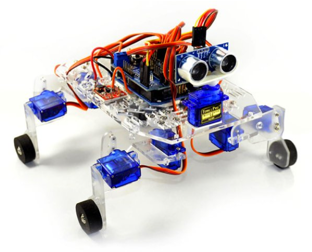
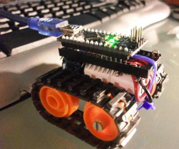
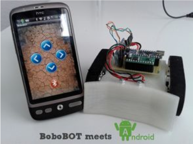
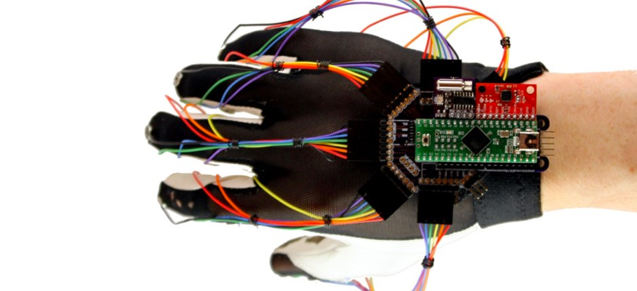
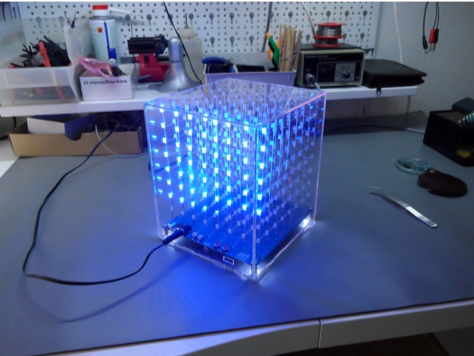
Projects
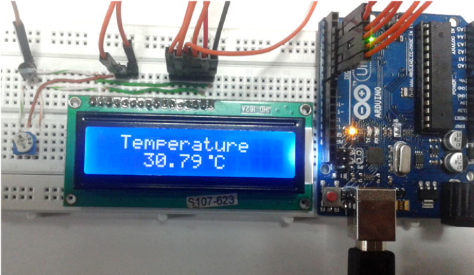
Inputs and Outputs
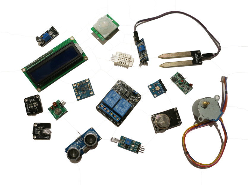
Inputs/Sensors:
- Motion
- Light
- Moisture
- Infrared
- Tilt
- Pressure
- Sound
- etc.
Outputs:
- LED
- Motor
- LCD display
- Sound
- etc.
Getting components
- Creatron Inc. - a store near College & Bathurst (https://www.creatroninc.com/)
- SparkFun - online store (https://www.sparkfun.com/)
- Adafruit - online store (https://www.adafruit.com/)
- Amazon, etc.
Arduino Devices
2
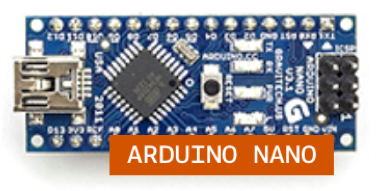
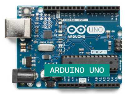
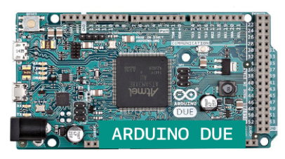
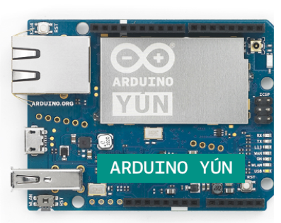
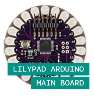
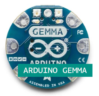
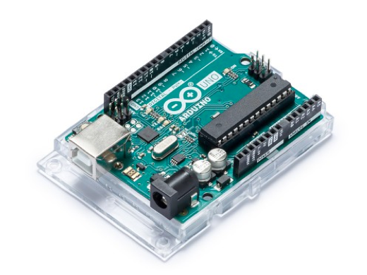
Some Arduino Boards
Arduino Specifications
|
Name |
Processor |
Operating/Input Voltage |
CPU Speed |
Analog In/Out |
Digital IO/PWM |
EEPROM [kB] |
SRAM [kB] |
Flash [kB] |
USB |
UART |
Type |
|
ATmega328P |
5 V / 7-12 V |
16 MHz |
6/0 |
14/6 |
1 |
2 |
32 |
Regular |
1 |
Generic |
|
|
ATmega168V ATmega328P |
2.7-5.5 V / 2.7-5.5 V |
8MHz |
6/0 |
14/6 |
0.512 |
1 |
16 |
- |
- |
Wearable |
|
|
ATtiny85 |
3.3 V / 4-16 V |
8 MHz |
1/0 |
3/2 |
0.5 |
0.5 |
8 |
Micro |
0 |
Wearable |
|
|
ATSAM3X8E |
3.3 V / 7-12 V |
84 MHz |
12/2 |
54/12 |
- |
96 |
512 |
2 Micro |
4 |
Upgraded |
|
|
ATmega32U4 AR9331 Linux |
5 V |
16 MHz 400MHz |
12/0 |
20/7 |
1 |
2.5 16MB |
32 64MB |
Micro |
1 |
Upgrade |
Arduino Uno 3
The UNO is the best board to get started with electronics and coding. If this is your first experience tinkering with the platform, the UNO is the most robust board you can start playing with. The UNO is the most used and documented board of the whole Arduino family.
Parts of the Arduino UNO
1. Input: Input power jack
2. Power: Power to drive other circuits. This provides stable, 5 volt and 3.3 volt power. We will generally use 5V. For 5 volts, you can use the pin labelled "GND" as the negative (black) terminal, and the one named "5V" for the red (positive) terminal.
3. Analog In: Measure analog voltages. Input only. used for connecting sensors that provide different voltages
4. Digital In and Out: Digital signals have only two states: high (5V), or low (0V). pin headers numbered 0 - 13 can be used as both digital inputs or outputs.
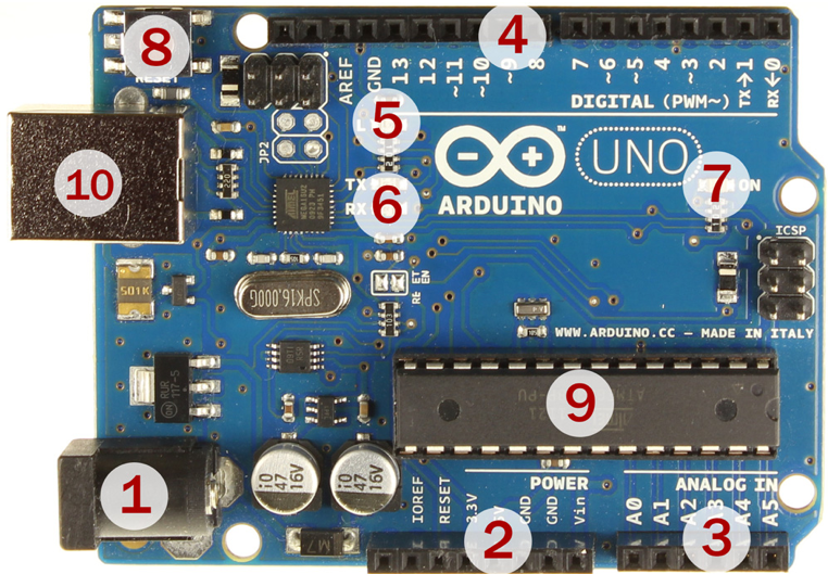
Parts of the Arduino UNO Continued
5. Onboard LED: This LED is connected to digital pin 13. It is lit whenever pin 13 is high.
6. Transmitting/Receiving Indicators: "TX" and "RX" LEDs indicate when serial communication is happening. Serial communication happens when the board is communicating with the computer. Example: When you upload a new program to the board.
7. Power Indicator: Power LED
8. Reset Button: This button resets the Arduino and your program restarts from the beginning.
9. Microcontroller: Type ATmega328 – the “brain” of the board
10. USB jack: connects to the computer for power as well as for communication
Circuit Basics
3
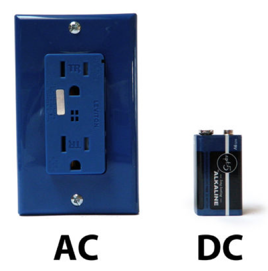
Current
There are two types of electrical signals, those being alternating current (AC), and direct current (DC).
Current is the motion of electrons along a path or conducting wire. It is the number of electrons passing a given point in a second.
The electrons flow from negative to positive, but the current is measured as going from positive to negative.


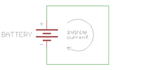
Short Circuits
There needs to be something wired between positive and ground that adds resistance to the flow of electricity and uses it up. If positive voltage is connected directly to ground and does not first pass through something that adds resistance, this will result in a short circuit.
Shorts are bad because they will result in your battery and/or circuit overheating, breaking, catching on fire, and/or exploding. It creates an “infinite loop”.
Note: Resistors and motors are good examples of objects that adds resistance.

Resistors
Resistors add resistance to the circuit and reduces the flow of electrical current. It is represented in a circuit diagram as a pointy squiggle with a value next to it.
The different markings on the resistor represent different values of resistance. These values are measured in ohms.
You read the values from left to right towards the (typically) gold band. The first two colors represent the resistor value, the third represents the multiplier, and the fourth (the gold band) represents the tolerance or precision of the component. You can tell the value of each color by looking at a resistor color value chart.
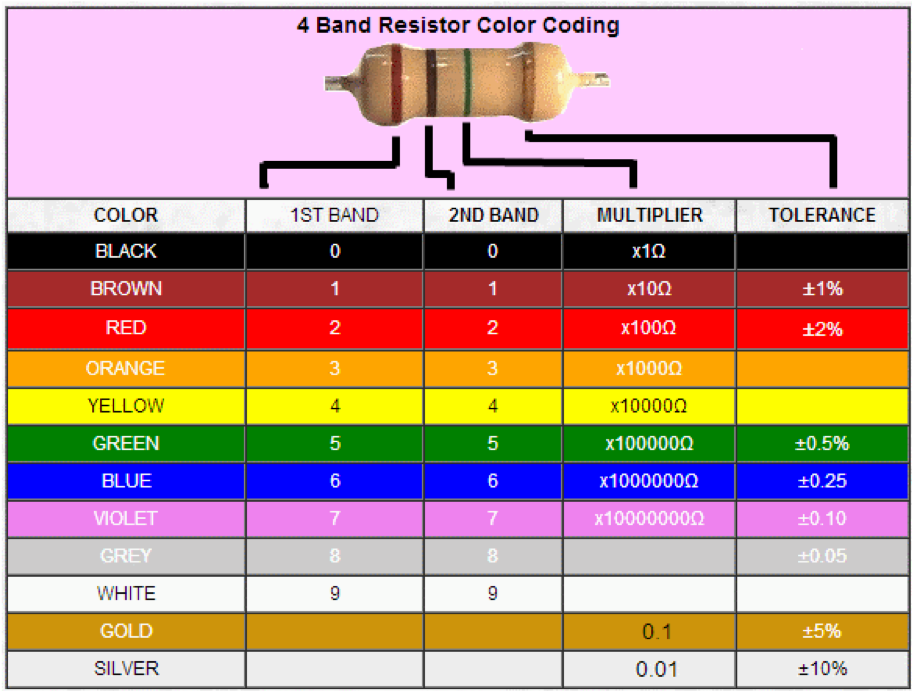
http://www.dannyg.com/examples/res2/resistor.htm - Resistor Calculator
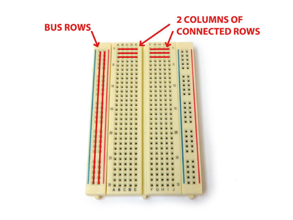
Breadboard
A breadboard is a solderless device for temporary prototype with electronics and test circuit designs. Most electronic components in electronic circuits can be interconnected by inserting their leads or terminals into the holes and then making connections through wires where appropriate.
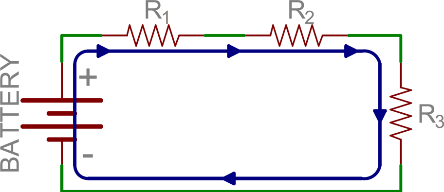
Series Circuits
Two components are in series if they share a common node and if the same current flows through them. There’s only one way for the current to flow in the circuit.

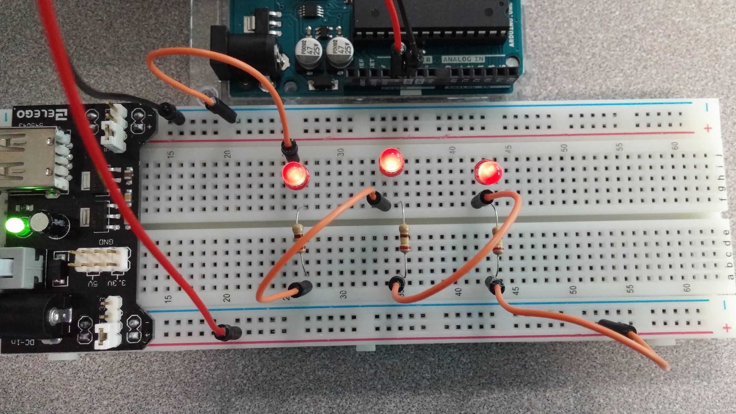
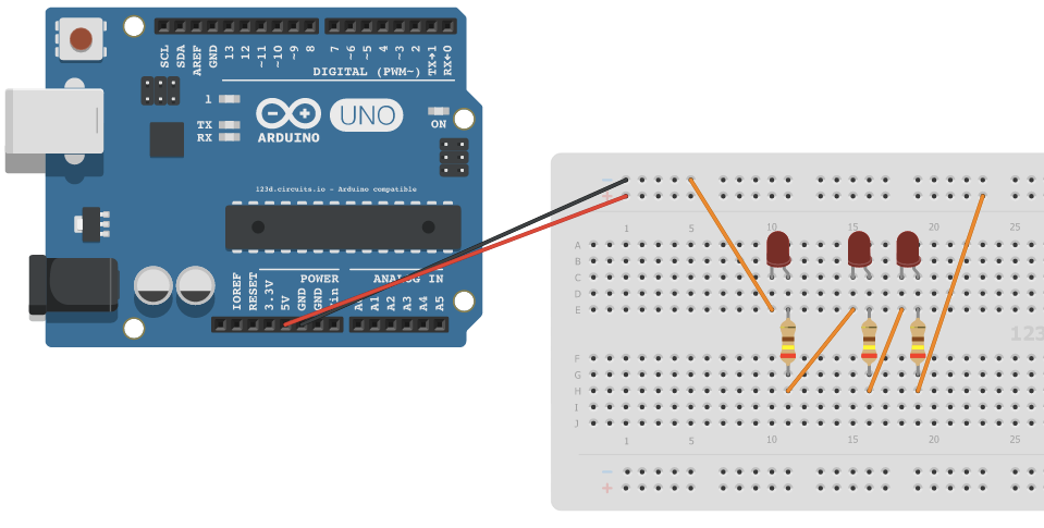
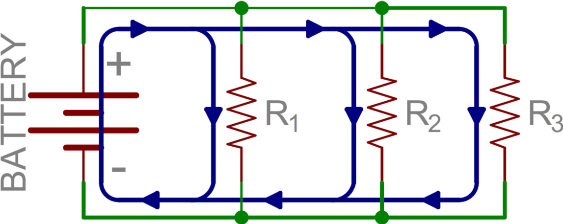
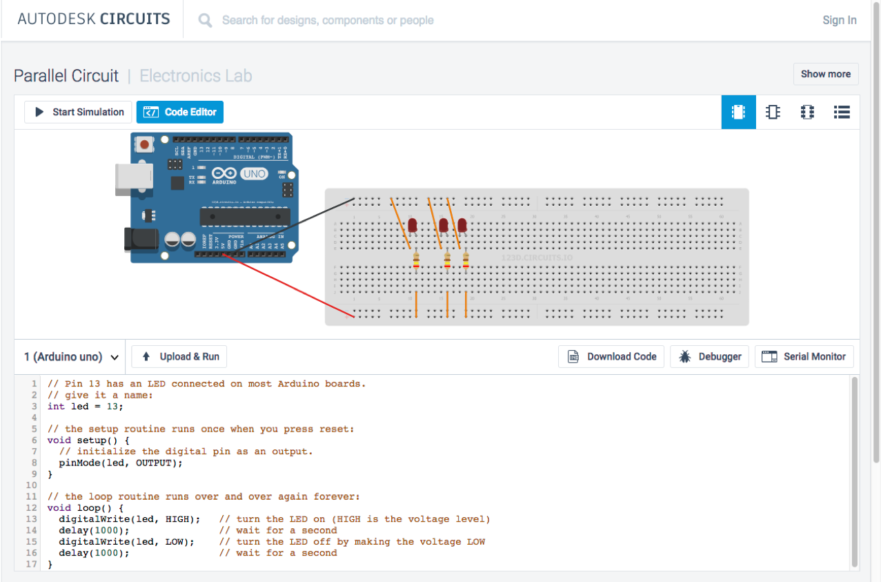
Parallel Circuits
If components share two common nodes, they are in parallel. In the examples on this page, there are three distinct paths that current can take before returning to the battery, and the associated resistors are said to be in parallel.
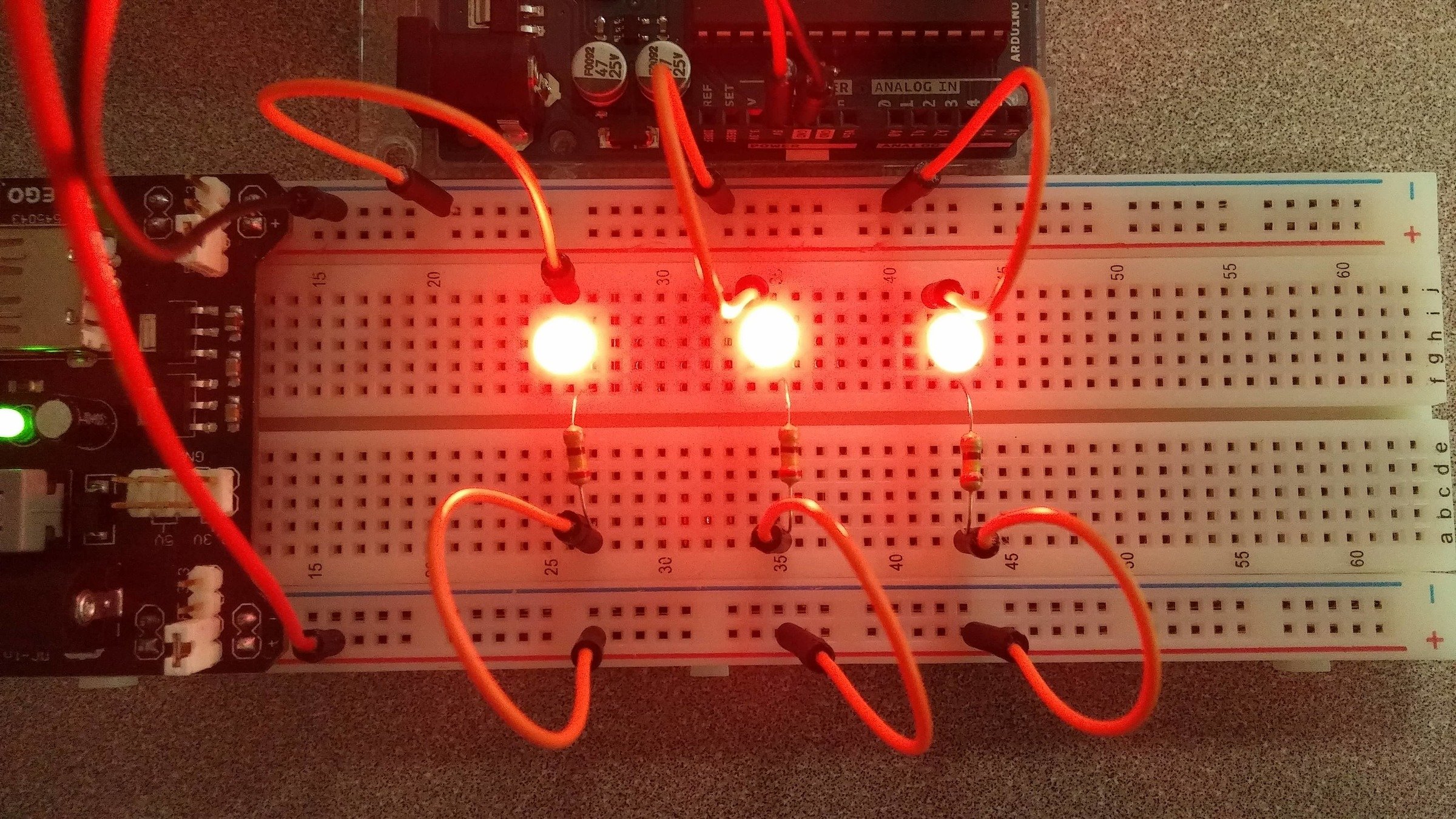
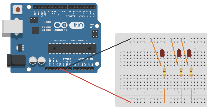
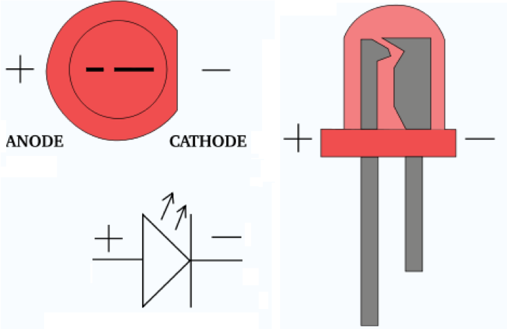
Light Emitting Diodes (LEDs)
There are typically two indicators to let you know what direction electricity will pass through and LED. The first indicator that the LED will have a longer positive lead (anode) and a shorter ground lead (cathode). The other indicator is a flat notch on the side of the LED to indicate the positive (anode) lead.
Like all diodes, LEDs create a voltage drop in the circuit, but typically do not add much resistance. In order to prevent the circuit from shorting, you need to add a resistor in series.
You may be tempted to wire LEDs in series, but keep in mind that each consecutive LED will result in a voltage drop until finally there is not enough power left to keep them lit. As such, it is ideal to light up multiple LEDs by wiring them in parallel. However, you need to make certain that all of the LEDs have the same power rating before you do this (different colors often are rated differently).


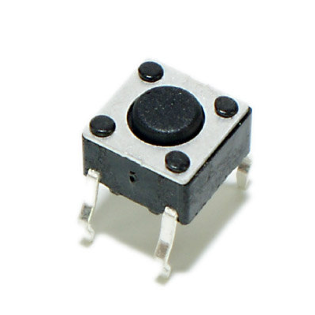
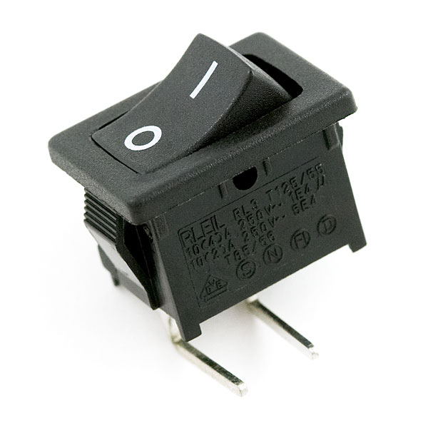
Switches/Buttons
A switch is basically a mechanical device that creates a break in a circuit. When you activate the switch, it opens or closes the circuit. This is dependent on the type of switch it is.

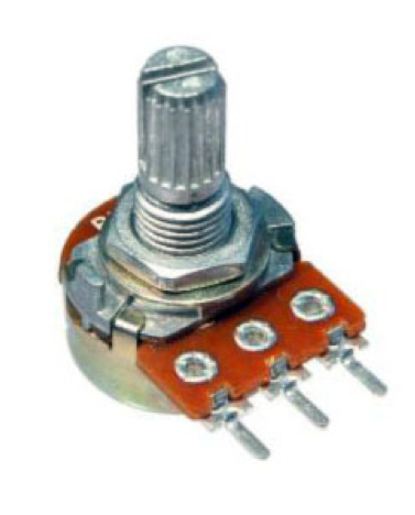
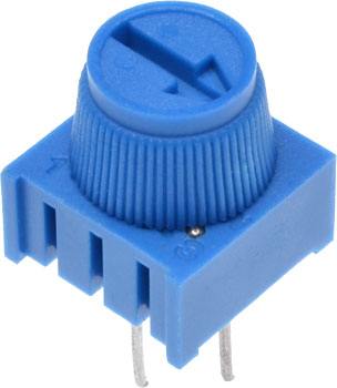
Potentiometers
Potentiometers are variable resistors. In plain English, they have some sort of knob or slider that you turn or push to change resistance in a circuit. If you have ever used a volume knob on a stereo or a sliding light dimmer, then you have used a potentiometer.
Potentiometers are measured in ohms like resistors, but rather than having color bands, they have their value rating written directly on them (i.e. "1M").
Analog vs. Digital
4
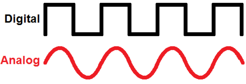
Digital vs. Analog
Digital is either ON or OFF / HIGH or LOW, logic 1 or logic 0, +5v or 0v
Analog is a continuous signal
Floating Input, Pullup/Pulldown Resistors
There is an issue with mechanical inputs (buttons, etc):
Pins configured as pinMode(pin, INPUT) with nothing connected to them, or with wires connected to them that are not connected to other circuits, will report seemingly random changes in pin state, picking up electrical noise from the environment
Often it is useful to steer an input pin to a known state if no input is present. This can be done by adding a pullup resistor (to +5V), or a pulldown resistor (resistor to ground) on the input. A 10K resistor is a good value for a pullup or pulldown resistor.
Generally, pulldown resistors are used.
Debouncing
“Bounciness” – When you press a button down, it may not make contact to both sides at the exact same moment –it may make contact on one side – then both – and then the other side – until it finally settles down. This making and breaking contact is called bouncing. It is not a manufacturing defect of the button – bouncing is implicit in most every physical switch.
It all happens in a matter of milliseconds – but your microcontroller is moving so fast that it will detect a transition between two states every time your button bounces.
Debouncing is checking if the value has settled before actually using the value.
Analog Output
Most microcontrollers have digital outputs - as we know digital is either 1 or 0 / 5v or 0v - analog is a range of values.
Arduino Uno has no true analog output (some Arduinos do).
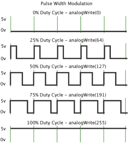
Pulse Width Modulation (PWM) is a technique used to create pseudo-analog signals.
PWM
Pulse Width Modulation, or PWM, is a technique for getting analog results with digital means. Digital control is used to create a square wave, a signal switched between on and off. This on-off pattern can simulate voltages in between full on (5 Volts) and off (0 Volts) by changing the portion of the time the signal spends on versus the time that the signal spends off.
PWM Continued
“A call to analogWrite() is on a scale of 0 - 255, such that analogWrite(255) requests a 100% duty cycle (always on), and analogWrite(127) is a 50% duty cycle (on half the time) for example.”
On most Arduino, the PWM pins are identified with
a "~" sign, like ~3, ~5, ~6, ~9, ~10 and ~11.
Coding
5
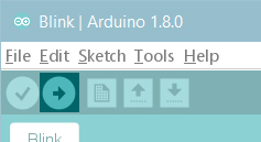
Software/IDE
“The Arduino development environment contains a text editor for writing code, a message area, a text console, a toolbar with buttons for common functions, and a series of menus. It connects to the Arduino hardware to upload programs and communicate with them. “
Available as software IDE, or a web editor.
http://arduino.cc/en/Main/Software - software
http://arduino.cc/en/Guide/Environment - full guide to IDE
Web Editor
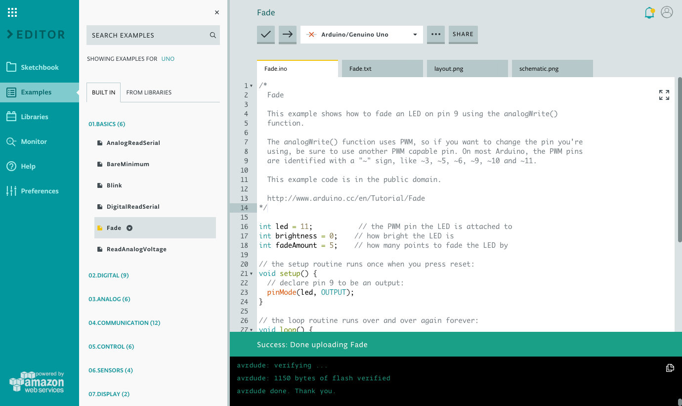
IDE
Language
Runs on C++ code
Rule of thumb – generally, the same code rules and structure apply as with JavaScript.
Control Structure
break
continue
do...while
else
for
goto
if...else
return
switch...case
while
Constants
Floating Point Constants
Integer Constants
HIGH | LOW
INPUT | OUTPUT | INPUT_PULLUP
LED_BUILTIN
true | false
Starting Code
Every Arduino Sketch needs the setup and loop code:
void setup() {
    /* put your setup code here, to run once:
    The setup() function is called when a sketch starts.
    Use it to initialize variables, pin modes, start
    using libraries, etc. The setup function will only
    run once, after each powerup or reset of the
    Arduino board. */
}

void loop() {
    /* Put your main code here, to run repeatedly:
    After creating a setup() function, which initializes
    and sets the initial values, the loop() function does
    precisely what its name suggests, and loops
    consecutively, allowing your program to change and
    respond. Use it to actively control the
    Arduino board. */
}
pinMode
Initialize a pin as an input or output pin with the line:
pinMode(pin, mode)
- pin: the number of the pin whose mode you wish to set (LED_BUILTIN, A0...A5, or 0...13)
- mode: INPUT, OUTPUT, or INPUT_PULLUP
void setup() {
    pinMode(LED_BUILTIN, OUTPUT);
}

void loop() {
    /* ... */
}digitalWrite
Turn the LED on by supplying 5 volts to the LED anode, using the line:
digitalWrite(pin, HIGH);
Turn it off by taking the pin back to 0 volts, using the line:
digitalWrite(pin, LOW);
void setup() {
    pinMode(LED_BUILTIN, OUTPUT);
}

void loop() {
    digitalWrite(LED_BUILTIN, HIGH);
    digitalWrite(LED_BUILTIN, LOW);
}
digitalWrite continued
int buttonPin = A0;
int ledPin1 = 8;
int ledPin2 = 9;
int ledPin3 = 10;
int ledState1 = HIGH;
int ledState2 = LOW;
int ledState3 = LOW;

void setup() {
    pinMode(buttonPin, INPUT);
    pinMode(ledPin1, OUTPUT);
    pinMode(ledPin2, OUTPUT);
    pinMode(ledPin3, OUTPUT);

    // set initial LED state
    digitalWrite(ledPin1, ledState1);
    digitalWrite(ledPin2, ledState2);
    digitalWrite(ledPin3, ledState3);
}

void loop() {
    /* ... */
}
You can use digitalWrite in the setup function to set the initial state of the pin.
delay
The delay(#) commands tell the board to do nothing for # milliseconds.
void setup() {
    pinMode(LED_BUILTIN, OUTPUT);
}

void loop() {
    digitalWrite(LED_BUILTIN, HIGH);
    delay(1000);
    digitalWrite(LED_BUILTIN, LOW);
    delay(1000);
}
Listening to the Board
We can confirm or debug our circuit by using the Serial Monitor.
Serial.begin(baud rate) - starts communications between the Arduino and your computer.
Baud Rate - data rate in bits per second (baud) for serial data transmission
Serial.println() - sends information to the serial port, which you can monitor through the Arduino IDE using Serial Monitor
Serial.begin
Begin serial communications, at 9600 bits of data per second, between your board and your computer with the command:
Serial.begin(9600);
void setup() {
    Serial.begin(9600);
}

void loop() {
    /* ... */
}
Serial.println
When you need to print this information to your serial monitor window, use the following line:
Serial.println(sensorValue)
void setup() {
    Serial.begin(9600);
    pinMode(2, INPUT);
}

void loop() {
    int sensorValue = digitalRead(2);
    Serial.println(sensorValue);
}
analogRead
Establish a variable to store the value, then set the value from the analog pin to it:
analogRead(pin);
void setup() {
    Serial.begin(9600);
    pinMode(A0, INPUT);
}

void loop() {
    int sensorValue = analogRead(A0);
}
digitalRead
Read that value that is on the specified digital pin:
digitalRead(pin)
void setup() {
    Serial.begin(9600);
    pinMode(2, INPUT);
}

void loop() {
    int sensorValue = digitalRead(2);
}
Getting Started
6
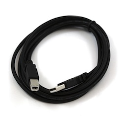
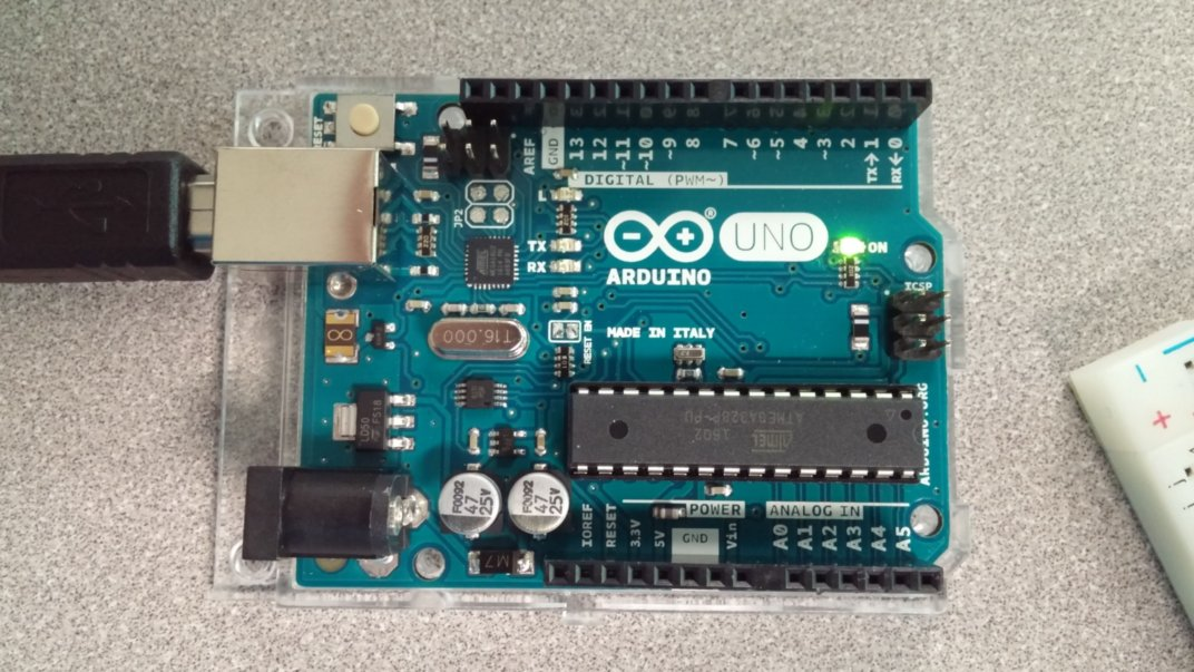
Connect with computer
Connect your Uno board with an A B USB cable; sometimes this cable is called a USB printer cable.
The USB connection with the PC is necessary to program the board and not just to power it up. The Uno automatically draw power from either the USB or an external power supply. Connect the board to your computer using the USB cable. The green power LED (labelled PWR) should go on.
https://www.arduino.cc/en/Guide/ArduinoUno
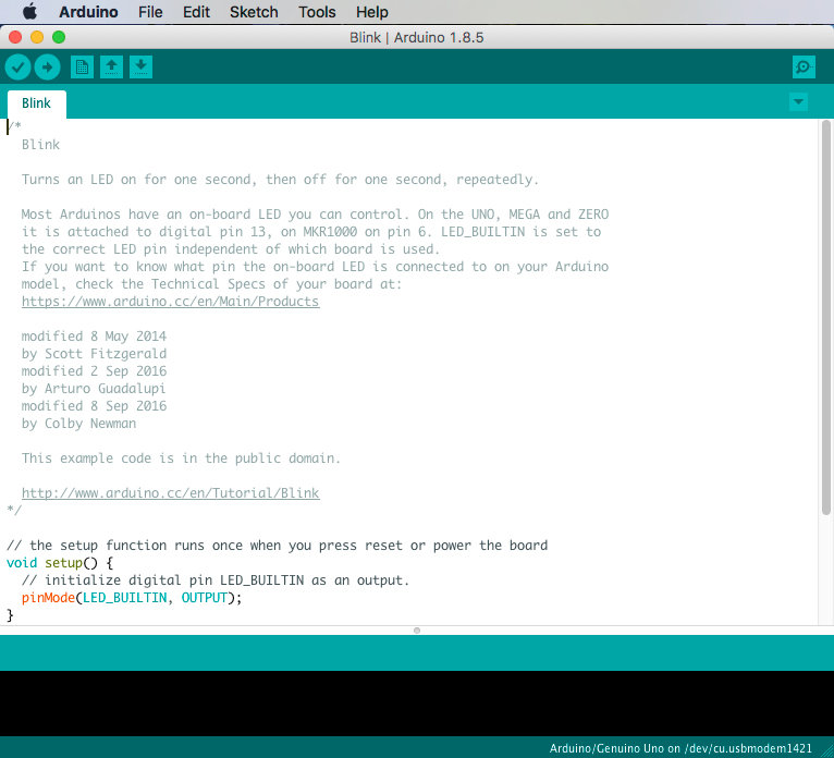
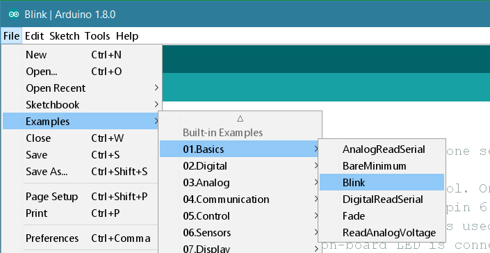
Open sketch (code)
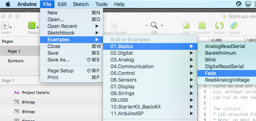
Open the sketch file
(Ex. the LED blink example sketch:
File > Examples >01.Basics > Blink.File > Examples >01.Basics > Blink )
https://www.arduino.cc/en/Guide/ArduinoUno
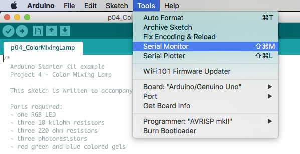
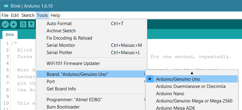
Select board type
Select the entry in the Tools > Board menu that corresponds to your Arduino or Genuino board.
https://www.arduino.cc/en/Guide/ArduinoUno
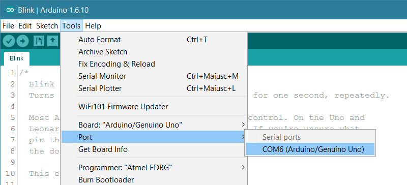
Select port
Select the serial device of the board from the Tools | Serial Port menu.
Note: on a Mac, the serial port may be /dev/tty.usbmodem1421
https://www.arduino.cc/en/Guide/ArduinoUno
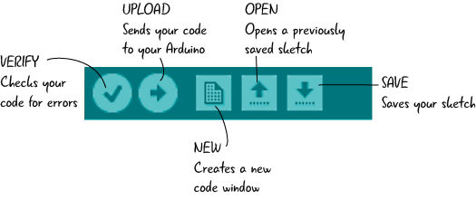
Upload program
Click the "Upload" button in the environment.
Wait a few seconds - you should see the RX and TX leds on the board flashing. If the upload is successful, the message "Done uploading." will appear in the status bar.
Optionally, before uploading, you should verify your code using the Verify button.
Program running
If you ran the 'Blink' code example, a few seconds after the upload finishes, you should see the pin 13 LED on the board start to blink (in orange). If it does, congratulations! You've gotten Arduino or Genuino up-and-running.
Examples
7
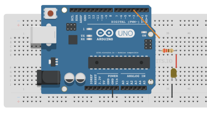
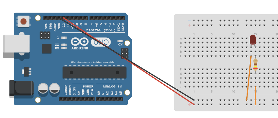
Analog Output - PWM
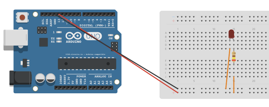
Fade Example
Example:
To have the brightness of an LED change over time.
This is an example of an analog output (LED), using one of the PWM (Pulse Width Modulation) pins.
- Intro
- Circuit
- Code
- Result
Analog Output - PWM
Fade Example
- Intro
- Circuit
- Code
- Result
Components:
- 1 LED
- 1 Resistor (220 Ohms)
Analog Output - PWM
Fade Example
- Intro
- Circuit
- Code
- Result
Analog Output - PWM
Fade Example
/*
  This example shows how to fade an LED on pin 3
  using the analogWrite() function.
*/

int led = 3;           // the PWM pin the LED is attached to
int brightness = 0;    // how bright the LED is
int fadeAmount = 5;    // how many points to fade the LED by

// the setup routine runs once when you press reset:
void setup() {
    // declare pin 3 to be an output:
    pinMode(led, OUTPUT);
}

// the loop routine runs over and over again forever:
void loop() {
    // set the brightness of pin 3:
    analogWrite(led, brightness);

    // change the brightness for next time through the loop:
    brightness = brightness + fadeAmount;

    // reverse the direction of the fading at the ends of the fade:
    if (brightness <= 0 || brightness >= 255) {
        fadeAmount = -fadeAmount;
    }
    // wait for 30 milliseconds to see the dimming effect
    delay(30);
}- Intro
- Circuit
- Code
- Result
Analog Output - PWM
Fade Example
The one LED connected to Port 9 (with PWM) starts off, fades on, and then fades off.
- Intro
- Circuit
- Code
- Result
- Intro
- Circuit
- Code
- Result
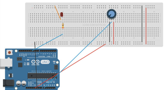
Analog Input
Potentiometer value logged to Monitor
Example:
To log the potentiometer value to the Serial Monitor.
This is an example of an analog input (potentiometer).
Analog Input
Potentiometer value logged to Monitor
- Intro
- Circuit
- Code
- Result
Components:
- 1 Potentiometer
Analog Input
Potentiometer value logged to Monitor
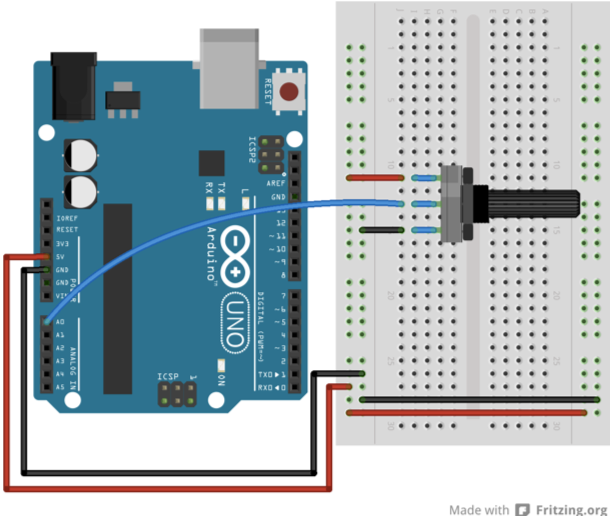
▰/*
  AnalogReadSerial

  Reads an analog input on pin 0, prints the result
  to the Serial Monitor.
  Graphical representation is available using
  Serial Plotter (Tools > Serial Plotter menu).
  Attach the center pin of a potentiometer to pin A0,
  and the outside pins to +5V and ground.
*/

int potPin = 0; // Analog Input Pin

// the setup routine runs once when you press reset:
void setup() {
  // initialize serial communication at 9600 bits per second:
  Serial.begin(9600);
}

// the loop routine runs over and over again forever:
void loop() {
  // read the input on analog pin 0:
  int sensorValue = analogRead(potPin);
  // print out the value you read:
  Serial.println(sensorValue);
  delay(500); // delay in between reads for stability
}- Intro
- Circuit
- Code
- Result
Analog Input
Potentiometer value logged to Monitor
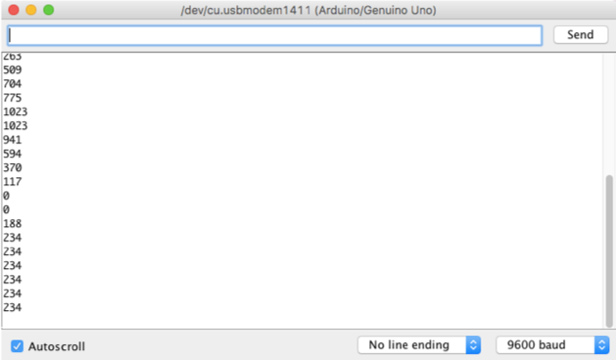
Turning the knob on the potentiometer changes the value printed out on the Serial Monitor. The lowest is 0, the highest is 1023.
- Intro
- Circuit
- Code
- Result
Digital Output
LED brightness changes
- Intro
- Circuit
- Code
- Result
Example:
To have the brightness of an LED change over time, without using the delay() function. This means that other code can run at the same time without being interrupted by the LED code.
This is an example of a digital output (LED).
Digital Output
LED brightness changes
- Intro
- Circuit
- Code
- Result
Components:
- 1 LED
- 1 Resistor (220 Ohms)
Digital Output
LED brightness changes
- Intro
- Circuit
- Code
- Result
const int ledPin =  13;      // the number of the LED pin

int ledState = LOW;          // ledState used to set the LED
long previousMillis = 0;     // will store last time LED was updated

long interval = 1000;        // interval at which to blink (milliseconds)

void setup() {
  pinMode(ledPin, OUTPUT);   // set the digital pin as output
}

void loop()
{
  unsigned long currentMillis = millis(); //Returns the number of
  // milliseconds since the Arduino board began
  // running the current program

  // check to see if it's time to blink the LED; that is, if the
  // difference between the current time and last time you blinked
  // the LED is bigger than the interval at which you want to
  // blink the LED.
  if(currentMillis - previousMillis > interval) {
    previousMillis = currentMillis; // save the last time you blinked the LED

    // if the LED is off turn it on and vice-versa:
    if (ledState == LOW)
      ledState = HIGH;
    else
      ledState = LOW;

    digitalWrite(ledPin, ledState); // set the LED with the ledState of the variable
  }
}
Digital Output
LED brightness changes
This turns the LED on and off every second. The light on the Arduino board also does the same.
- Intro
- Circuit
- Code
- Result
Analog Input and Digital Output
Potentiometer knob controls brightness of LED
- Intro
- Circuit
- Code
- Result
Example:
To have the brightness of an LED change over based on the value from the potentiometer.
It reads an analog input pin, maps the result to a range from 0 to 255 and uses the result to set the pulse width modulation (PWM) of an output pin. It also prints to the Serial Monitor.
This is an example that uses both an analog input (potentiometer) and an digital output (LED).
Analog Input and Digital Output
Potentiometer knob controls brightness of LED
- Intro
- Circuit
- Code
- Result
Components:
- 1 LED
- 1 Resistor (240 Ohms)
- 1 Potentiometer
Analog Input and Digital Output
Potentiometer knob controls brightness of LED
// These constants won't change.  They're used to give names to the pins used:
const int analogInPin = 0;  // Analog input pin that the potentiometer is attached to
const int PWMOutPin = 11;   // Analog output pin that the LED is attached to

int sensorValue = 0;        // value read from the pot
int outputValue = 0;        // value output to the PWM (analog out)

void setup() {
    Serial.begin(9600);     // initialize serial communications at 9600 bps
}

void loop() {
    sensorValue = analogRead(analogInPin); // read the analog in value

    // map it to the range of the analog out:
    outputValue = (255.00 *((float)sensorValue/1023.00));
        // note: decimals must be used in order to calculate a float (.00)
    // Instead of using the previous line, you can also use map():
    //outputValue = map(sensorValue, 0, 1023, 0, 255);

    analogWrite(PWMOutPin, outputValue); // change the analog out value

    // print the results to the serial monitor:
    Serial.print("sensor = " );
    Serial.print(sensorValue);
    Serial.print("\t output = ");
    Serial.println(outputValue);

    // wait 2 milliseconds before the next loop
    // for the analog-to-digital converter to settle
    // after the last reading:
    delay(2);
}- Intro
- Circuit
- Code
- Result
Analog Input and Digital Output
Potentiometer knob controls brightness of LED
Turning the potentiometer dial in one direction fades the LED, and turning it in the other direction makes it brighter.
- Intro
- Circuit
- Code
- Result
- Intro
- Circuit
- Code
- Result
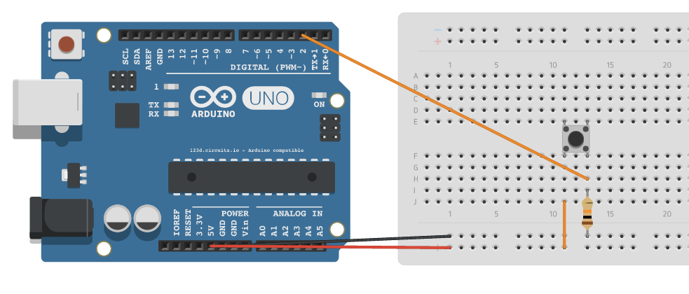
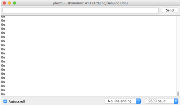
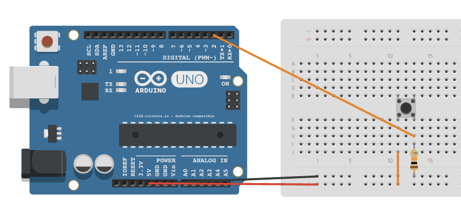
Digital Input
Button prints status in Monitor
Example:
To have the status of the button being pressed printed out to the Serial Monitor (Ex. "On" or "Off").
This is an example of a digital input (button).
Digital Input
Button prints status in Monitor
- Intro
- Circuit
- Code
- Result
Components:
- 1 Button
- 1 Resistor (10 kOhms)
- Intro
- Circuit
- Code
- Result
Digital Input
Button prints status in Monitor
// constants won’t change. They’re used here to set pin numbers:
const int buttonPin = 2;   // the number of the pushbutton pin
int buttonState = 0;       // variable for reading the pushbutton status

void setup() {
  // initialize serial communication at 9600 bits per second:
  Serial.begin(9600);
  pinMode(buttonPin, INPUT); // initialize the pushbutton pin as an input
}

void loop(){
  // read the state of the pushbutton value:
  buttonState = digitalRead(buttonPin);

  // check if the pushbutton is pressed.
  // if it is, the buttonState is HIGH:
  if (buttonState == 1) {
    Serial.println("On");
  } else {
    Serial.println("Off");
  }
}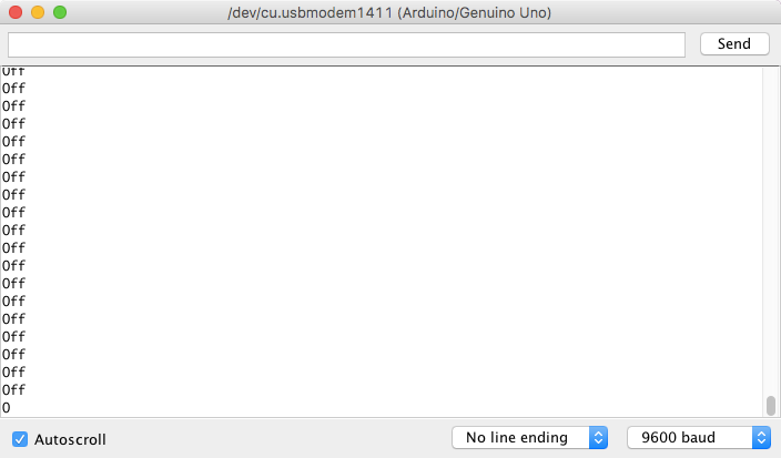
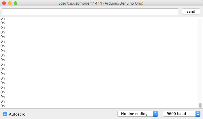
The Serial Monitor keeps printing out 'Off', and while the button is pressed it prints 'On'. No other changes are visible.
- Intro
- Circuit
- Code
- Result
Digital Input
Button prints status in Monitor
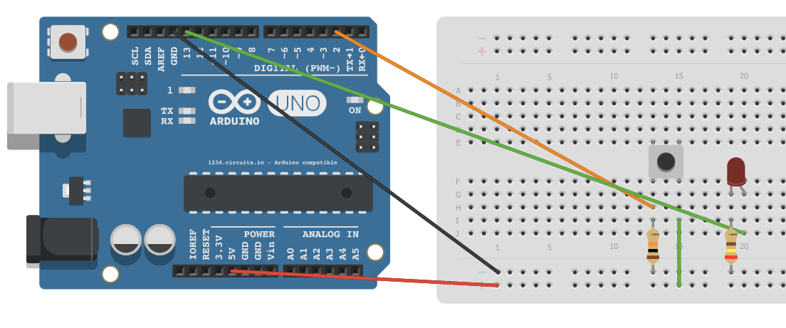
Digital Input and Output
Button controls status of LED
- Intro
- Circuit
- Code
- Result
Example:
Each time the input pin goes from LOW to HIGH (e.g. because of a push-button press), the output pin is toggled from LOW to HIGH or HIGH to LOW.
This is an example of both a digital input (button) and a digital output (LED).
- Intro
- Circuit
- Code
- Result
Components:
- 1 Button
- 1 LED
- 1 Resistor (240 Ohms)
- 1 Resistor (10 kOhms)
Digital Input and Output
Button controls status of LED
- Intro
- Circuit
- Code
- Result
Digital Input and Output
Button controls status of LED
// constants won’t change. They’re used here to set pin numbers:
const int buttonPin = 2; // the number of the pushbutton pin
const int ledPin = 13; // the number of the LED pin

// variables will change:
int buttonState = 0; // variable for reading the pushbutton status

void setup() {
  pinMode(ledPin, OUTPUT); // initialize the LED pin as an output
  pinMode(buttonPin, INPUT); // initialize the pushbutton pin as an input
}

void loop(){
  // read the state of the pushbutton value:
  buttonState = digitalRead(buttonPin);

  // check if the pushbutton is pressed.
  // if it is, the buttonState is HIGH:
  if (buttonState == 1) {
    digitalWrite(ledPin, HIGH); // turn LED on
  } else {
    digitalWrite(ledPin, LOW); // turn LED off
  }
}
Pressing the button usually turns the LED on when it is pressed, and off when the button is not pressed. It doesn't completely work though, since sometimes pressing the button keeps the LED light on even when the button isn't pressed anymore.
- Intro
- Circuit
- Code
- Result
Digital Input and Output
Button controls status of LED
Digital Input and Output (with debouncing)
Button controls status of LED
- Intro
- Circuit
- Code
- Result
Example:
Each time the input pin goes from LOW to HIGH (e.g. because of a push-button press), the output pin is toggled from LOW to HIGH or HIGH to LOW.
There's a minimum delay between toggles to debounce the circuit (i.e. to ignore noise).
This is an example of both a digital input (button) and a digital output (LED).
- Intro
- Circuit
- Code
- Result
Components:
- 1 Button
- 1 LED
- 1 Resistor (240 Ohms)
- 1 Resistor (10 kOhms)
Digital Input and Output (with debouncing)
Button controls status of LED
- Intro
- Circuit
- Code (1/2)
- Result
Digital Input and Output (with debouncing)
Button controls status of LED
// constants won't change. They're used here to set pin numbers:
const int buttonPin = 2;    // the number of the pushbutton pin
const int ledPin = 13;      // the number of the LED pin

// Variables will change:
int ledState = HIGH;         // the current state of the output pin
int buttonState;             // the current reading from the input pin
int lastButtonState = LOW;   // the previous reading from the input pin

// The following variables are unsigned longs
// because the time, measured in milliseconds, will quickly become
// a bigger number than can be stored in an int.
// The last time the output pin was toggled:
unsigned long lastDebounceTime = 0;
// The debounce time; increase if output flickers:
unsigned long debounceDelay = 50;

void setup() {
  pinMode(buttonPin, INPUT);
  pinMode(ledPin, OUTPUT);
  digitalWrite(ledPin, ledState); // set initial LED state
}Digital Input and Output (with debouncing)
Button controls status of LED
void loop() {
  // read the state of the switch into a local variable:
  int reading = digitalRead(buttonPin);

  // If the switch changed, due to noise or pressing:
  if (reading != lastButtonState) {
    lastDebounceTime = millis(); // reset the debouncing timer
  }

  // check to see if you just pressed the button, and you've waited
  // long enough since the last press to ignore any noise:
  if ((millis() - lastDebounceTime) > debounceDelay) {
    // whatever the reading is at, it's been there for longer than
    // the debounce delay, so take it as the actual current state:

    // if the button state has changed:
    if (reading != buttonState) {
      buttonState = reading;

      // only toggle the LED if the new button state is HIGH
      if (buttonState == HIGH) {
        ledState = !ledState;
      }
    }
  }

  digitalWrite(ledPin, ledState); // set the LED

  // Save the reading. Next time through the loop,
  // it'll be the lastButtonState:
  lastButtonState = reading;
}
- Intro
- Circuit
- Code (2/2)
- Result
The LED starts on, and as soon as the button is pressed, the LED turns off. After that, as soon as the button is pressed again, the LED turns on. Holding the button makes no difference since the LED state changes as soon as the button is pushed down.
- Intro
- Circuit
- Code
- Result
Digital Input and Output (with debouncing)
Button controls status of LED
Creating custom Arduino setups
8
Additional Components
Components are generally well-documented. You can find circuit diagrams and code online.
Check out:
- Arduino Tutorials - https://www.arduino.cc/en/Tutorial/HomePage
- Adafruit Examples - https://learn.adafruit.com/
- SparkFun - https://learn.sparkfun.com/
- Fritzing - http://fritzing.org/projects/
- Google!
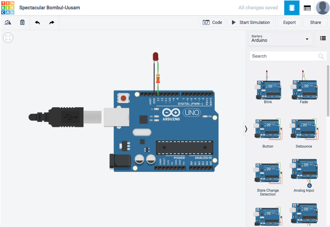
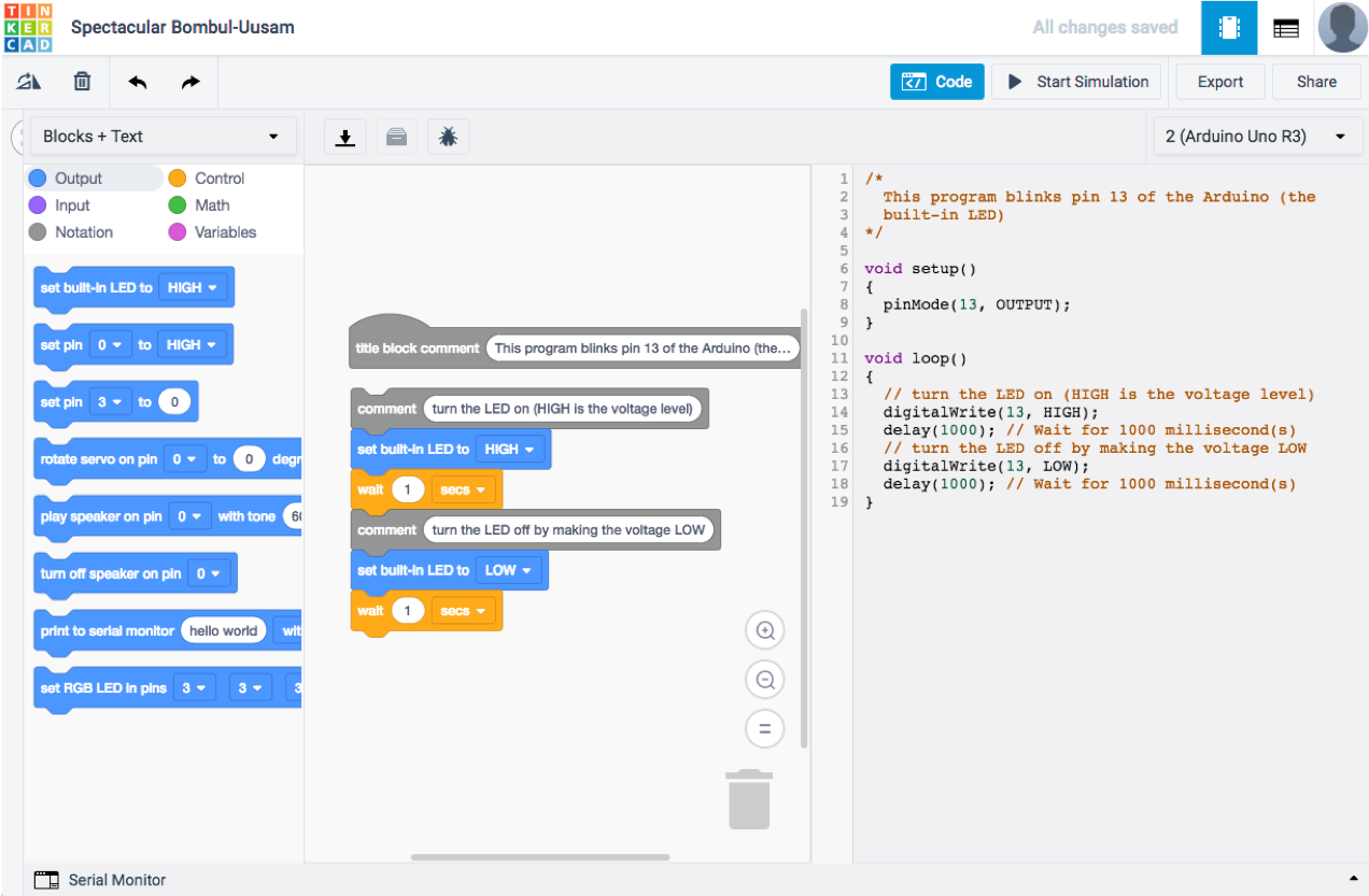
Designing and Testing
Check out Tinkercad to design your circuits, and code and simulate the results
Text
Text
Text
Additional Features
9
Additional Libraries
To support additional Arduino boards, sensors, or components, you may need to include and install additional libraries.
Inserting standard library:
-
Sketch - > Include Library
Contributed Libraries
-
recommended vs other
-
use cpp and h files
More Resources
Connect Arduino with cell phone:
- Blynk: http://www.blynk.cc/
- Adafruit IO: https://io.adafruit.com/
Connect Node.js and Arduino through Serial:
Further questions?
Contact me at:
alison@alisonkhall.com
Introduction to ARDUINO
By Alison K. Hall