Midterm Big Home#1
04 - 63050025 - นายปฏิภาณ ยะคะเรศ
19 - 63050360 - นายอนพัทย์ จีรพัฒน์ดิษกุล
GPIO
(General Purpose Input Output)
# PRESENTING CODE
cyhal_gpio_init(pin,direction,drive_mode,init_val)
ใช้ในการเริ่มต้นและกำหนดค่าของขา GPIO
Parameters
[in]pin: ขา GPIO ที่จะทำการกำหนดค่าและเตรียมตัวทำงาน
[in]direction: ทิศทางการทำงานของขา GPIO
[in]drive_mode: โหมดการขับเคลื่อนของขา GPIO
[in]init_val: ค่าเริ่มต้นที่จะกำหนดให้กับขา GPIO เมื่อทำการเริ่มต้นใช้งาน
cyhal_gpio_write ( pin, value)
ใช้ในการกำหนดค่าoutput value สำหรับขา GPIO
Parameters
[in] pin: object GPIO ที่ต้องการกำหนดค่า
[in]value: ค่าที่ต้องการตั้ง (high = true, low = false)
    cy_rslt_t rslt;
    bool      write_val = true;

    // Initialize pin P0_0 GPIO as an output with strong drive mode and initial value = false (low)
    rslt = cyhal_gpio_init(P0_0, CYHAL_GPIO_DIR_OUTPUT, CYHAL_GPIO_DRIVE_STRONG, false);

    // Write the value to the output pin
    cyhal_gpio_write(P0_0, write_val);
โค้ดตัวอย่างนี้กำหนดขา GPIO เป็น output และตั้งให้เป็นแบบ strong drive mode, ซึ่งจะมีค่าเริ่มต้นเป็น low(false) จากนั้นก็กำหนดให้เป็น high(true)
# PRESENTING CODE
cyhal_gpio_read(pin)
ใช้ในการอ่านค่าเข้าของขา GPIO
Parameters
[in] pin: object GPIO ที่ต้องการอ่านค่า
Returns:
ค่าของขา GPIO (true = high, false = low)
cyhal_gpio_toggle(cyhal_gpio_t pin)
ใช้ในการสลับ (toggle) ค่าเอาต์พุตของขา GPIO
Parameters
[in] pin: object GPIO ที่ต้องการทำการสลับค่าเอาต์พุต
#include "cyhal_gpio.h"

int main(void)
{
    // เลือกขา GPIO ที่ต้องการใช้งาน
    cyhal_gpio_t gpioPin = CYHAL_GPIO_P15;

    // กำหนดขา GPIO เป็นเอาต์พุต (output)
    cyhal_gpio_init(gpioPin, CYHAL_GPIO_DIR_OUTPUT, CYHAL_GPIO_DRIVE_STRONG, CYHAL_GPIO_DRIVE_HIGH);

    while (1)
    {
        // ทำการสลับค่าเอาต์พุตของขา GPIO
        cyhal_gpio_toggle(gpioPin);

        // อ่านค่าเข้าของขา GPIO
        bool readValue = cyhal_gpio_read(gpioPin);

        // ตรวจสอบค่าที่ได้จากการอ่านและทำการประมวลผลต่อไป
        if (readValue)
        {
            printf("GPIO Pin is HIGH\n");
        }
        else
        {
            printf("GPIO Pin is LOW\n");
        }
    }

    return 0;
}
ตัวอย่างการใช้งานเบื้องต้นของขา GPIO สลับสถานะ และอ่านค่า
PWM
(Pulse Width Modulator)
# PRESENTING CODE
cyhal_pwm_init( obj,pin,clk)
กำหนดค่าเริ่มต้นและควบคุม PWM และยังสามารถกำหนดค่า pin
Parameters
[out] obj ตัวชี้ไป object PWM
[in] pin พิน PWM ที่ต้องการที่จะเริ่มต้น ต้องระบุพินนี้ ไม่สามารถเป็น NC
[in] clk นาฬิกาที่กำหนดไว้ล่วงหน้า (optional) หากเป็นค่าว่างเปล่าจะถูกจัดสรรนาฬิกาใหม่
cyhal_pwm_start and cyhal_pwm_stop functions can be used after PWM initialization to start and stop the PWM output.
    cyhal_pwm_t pwm_obj;

    // Initialize PWM on the supplied pin and assign a new clock
    rslt = cyhal_pwm_init(&pwm_obj, P0_0, NULL);
    CY_ASSERT(CY_RSLT_SUCCESS == rslt);

    // Set a duty cycle of 50% and frequency of 1Hz
    rslt = cyhal_pwm_set_duty_cycle(&pwm_obj, 50, 1);

    while (loop)
    {
        // Stop the PWM output
        rslt = cyhal_pwm_stop(&pwm_obj);

        // Delay for observing the output
        cyhal_system_delay_ms(5000);

        // (Re-)start the PWM output
        rslt = cyhal_pwm_start(&pwm_obj);

        // Delay for observing the output
        cyhal_system_delay_ms(5000);
    }
ตัวอย่างการกำหนดสัญญาณ PWM ให้กับขาที่ต้องการใช้งาน พร้อมทั้งกำหนดกำหนด duty cycle และความถี่ จากนั้นก็ทำการเริ่มและหยุดภายในลูป
cyhal_pwm_set_duty_cycle(obj,duty_cycle,frequencyhal_hz)
cy_rslt_t cyhal_pwm_set_duty_cycle (
cyhal_pwm_t * obj,
float duty_cycle,
uint32_t frequencyhal_hz)
เพื่อตั้ง Duty cycle และความถี่
Parameters
[in] obj object ของ PWM
[in] duty_cycle ปริมาณของเวลาเมื่อ Output เป็น HIGH โดยคิดเป็น %
[in] frequencyhal_hz ความถี่ของสัญญาญ PWM มีหน่วยเป็น Hz
# PRESENTING CODE
cyhal_pwm_stop(obj)
cy_rslt_t cyhal_pwm_stop ( cyhal_pwm_t * obj )
หยุดการสร้างและส่งออกของสัญญาณ PWM
Parameters
[in] obj object ของ PWM
cyhal_pwm_start and cyhal_pwm_stop functions can be used after PWM initialization to start and stop the PWM output.
    cyhal_pwm_t pwm_obj;

    // Initialize PWM on the supplied pin and assign a new clock
    rslt = cyhal_pwm_init(&pwm_obj, P0_0, NULL);
    CY_ASSERT(CY_RSLT_SUCCESS == rslt);

    // Set a duty cycle of 50% and frequency of 1Hz
    rslt = cyhal_pwm_set_duty_cycle(&pwm_obj, 50, 1);

    while (loop)
    {
        // Stop the PWM output
        rslt = cyhal_pwm_stop(&pwm_obj);

        // Delay for observing the output
        cyhal_system_delay_ms(5000);

        // (Re-)start the PWM output
        rslt = cyhal_pwm_start(&pwm_obj);

        // Delay for observing the output
        cyhal_system_delay_ms(5000);
}cyhal_pwm_start()
cy_rslt_t cyhal_pwm_start ( cyhal_pwm_t *obj )
เริ่มต้นการสร้างสัญญาณ PWM และส่งออกไป
Parameters
[in] obj The PWM object
Returns
สถานะของคำขอเริ่มต้นฟังก์ชั่น
ADC
(Analog to Digital Converter)
# PRESENTING CODE
cyhal_adc_init(obj, pin,clk)
cy_rslt_t cyhal_adc_init ( cyhal_adc_t *obj,cyhal_gpio_t pin,const cyhal_clock_t * clk)
เพื่อกำหนดขา ADC สำหรับใช้รับสัญญาณ Analog ภายนอก
Parameters
[out] obj Pointer ชี้ไปที่ ADC object. โดยที่จะต้องมีหน่วยความจำให้ object นี้ แต่ฟังก์ชั้่น init จะเป็นผู้กำหนดเนื้อหา
[in] pin ใช้ขาเดียวกันกับขาที่บล็อคสัญญาณ ADC เพื่อเริ่มต้นการทำงาน
(หมายเหตุ : ขานี้มีไว้เพียงเพื่อระบุว่าขาไหนเป็นขาที่บล็อคสัญญาณ ADC, ถ้าในกรณีที่มีหลายช่องสัญญาณ ในขณะที่มีขา ADC เพียงแค่ขาเดียว, จะมีเพียงช่องสัญญาณเดียวที่ผ่านไปได้ ไม่ว่าจะเป็นช่องไหนก็ตาม, หลังจากการเรียกใช้ฟังก์ชั่นนี้ครั้งหนึ่งแล้ว เรียกใช้ cyhal_adc_channel_init_diff สำหรับขาที่ต้องการวัดค่า)
[in] clk สัญญาณนาฬิกาใช้ร่วมกันได้ แต่ถ้าไม่ได้กำหนดจะทำการสร้างใหม่
Returns
ถ้าไม่สำเร็จ, error code จะถูก return ไปแทน, ปัญหาอาจเกิดได้ทั้งจาก HAL หรือ driver ที่มีระดับต่ำกว่า
#include "cy_pdl.h"
#include "cyhal.h"
#include "cybsp.h"
#include "cy_retarget_io.h"


int main(void)
{
    cy_rslt_t result;
    cyhal_adc_t adc_obj;
    cyhal_adc_channel_t adc_chan_0_obj;

    /* Initialize the device and board peripherals /
    result = cybsp_init() ;
    if (result != CY_RSLT_SUCCESS)
    {
        CY_ASSERT(0);
    }

    __enable_irq();

    / Initialize retarget-io to use the debug UART port /
    result = cy_retarget_io_init(CYBSP_DEBUG_UART_TX, CYBSP_DEBUG_UART_RX, CY_RETARGET_IO_BAUDRATE);
    CY_ASSERT(result == CY_RSLT_SUCCESS);

    / ADC conversion result. /
    int adc_out;

    / Initialize ADC. The ADC block which can connect to pin 10[6] is selected /
    result = cyhal_adc_init(&adc_obj, P10_6, NULL);

    // ADC configuration structure
    const cyhal_adc_config_t ADCconfig ={
        .continuous_scanning = false,
        .resolution = 12,
        .average_count = 1,
        .average_mode_flags = 0,
        .ext_vref_mv = 0,
        .vneg = CYHAL_ADC_VNEG_VREF,
        .vref = CYHAL_ADC_REF_VDDA,
        .ext_vref = NC,
        .is_bypassed = false,
        .bypass_pin = NC
    };

    // Configure to use VDD as Vref
    result = cyhal_adc_configure(&adc_obj, &ADCconfig);

    / Initialize ADC channel, allocate channel number 0 to pin 10[6] as this is the first channel initialized /
    const cyhal_adc_channel_config_t channel_config = { .enable_averaging = false, .min_acquisition_ns = 220, .enabled = true };
    result = cyhal_adc_channel_init_diff(&adc_chan_0_obj, &adc_obj, P10_6, CYHAL_ADC_VNEG, &channel_config);

    for (;;)
    {
        / Read the ADC conversion result for corresponding ADC channel. Repeat as necessary. */
        adc_out = cyhal_adc_read_uv(&adc_chan_0_obj);
        printf("ADC = %d\r\n", adc_out);
        cyhal_system_delay_ms(100);
    }
}
# PRESENTING CODE
cyhal_adc_configure(obj,config)
cy_rslt_t cyhal_adc_configure ( cyhal_adc_t * obj,
const cyhal_adc_config_t * config )
อัพเดตการตั้งค่าของ ADC
หมายเหตุ : ถ้าอยู่ในกระบวนการแสกน, อาจจะเป็นการขัดจังหวะได้
Parameters
[in] obj object ของ ADC
[in] config ค่าต่างๆที่ต้องการตั้งค่า
Returns
ถ้าล้มเหลว, error code จะถูก return ไปแทน, ปัญหาอาจเกิดได้ทั้งจาก HAL หรือ driver ที่มีระดับต่ำกว่า
#include "cy_pdl.h"
#include "cyhal.h"
#include "cybsp.h"
#include "cy_retarget_io.h"


int main(void)
{
    cy_rslt_t result;
    cyhal_adc_t adc_obj;
    cyhal_adc_channel_t adc_chan_0_obj;

    /* Initialize the device and board peripherals /
    result = cybsp_init() ;
    if (result != CY_RSLT_SUCCESS)
    {
        CY_ASSERT(0);
    }

    __enable_irq();

    / Initialize retarget-io to use the debug UART port /
    result = cy_retarget_io_init(CYBSP_DEBUG_UART_TX, CYBSP_DEBUG_UART_RX, CY_RETARGET_IO_BAUDRATE);
    CY_ASSERT(result == CY_RSLT_SUCCESS);

    / ADC conversion result. /
    int adc_out;

    / Initialize ADC. The ADC block which can connect to pin 10[6] is selected /
    result = cyhal_adc_init(&adc_obj, P10_6, NULL);

    // ADC configuration structure
    const cyhal_adc_config_t ADCconfig ={
        .continuous_scanning = false,
        .resolution = 12,
        .average_count = 1,
        .average_mode_flags = 0,
        .ext_vref_mv = 0,
        .vneg = CYHAL_ADC_VNEG_VREF,
        .vref = CYHAL_ADC_REF_VDDA,
        .ext_vref = NC,
        .is_bypassed = false,
        .bypass_pin = NC
    };
    result = cyhal_adc_configure(&adc_obj, &ADCconfig);

    / Initialize ADC channel, allocate channel number 0 to pin 10[6] as this is the first channel initialized /
    const cyhal_adc_channel_config_t channel_config = { .enable_averaging = false, .min_acquisition_ns = 220, .enabled = true };
    result = cyhal_adc_channel_init_diff(&adc_chan_0_obj, &adc_obj, P10_6, CYHAL_ADC_VNEG, &channel_config);

    for (;;)
    {
        / Read the ADC conversion result for corresponding ADC channel. Repeat as necessary. */
        adc_out = cyhal_adc_read_uv(&adc_chan_0_obj);
        printf("ADC = %d\r\n", adc_out);
        cyhal_system_delay_ms(100);
    }
}cyhal_adc_read_uv(obj)
int32_t cyhal_adc_read_uv(const cyhal_adc_channel_t * obj)
ใช้ในการอ่านค่าจากขา ADC และแสดงผลในหน่วยไมโครโวลต์ (microvolts)
Parameters
[in] obj: obj ADC ที่ต้องการอ่านค่า
Modify Code LAB107 Read ADC
# PRESENTING CODE
#include "cy_pdl.h"
#include "cyhal.h"
#include "cybsp.h"
#include "cy_retarget_io.h"
#define LED1_PIN CYBSP_LED_RGB_RED
#define LED2_PIN CYBSP_LED_RGB_GREEN
#define LED3_PIN CYBSP_LED_RGB_BLUE
int main(void)
{
cy_rslt_t result;
cyhal_adc_t adc_obj;
cyhal_adc_channel_t adc_chan_0_obj;
/* Initialize the device and board peripherals */
result = cybsp_init();
if (result != CY_RSLT_SUCCESS)
{
CY_ASSERT(0);
}
__enable_irq();
/* Initialize retarget-io to use the debug UART port */
result = cy_retarget_io_init(CYBSP_DEBUG_UART_TX, CYBSP_DEBUG_UART_RX, CY_RETARGET_IO_BAUDRATE);
CY_ASSERT(result == CY_RSLT_SUCCESS);
/* Initialize LED pins */
cyhal_gpio_init(LED1_PIN, CYHAL_GPIO_DIR_OUTPUT, CYHAL_GPIO_DRIVE_STRONG, CYBSP_LED_STATE_OFF);
cyhal_gpio_init(LED2_PIN, CYHAL_GPIO_DIR_OUTPUT, CYHAL_GPIO_DRIVE_STRONG, CYBSP_LED_STATE_OFF);
cyhal_gpio_init(LED3_PIN, CYHAL_GPIO_DIR_OUTPUT, CYHAL_GPIO_DRIVE_STRONG, CYBSP_LED_STATE_OFF);
/* ADC conversion result. */
int adc_out;
int adc_out1;
/* Initialize ADC. The ADC block which can connect to pin 10[6] is selected */
result = cyhal_adc_init(&adc_obj, P10_6, NULL);
// ADC configuration structure
const cyhal_adc_config_t ADCconfig ={
.continuous_scanning = false,
.resolution = 12,
.average_count = 1,
.average_mode_flags = 0,
.ext_vref_mv = 0,
.vneg = CYHAL_ADC_VNEG_VREF,
.vref = CYHAL_ADC_REF_VDDA,
.ext_vref = NC,
.is_bypassed = false,
.bypass_pin = NC
};
// Configure to use VDD as Vref
result = cyhal_adc_configure(&adc_obj, &ADCconfig);
/* Initialize ADC channel, allocate channel number 0 to pin 10[6] as this is the first channel initialized */
const cyhal_adc_channel_config_t channel_config = { .enable_averaging = false, .min_acquisition_ns = 220, .enabled = true };
result = cyhal_adc_channel_init_diff(&adc_chan_0_obj, &adc_obj, P10_6, CYHAL_ADC_VNEG, &channel_config);
for (;;)
{
/* Read the ADC conversion result for corresponding ADC channel. Repeat as necessary. */
adc_out = cyhal_adc_read_uv(&adc_chan_0_obj);
adc_out1 = (adc_out*30)/3304866;
printf("ADC = %d\r\n", adc_out);
if (adc_out1 >= 1 && adc_out1 <= 10)
{
cyhal_gpio_write(LED1_PIN, CYBSP_LED_STATE_ON);
cyhal_gpio_write(LED2_PIN, CYBSP_LED_STATE_OFF);
cyhal_gpio_write(LED3_PIN, CYBSP_LED_STATE_OFF);
}
else if (adc_out1 >= 11 && adc_out1 <= 20)
{
cyhal_gpio_write(LED1_PIN, CYBSP_LED_STATE_OFF);
cyhal_gpio_write(LED2_PIN, CYBSP_LED_STATE_ON);
cyhal_gpio_write(LED3_PIN, CYBSP_LED_STATE_OFF);
}
else if (adc_out1 >= 21 && adc_out1 <= 30)
{
cyhal_gpio_write(LED1_PIN, CYBSP_LED_STATE_OFF);
cyhal_gpio_write(LED2_PIN, CYBSP_LED_STATE_OFF);
cyhal_gpio_write(LED3_PIN, CYBSP_LED_STATE_ON);
}
else
{
cyhal_gpio_write(LED1_PIN, CYBSP_LED_STATE_OFF);
cyhal_gpio_write(LED2_PIN, CYBSP_LED_STATE_OFF);
cyhal_gpio_write(LED3_PIN, CYBSP_LED_STATE_OFF);
}
cyhal_system_delay_ms(100);
}
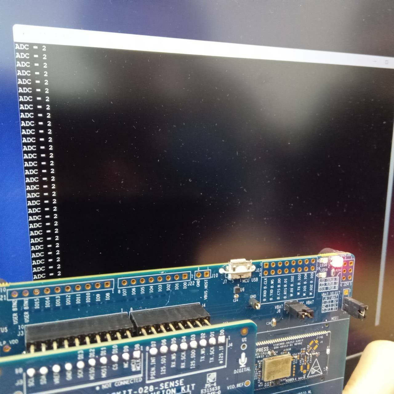
}โค้ดนี้ใช้ PSoC 6 (Platform System on Chip) เพื่อวัดและควบคุมไฟ LED จากสัญญาณแรงดันแอนะล็อกที่มีที่ขา P10_6 โดยใช้ ADC (Analog-to-Digital Converter) บนชิป PSoC 6 นี้
-
การอ่านแรงดันแอนะล็อก (ADC Reading Output): โค้ดนี้จะอ่านค่าแรงดันแอนะล็อกที่ป้อนเข้าที่ขา P10_6 และแปลงเป็นค่าดิจิตอลที่สามารถนำไปใช้ได้ โค้ดจะแสดงค่านี้ในรูปแบบ raw ที่ถูกอ่านจาก ADC ทางคอนโซลของระบบหรืออินเทอร์เฟซใดๆที่ใช้ในการดีบักข้อมูล
-
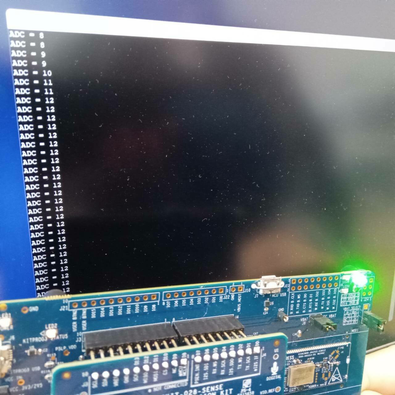
ควบคุมไฟ LED (LED Control): จากนั้นโค้ดจะทำการคำนวณ adc_out1 ซึ่งเป็นรูปแบบที่ scaled ของ adc_out โค้ดจะแมปค่าที่ได้จาก ADC ไปยังช่วงค่า 0 ถึง 30 จากนั้นจะควบคุมไฟ LED ตามเงื่อนไขต่อไปนี้:
- ถ้า adc_out1 อยู่ในช่วง 1-10, จะเปิด LED1 และปิด LED2 และ LED3
- ถ้า adc_out1 อยู่ในช่วง 11-20, จะเปิด LED2 และปิด LED1 และ LED3
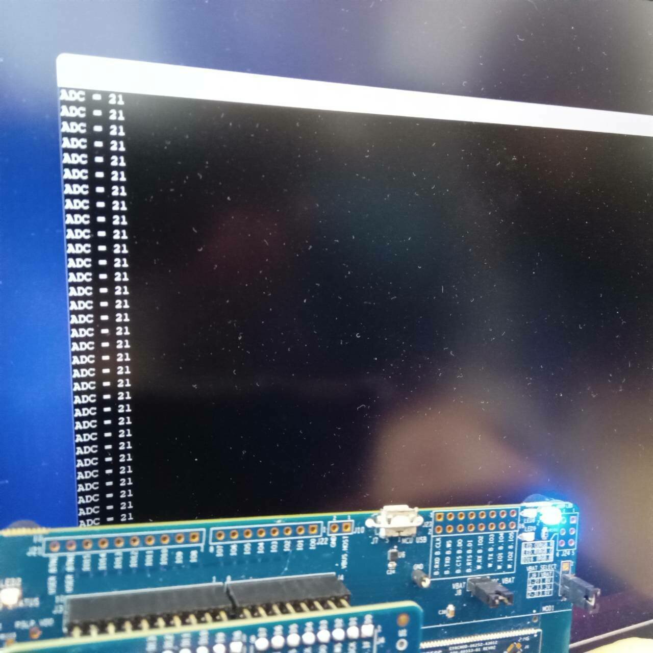
- ถ้า adc_out1 อยู่ในช่วง 21-30, จะเปิด LED3 และปิด LED1 และ LED2
- ถ้า adc_out1 ไม่อยู่ในช่วงเหล่านี้, ทุก LED จะถูกปิด
# CHAPTER 2
Result
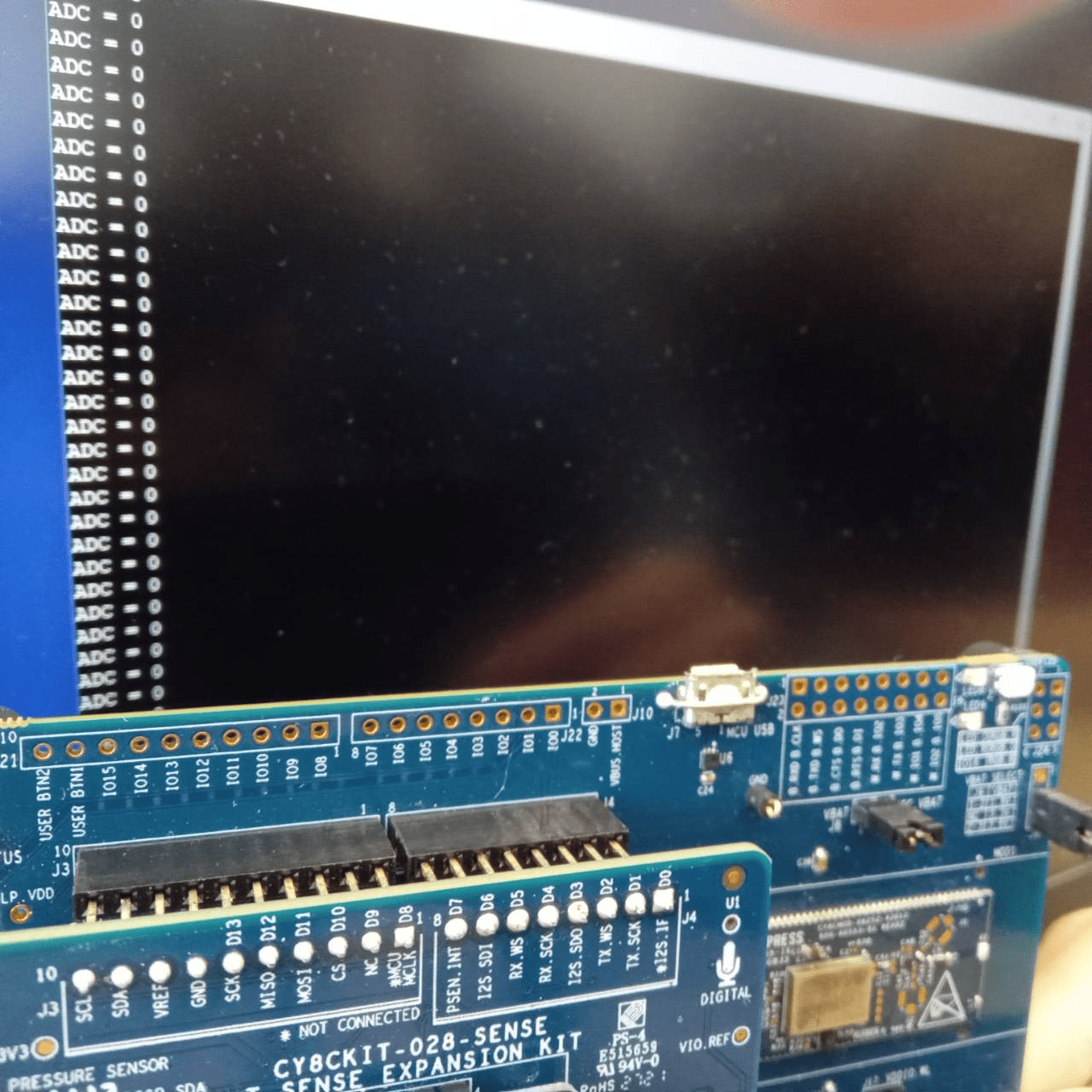
ADC = 0 ---> No LED
ADC = 1-10 ---> LED RED
# CHAPTER 2
Result
ADC = 11-20 ---> LED Blue
ADC = 21-30 ---> LED Green
END
# PRESENTING CODE
cyhal_adc_channel_init_diff( obj,adc,vplus,cfg)
cy_rslt_t cyhal_adc_channel_init_diff ( cyhal_adc_channel_t * obj,
cyhal_adc_t * adc,
cyhal_gpio_t vplus,
cyhal_gpio_t vminus,
const cyhal_adc_channel_config_t * cfg)
กำหนด ADC ช่องอื่นๆ
Parameters
[out] obj object ของช่อง ADC ที่ต้องการกำหนด
[in] adc ADC สำหรับช่องที่ต้องการกำหนด
[in] vplus input แบบ Non-inverting
[in] vminus input แบบ Inverting. สำหรับ single ended channel, ใช้ CYHAL_ADC_VNEG.
[in] cfg กำหนดช่อง ADC
#include "cy_pdl.h"
#include "cyhal.h"
#include "cybsp.h"
#include "cy_retarget_io.h"


int main(void)
{
    cy_rslt_t result;
    cyhal_adc_t adc_obj;
    cyhal_adc_channel_t adc_chan_0_obj;

    /* Initialize the device and board peripherals /
    result = cybsp_init() ;
    if (result != CY_RSLT_SUCCESS)
    {
        CY_ASSERT(0);
    }

    __enable_irq();

    / Initialize retarget-io to use the debug UART port /
    result = cy_retarget_io_init(CYBSP_DEBUG_UART_TX, CYBSP_DEBUG_UART_RX, CY_RETARGET_IO_BAUDRATE);
    CY_ASSERT(result == CY_RSLT_SUCCESS);

    / ADC conversion result. /
    int adc_out;

    / Initialize ADC. The ADC block which can connect to pin 10[6] is selected /
    result = cyhal_adc_init(&adc_obj, P10_6, NULL);

    // ADC configuration structure
    const cyhal_adc_config_t ADCconfig ={
        .continuous_scanning = false,
        .resolution = 12,
        .average_count = 1,
        .average_mode_flags = 0,
        .ext_vref_mv = 0,
        .vneg = CYHAL_ADC_VNEG_VREF,
        .vref = CYHAL_ADC_REF_VDDA,
        .ext_vref = NC,
        .is_bypassed = false,
        .bypass_pin = NC
    };

    // Configure to use VDD as Vref
    result = cyhal_adc_configure(&adc_obj, &ADCconfig);

    / Initialize ADC channel, allocate channel number 0 to pin 10[6] as this is the first channel initialized /
    const cyhal_adc_channel_config_t channel_config = { .enable_averaging = false, .min_acquisition_ns = 220, .enabled = true };
    result = cyhal_adc_channel_init_diff(&adc_chan_0_obj, &adc_obj, P10_6, CYHAL_ADC_VNEG, &channel_config);

    for (;;)
    {
        / Read the ADC conversion result for corresponding ADC channel. Repeat as necessary. */
        adc_out = cyhal_adc_read_uv(&adc_chan_0_obj);
        printf("ADC = %d\r\n", adc_out);
        cyhal_system_delay_ms(100);
    }
}
Midterm Big Home ครั้งที่ 1
By anaphat


