


He Wang PRO
Knowledge increases by sharing but not by saving.
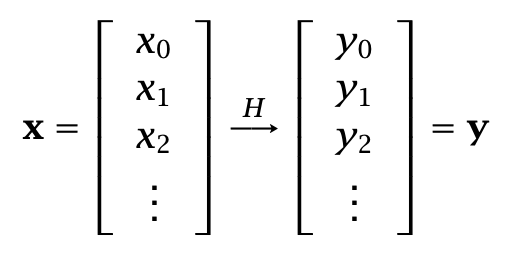
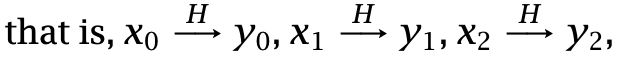
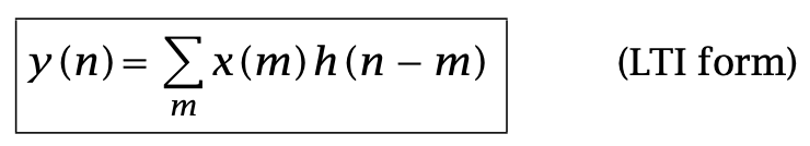
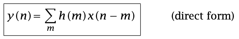
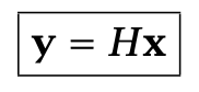
The input/output (I/O) relationship of LTI systems is given by the discrete-time convolution of the system’s impulse response with the input signal.
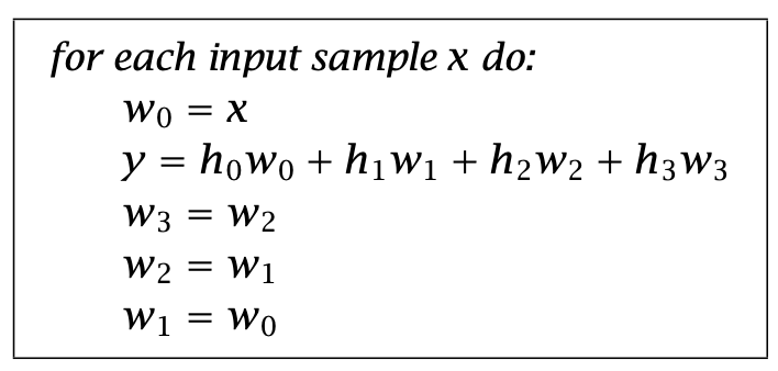
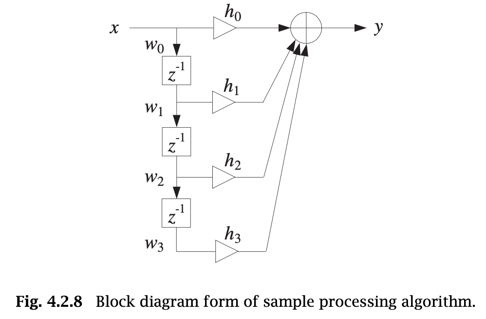
Depending on the application and hardware, an FIR digital filtering operation can be organized to operate either on a block basis or a sample-by-sample basis.
LTI systems can be classified into: finite impulse response (FIR) or infinite impulse response (IIR) types depending on whether their impulse response has finite or infinite duration.
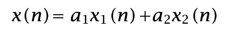
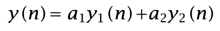
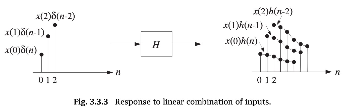
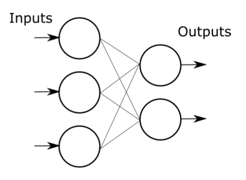
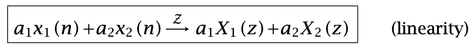
A linear system has the property that the output signal due to a linear combination of two or more input signals can be obtained by forming the same linear combination of the individual outputs.
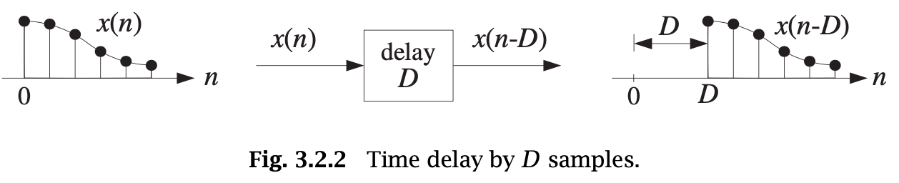
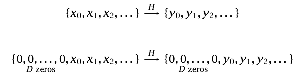
A time-invariant system is a system that remains unchanged over time.
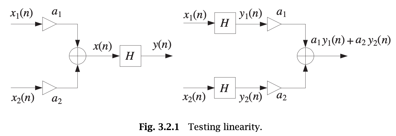
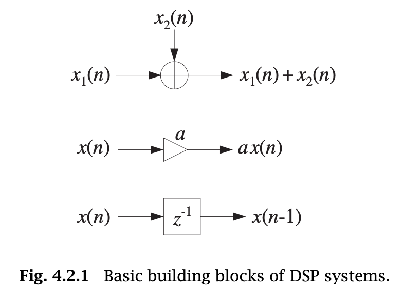
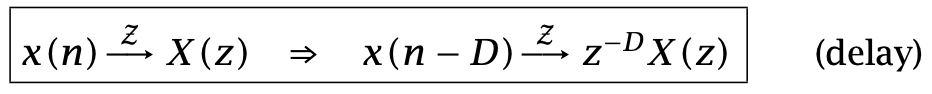
The operation of waiting or delaying a signal by a time delay of, say, D units of time is shown in Fig. 3.2.2. It represents the right translation of x(n) as a whole by D samples.
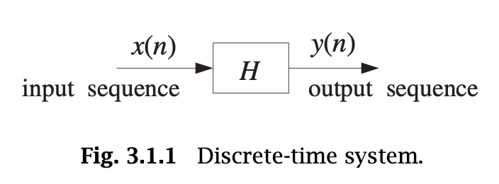
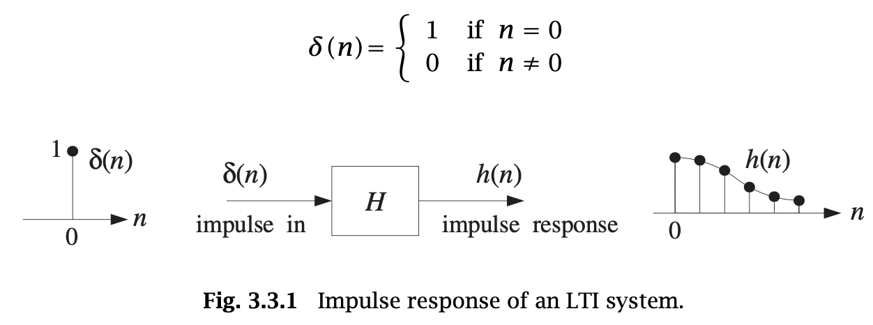
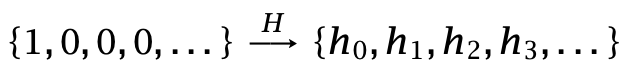
LTI systems are characterized uniquely by their impulse response sequence h(n), which is defined as the response of the system to a unit impulse δ(n), as shown in Fig. 3.3.1.
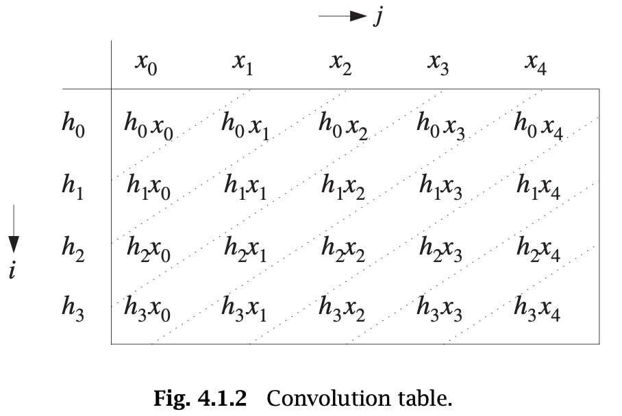
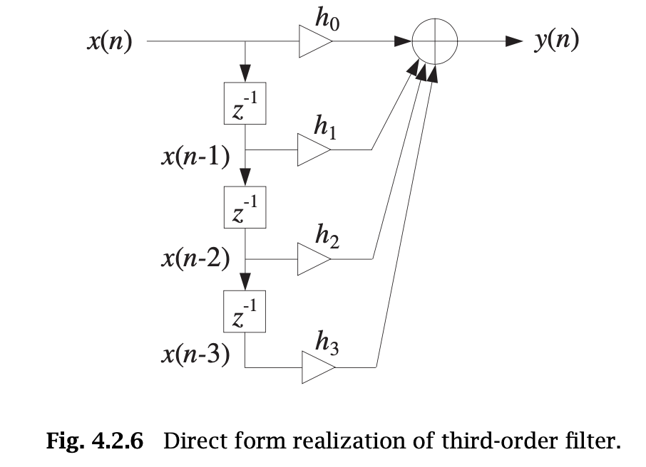
This is the discrete-time convolution of the input sequence x(n) with the filter sequence h(n). Thus, LTI systems are convolvers.
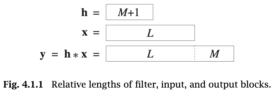
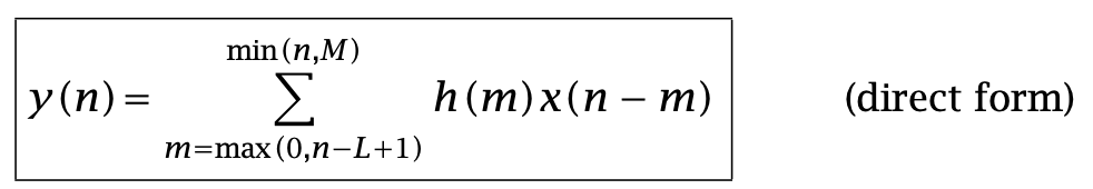
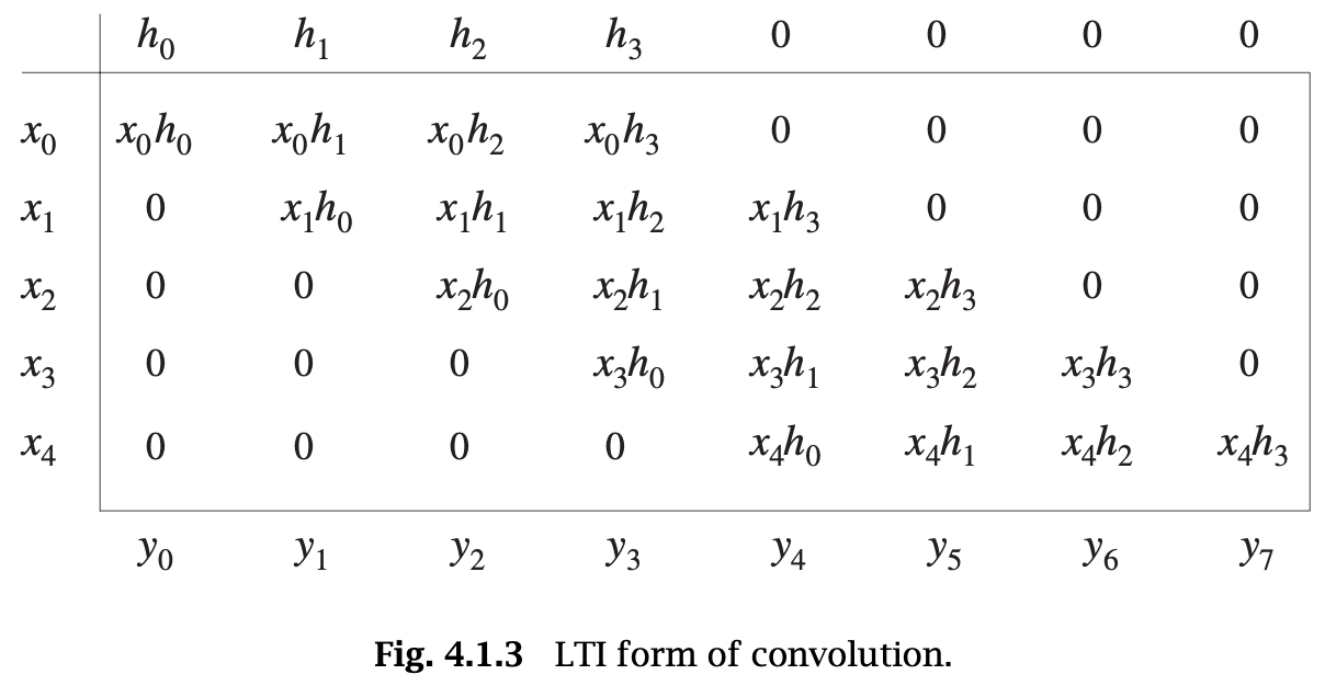
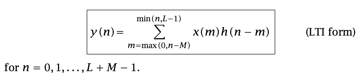
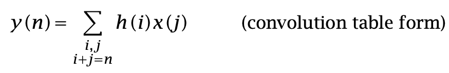
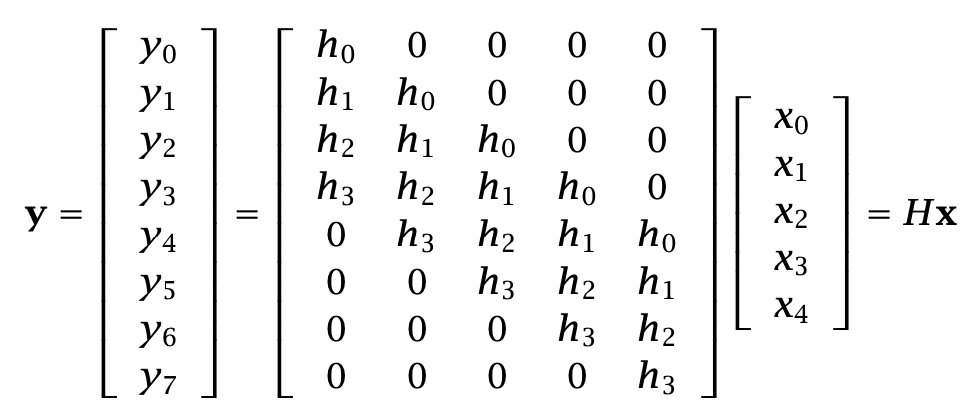
Various equivalent forms of convolution: (FIR filters and finite-duration inputs)
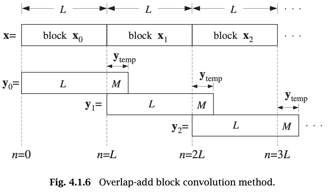
Various equivalent forms of convolution: (block-by-block and finite-duration inputs)
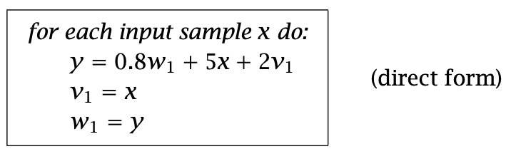
Sample Processing Methods
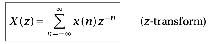
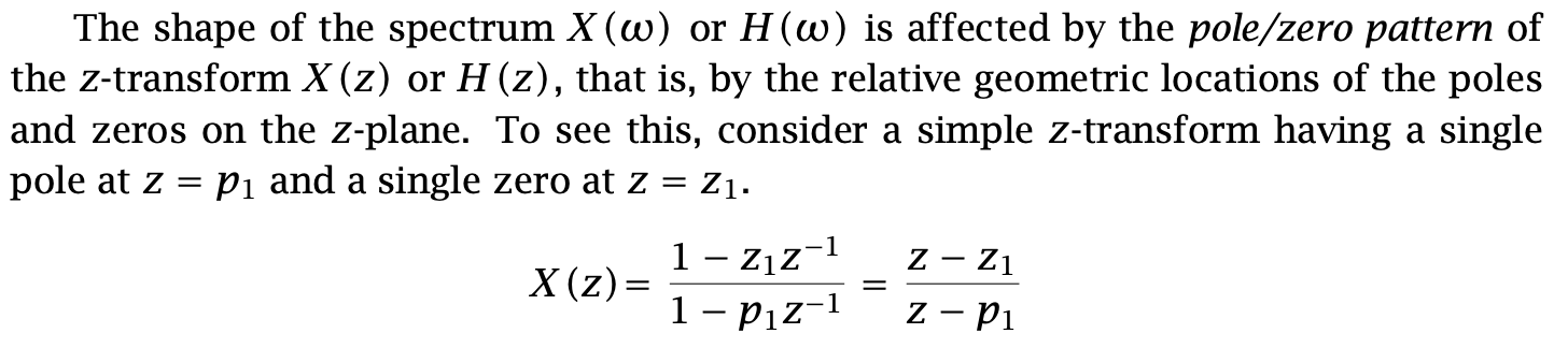
Given a discrete-time signal x(n), its z-transform is defined as the following series:
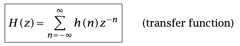
The z-transform of h(n) is called the transfer function of the filter and is defined by:
The three most important properties of z-transforms that facilitate the analysis and synthesis of linear systems are:
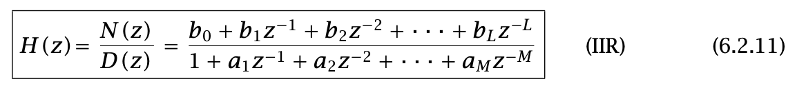
In general, the transfer function of an IIR filter is given as the ratio of two polynomials of degrees, say L and M:
Note that by convention, the 0th coefficient of the denominator polynomial has been set to unity a0 = 1. The filter H(z) will have L zeros and M poles.
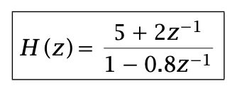
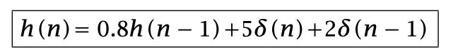
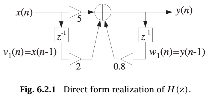
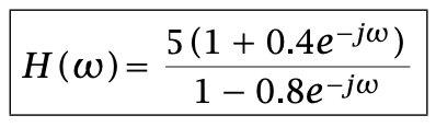
As an example, consider the transfer function:
We can obtain the difference equation for h(n):
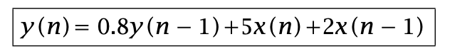
Therefore, the I/O difference equation is:
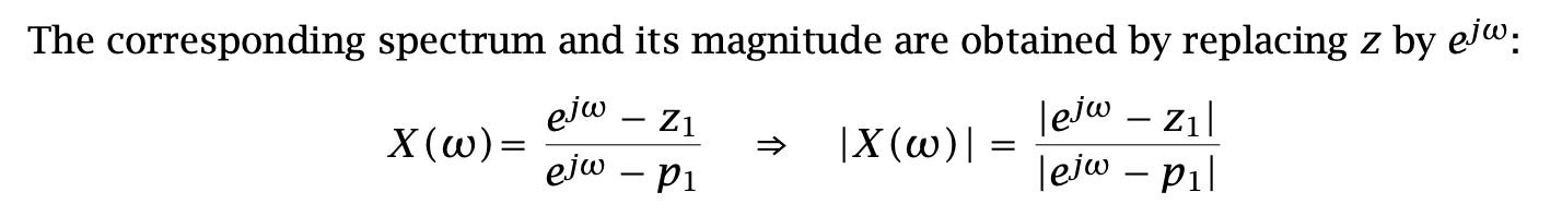
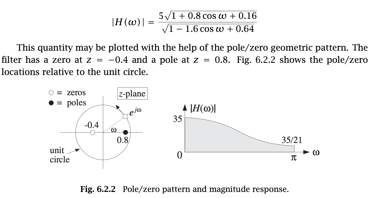
The frequency response of this filter also can be obtained:
By He Wang


