AOE 5984: Introduction to Parallel Computing Applications
OpenFOAM for CFD Applications
Lecture 4: Meshing
Professor Eric Paterson
Aerospace and Ocean Engineering, Virginia Tech
21 November 2013
Lecture 4: Meshing
- Discuss OpenFOAM native and 3rd party meshing tools
- Give overview of mesh manipulation and conversion tools in OpenFOAM
- Walkthrough of parallel mesh generation with snappyHexMesh
- Students will:
- appreciate that OpenFOAM has: two mesh generation utilities (blockMesh and snappyHexMesh); and numerous mesh-manipulation tools.
- understand that meshes can be built in other tools (e.g., Pointwise), and either directly exported to OpenFOAM format, or converted to OpenFOAM format using conversion tools
- appreciate the limited options of parallel mesh generation (e.g., in commercial mesh generators), and therefore understand the power of snappyHexMesh
CFD Process
- Formulate the problem
- Model the geometry and domain
- Establish boundary and initial conditions
- Mesh generation
- Establish simulation strategy
- Establish input parameters
- CFD simulation
- Data analysis
- Visualization
- Repeat process as needed to explore parameter space
- Documentation
Mesh generation
- The computational domain is discretized into a spatial grid.
- Mesh generation involves defining the structure and topology and then generating a grid on that topology.
- The grid should exhibit some minimal grid quality as defined by measures of orthogonality, relative grid spacing, grid skewness, etc.
- Grid clustering and sizes should be consistent with the desired resolution of important features.
OpenFOAM native tools
blockMesh
-
Algebraic mesher with command-line interface
- Great for simple problems, and tutorials
- Not useful for complex geometries
- User guide
snappyHexMesh
- Geometry prescribed using STL file
- 3D automatic meshed using hex and split-hex cells
- Fully parallelized
- User guide
Running SHM
To Run SHM, the following items are required
-
surface data file in STL format, located in constant/triSurface subdirectory
- background hex mesh which defines the extent of the computational domain and the baseline mesh density
- a snappyHexMeshDict dictionary with appropriate input parameters
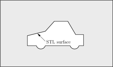
SHM: Step 1
The domain and the geometry must be defined
SHM: Step 2
Before SHM is executed, a background mesh of hex cells that fills the entire region must be generated
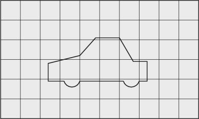
This can be done using blockMesh or any other external package.
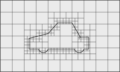
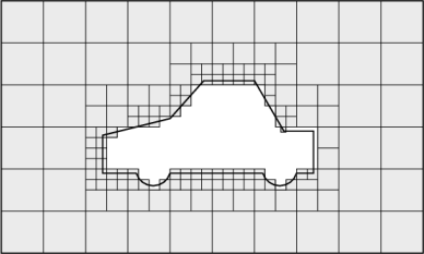
SHM: Step 3
Cell splitting begins with cells selected according to specified edge features within the domain

The features list in the castellatedMeshControls sub-dictionary permits dictionary entries containing a name of an edgeMesh file and the level of refinement
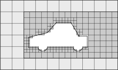
SHM: Step 4
Following feature refinement, cells are selected for splitting in the locality of specified surfaces
SHM: Step 5
Once the feature and surface splitting is complete a process of cell removal begins. Cell removal requires one or more regions enclosed entirely by a bounding surface within the domain. Cells are retained if 50% or more of their volume lies within the region
SHM: Step 6
Those cells that lie within one or more specified volume regions can be further split by a rectangular region shown by dark shading. The refinementRegions sub-dictionary in castellatedMeshControls contains entries for refinement of the volume regions specified in the geometry sub-dictionary
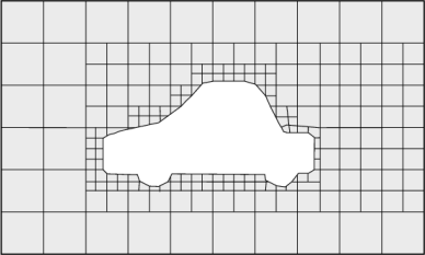
SHM: Step 7
The next stage of the meshing process involves moving cell vertex points onto surface geometry to remove the jagged castellated surface from the mesh. The process is:
- displace the vertices in the castellated boundary onto the STL surface;
- solve for relaxation of the internal mesh with the latest displaced boundary vertices;
- find the vertices that cause mesh quality parameters to be violated;
- reduce the displacement of those vertices from their initial value (at 1) and repeat from 2 until mesh quality is satisfied.
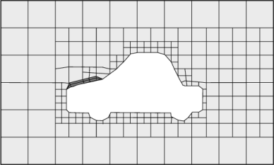
SHM: Step 8
The mesh output from the snapping stage may be suitable, although it can produce some irregular cells along boundary surfaces. There is an optional stage of the meshing process which introduces additional layers of hexahedral cells aligned to the boundary surface as illustrated by the dark shaded cells
3rd Party Meshers
-
List of public domain and commercial meshers
- Personally, I have over 20 years of experience with Gridgen/Pointwise

Pointwise
- Process is very different from SHM
- Instead of command-line, PW uses a CAD-like GUI interface
-
Mesh construction based upon:
- CAD input of geometry
- Connectors (block edges)
- Domains (block faces or surface mesh)
- Blocks (volume mesh)
- Structured and unstructured surface and volume meshes
- Nice feature is the graphical selection of boundaries and prescription of boundary conditions
-
Export to many flow solvers, including OpenFOAM
Pointwise walkthrough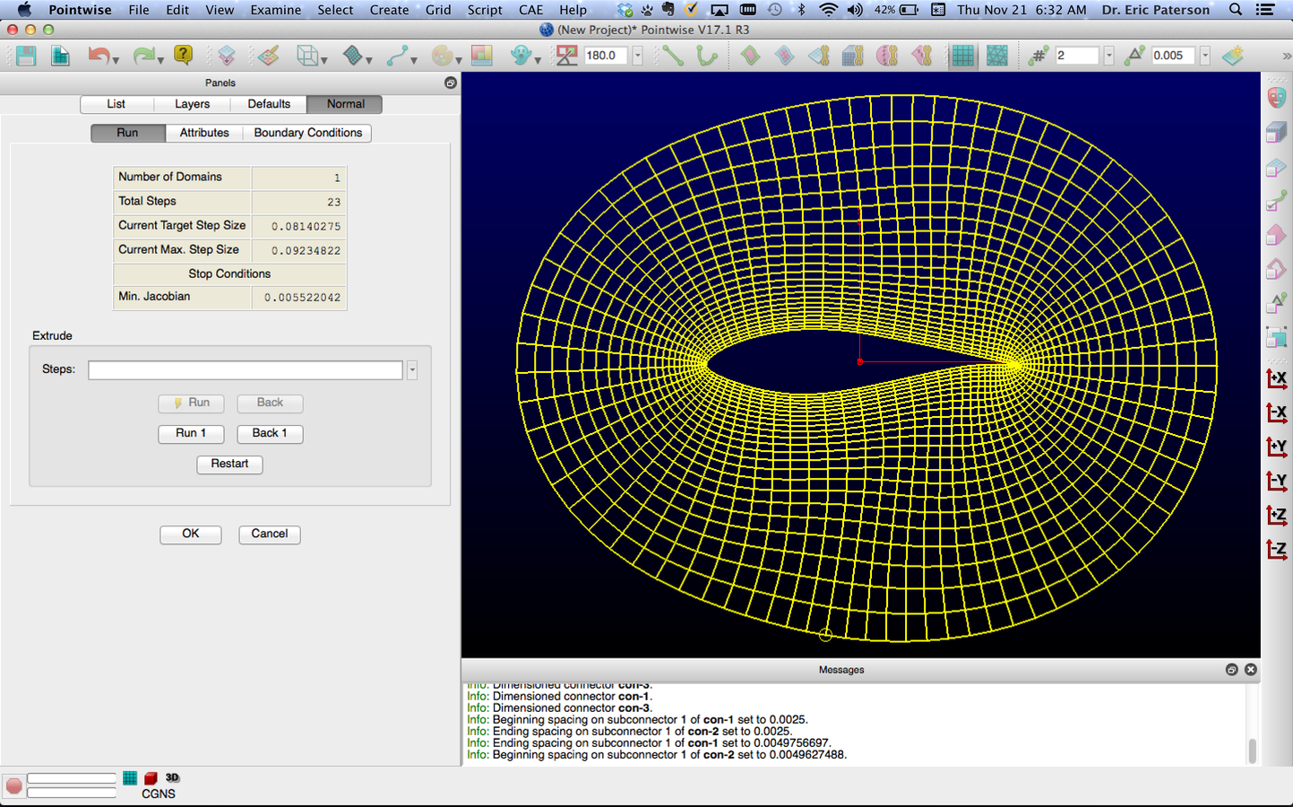

Mesh Conversion
- Numerous conversion utilities in OpenFOAM, e.g.,
- fluentMeshToFoam
- starToFoam
- gambitToFoam
- ideasToFoam
- cfx4ToFoam
-
Plus numerous utilities for mesh manipulation, e.g.,
- checkMesh - checks quality of mesh
- mergeMeshes - merge two meshes into one
- mirrorMesh - mirror across a plane
- refineMesh - refine mesh in multiple directions
- transformPoints - translate, rotate, scale
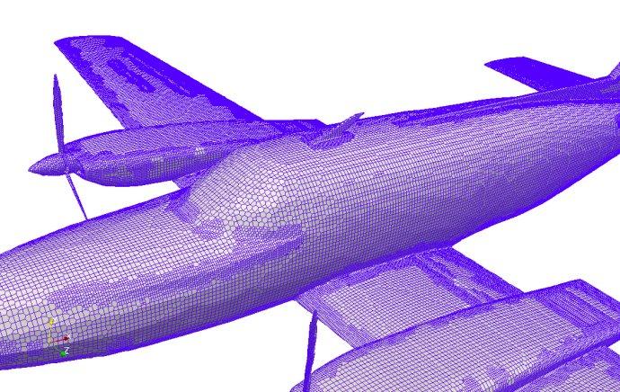
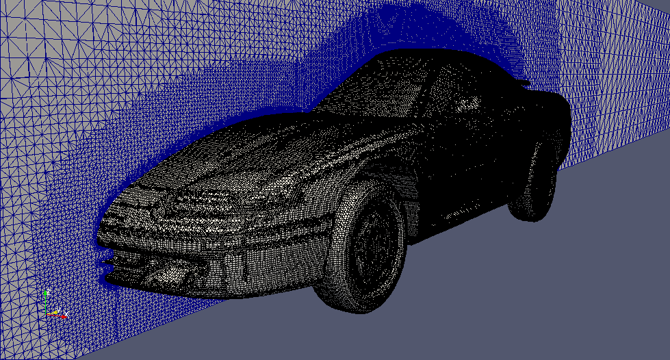
SHM Walkthrough
Build mesh for Nautilus submarine on BlueRidge
- View nautilus.stl file using Paraview
- Build background mesh using blockMesh
- Run decomposePar
- Examine snappyHexMeshDict
- Run SHM in parallel
- View each phase of mesh generation
STL surface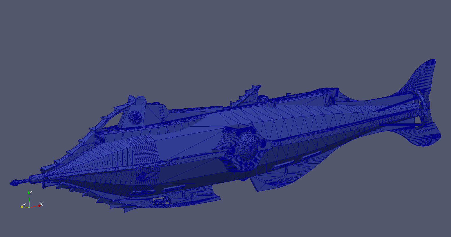
Background Mesh
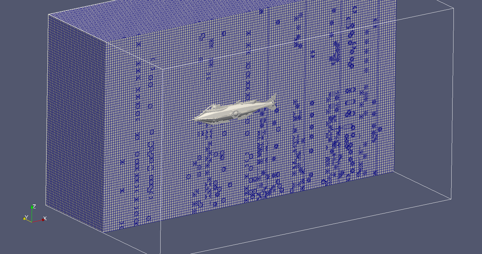
Castellated Mesh
SHM run on 64 cores on BlueRidge
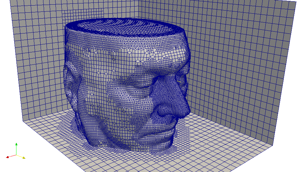
Snapped Mesh
Layers Added
Questions?
Copy of AOE 5984: OPENFOAM Meshing
By Vikram Unnithan
Copy of AOE 5984: OPENFOAM Meshing
OpenFOAM for AOE 5984, Fall 2013. This lecture will cover meshing for OpenFOAM CFD simulations.


