Data Link Layer
Dr. Alexios Louridas
Objectives
-
Interface
-
Provides an interface between network layer and transmission via the physical layer.
-
-
Frames
-
Bytes are placed together in frames.
-
-
Errors
-
Transmission errors are corrected in the data link layer.
-
-
Bottlenecks
-
Regulate how the flow of data happens to avoid slow receivers/transmitters being overwhelmed.
-
Functions

Unacknowledged connectionless
Frames are send without the source waiting to find out if it has been received successfully.
Ethernet
Error rate low
Sensitive data (Video, voice)
Services
acknowledged connectionless
Frames are sent and the source waits for an acknowledgement from the destination. Retransmission is possible.
802.11
Frame size important
Propagation delay very important
acknowledged connection-oriented
Connection is established before sending frames.
Acknowledgments expected
Connection Resource Release
Satellite and telephone links
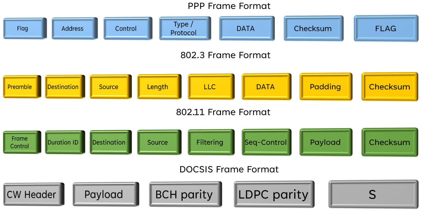
Example Frames
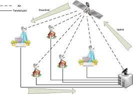
Link Types
Broadcast
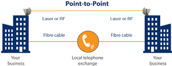
Point-to-Point
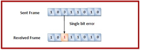
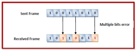
Types of Errors
Single Bit
Least Likely
Example:
Transmitting at 1 Mbps means that a bit lasts for 1 μs and thus a disruption should also be that length.
Multiple Bit
More common and usually happens in conjunction with burst errors
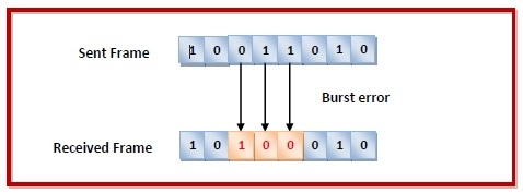
Burst
Most likely to occur.
The length of the burst is measured from the first corrupted bit to the last. In-between there might be few correct bits.
Detection and Correction
- Error Detection
- Parity Check
- Checksum
- Cyclic Redundancy Check (CRC)
- Error Correction
- Retransmission Error Correction
- Forward Error Correction
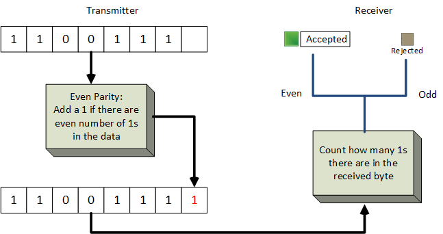
Parity Check
A parity bit is added to every data unit so that the total number of 1s is even or odd for even or odd parity check respectively
Checksum
- Convert data into a n sections of k bits
- Add all sections using ones complement to get a sum
- Complement the sum (Checksum)
- Add the complement of the sum
To calculate the checksum that we need to add:
1 0 1 0 1 0 0 1
0 0 1 1 1 0 0 1
A 16 bit block is being transmitted via UDP
1 0 1 0 1 0 0 1 0 0 1 1 1 0 0 1
Step 1
Sum: 1 1 1 0 0 0 1 0
Checksum: 0 0 0 1 1 1 0 1
Step 2
Step 3
Transmit: 1 0 1 0 1 0 0 1 0 0 1 1 1 0 0 1 0 0 0 1 1 1 0 1
Step 4
Excersices
- If you receive the following 24 bits find if you have received the first 16 bits correctly.
1 0 1 0 1 0 0 1 0 0 1 1 1 0 0 1 0 0 0 1 1 1 0 1
- If you receive the following 24 bits find if you have received the first 16 bits correctly.
1 0 1 0 1 1 1 1 1 1 1 1 1 0 0 1 0 0 0 1 1 1 0 1
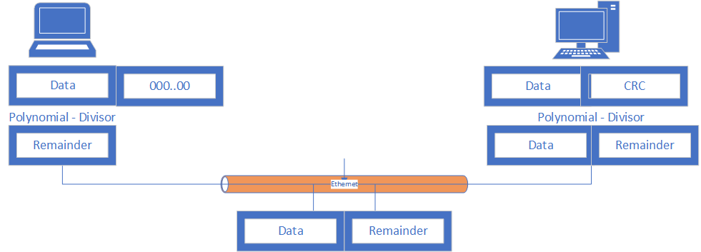
Cyclic Redudancy Check (CRC)
A checksum algorithm used to detect errors
- Sender Side (CRC Generator and Modulo Division)
- Receiver Side (Checking for errors in the received data)
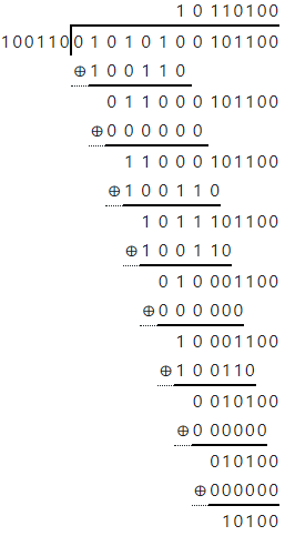
Cyclic Redudancy Check (CRC) Sender
Example: We need to send the following data: 100101011, using GSM (2G), and thus use a CRC-3 error detection with the following polynomial:
x^3+x^2+1
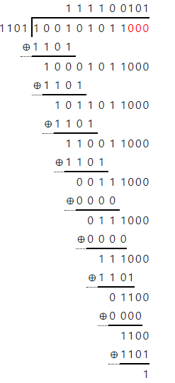
Data Converted to: 1 0 0 1 0 1 0 1 1 0 0 0
Divided by: 1 1 0 1
Quotient / Result is : 1 1 1 1 0 0 1 0 1
Remainder / CRC bits: 0 0 1
Data 100101011001 to be sent
Cyclic Redudancy Check (CRC) Receiver
Example: We need to send the following data: 100101011, using GSM (2G), and thus use a CRC-3 error detection with the following polynomial:
x^3+x^2+1
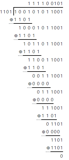
Data Received: 1 0 0 1 0 1 0 1 1 0 0 1
Divided by: 1 1 0 1
Quotient / Result is : 1 1 1 1 0 0 1 0 1
Remainder / CRC bits: 0 0 0
If remainder is zero then no error detected
EXERCISE
- You received the following data from an RFID:
0 1 0 1 0 1 0 0 1 0 1 1 0 0 - An RFID uses CRC-5 and you use the following divisor:
- Find out if you received the data without error

x^5+x^2+x
Solution
Data Received: 0 1 0 1 0 1 0 0 1 0 1 1 0 0
Divided by: 1 0 0 1 1 0
Quotient / Result is : 1 0 1 1 0 1 0 0
Remainder / CRC bits: 1 0 1 0 0
ERROR FOUND but WHERE?

Ethernet CRC-32
By default, the standard generator polynomial used by the STM32 CRC peripheral is the Ethernet CRC-32 polynomial 0x04C11DB7
x^{32} + x^{26} + x^{23} + x^{22} + x^{16} +
\\
x^{12} + x^{11} + x^{10} + x^8 + x^7 + x^5 +
\\
x^4 + x^2 + x + 1
Forward Correcting Codes
- Convolutional Codes (bit by bit)
- Viterbi
- Block Codes (block by block)
- Hamming Code
- Reed-Solomon
- Turbo Codes
-
(7,4)
-
4 bits with 3 extra bits
-
-
(15,11)
-
11 bits with 4 extra bits
-
-
(31,26)
-
26 bits with 5 extra bits
-
-
(63,57)
-
64 bits with 6 extra bits
-
-
(255,247)
-
255 bits with 8 extra bits
-
-
All Detect 2 bits and correct 1 bit
Hamming Codes
Hamming (7,4) code
01010100010100100100100010
You have a stream of bits
Divide it in 4 bit words
0101\\
0100\\
0101\\
0010\\
0100\\
1000
x\;y\;z\\
x\;y\;z\\
x\;y\;z\\
x\;y\;z\\
x\;y\;z\\
x\;y\;z\\
To calculate x, y and z we can use the following formulas:
\color{red}x=a\oplus b\oplus d \\
\color{green}y=a\oplus c\oplus d \\
\color{blue}z=b\oplus c\oplus d
\color{red}{a\;b\;c\;d\;}\color{blue}{x\;y\;z}
Hamming (7,4) code eXAMPLE
01001000\;01100101\;01101100\;01101100\;01101111\;
An alien found voyager and decided to send a message
What should we receive?
To calculate x, y and z we can use the following formulas:
\color{red}x=a\oplus b\oplus d \\
\color{green}y=a\oplus c\oplus d \\
\color{blue}z=b\oplus c\oplus d
\color{red}{a\;b\;c\;d\;}\color{blue}{x\;y\;z}
0100\;101\\
1000\;110\\
0110\;110\\
0101\;010\\
0110\;110\\
1100\;011\\
0110\;110\\
1100\;011\\
0110\;110\\
1111\;111
Solution
Hamming (7,4) code eXAMPLE Cont
Instead your receive the following:
Detect the errors and correct where possible?
To detect errors use deduction of these equations
\color{red}x=a\oplus b\oplus d \\
\color{green}y=a\oplus c\oplus d \\
\color{blue}z=b\oplus c\oplus d
\color{red}{a\;b\;c\;d\;}\color{blue}{x\;y\;z}
0100\;101\\
0000\;110\\
0110\;110\\
0001\;010\\
0110\;010\\
1110\;011\\
0110\;100\\
1101\;011\\
0110\;111\\
1111\;111
\begin{array}{|c|c|c|}
\hline
\text{Check Bits} & \text{Error Stat} & \text {Message + Check-bits}\\
\hline
\color{green}{x\;y\;z} & \text{No Errors} & \color{green}{a\;b\;c\;d\;x\;y\;z}\\
\color{red}{x}\color{green}{\;y\;z} & \text{Error in } \color{red}{x} & \color{green}{a\;b\;c\;d\;}\color{red}{x\;}\color{green}{y\;z}\\
\color{green}{x\;}\color{red}{y}\;\color{green}{z} & \text{Error in } \color{red}{y}& \color{green}{a\;b\;c\;d\;x\;}\color{red}{y\;}\color{green}{z}\\
\color{green}{x\;y\;}\color{red}{z} & \text{Error in } \color{red}{z} & \color{green}{a\;b\;c\;d\;x\;y\;}\color{red}{z}\\
\color{red}{x\;y\;}\color{green}{z} & \text{Error in } \color{red}{a} & \color{red}{a\;}\color{green}{b\;c\;d\;x\;y\;z}\\
\color{red}{x\;}\color{green}{y\;}\color{red}{z} & \text{Error in } \color{red}{b} & \color{green}{a\;}\color{red}{b\;}\color{green}{c\;d\;x\;y\;z}\\
\color{green}{x\;}\color{red}{y\;z} & \text{Error in } \color{red}{c} & \color{green}{a\;b\;}\color{red}{c\;}\color{green}{d\;x\;y\;z}\\
\color{red}{x\;y\;z} & \text{Error in } \color{red}{d} & \color{green}{a\;b\;c\;}\color{red}{d\;}\color{green}{x\;y\;z}\\
\hline
\end{array}
Hamming (7,4) code error table
| Error Correction | Complexity | Efficiency |
|---|---|---|
| Hamming | Low | High (single) Low (Burst) |
| Reed-Solomon | Medium | High (Burst) |
| Convolutional coding | High | High (Burst) |
| Low-Density Parity-Check | Medium | Extreme (Burst) |
| Turbo Code | Very High | Very High (Burst) |
| Polar code | Low | Extreme (Burst) |
Error correction Algorithms
-
FEC performance
-
Available Resources
-
Processing Constraints
-
Code Rate
-
Block Size
-
Complexity
-
Type of Application
Choice of FEC

| Technology | Error Correction | Error Detection |
|---|---|---|
| Memory | Hamming, Parity, Chipkill | Parity Checking |
| Etrhernet | Reed-Solomon | CRC |
| 802.11n | Convolutional coding | Checksum |
| 802.11ac | Low-Density Parity-Check | Checksum |
| 5G | Polar Coding | Block-wise CRC |
| Satellite | Hamming Coding, Convolutional Coding, Reed-Solomon Coding, and Turbo Coding. | Error Correction |
Error Algorithms in real life
Create a CRC-8 algorithm in C using 167 for your polynomial. Test your code by supplying some test data.
GOOD LUCK!!
We shall provide a solution next week.
Homework
Layer Communications
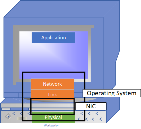
- Layers
-
Independent
-
Unidirectional Communications
- Reliable
-
Unidirectional Communications
-
Independent
- Transmission
- Packet from Network
- Encapsulation of packet to frame
- Frame only in link layer
- Encapsulation of packet to frame
- Packet from Network
-
Physical Layer
-
Shared
-
Collision if two nodes transmit at the same time
-
-
Need a flow algorithm (protocol) on sharing
-
Multiple Access Protocols
-
Multiple Access


Ideal multiple access protocol
Assumptions:
Channel has available datarate of X bps
- Node transmits at rate X
- If N nodes want to transmit, each can send at average rate X/M
- No transmissions coordination
- No synchronisation
- Not realistic
Mac Protocols
Partitioning
Divide bandwidth
Time
Frequency
Code
Random Access
Allow anyone to send information with rules.
Collisions do happen
Recover from collisions
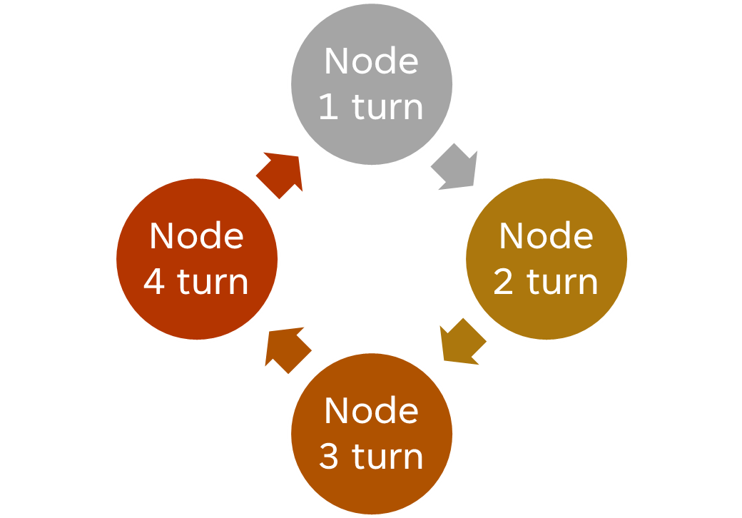
Round Robin
Mac Protocols Examples
Partitioning
FDMA
CDMA
TDMA
Random Access
Aloha
Slotted Aloha
CSMA
CSMA/CD
Round Robin
Polling
Token Ring
Bluetooth
FDDI
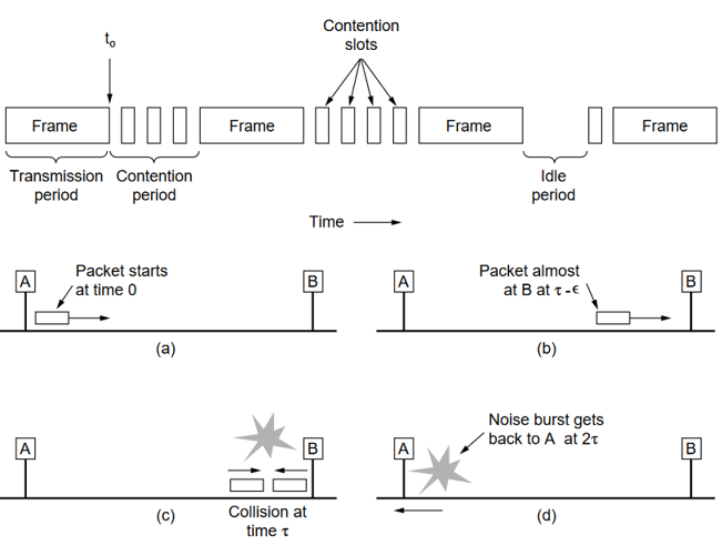
- Transmission
-
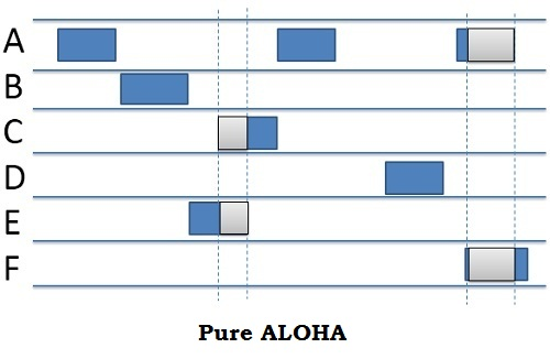
Send when a user has a frame to send.
-
- Collisions
-
A collision occurs when two frames and more share some of the time slot. It is important to make the frames of equal size.
-
- Listening
-
Detecting collision happens when the destination resends the frame. If the source listens to it then it knows that it has been received. For some systems like satellite communications the delay can be over 200ms.
-
- Retransmission
-
If collision occurs, the source waits for a random period of time and re-sends it again. The random period of time is essential to avoid colliding with the same frame.
-
Pure Aloha
Slotted Aloha
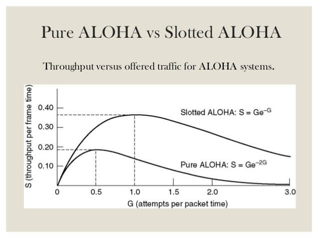
Pure Aloha Performance
Best Channel utilisation is 18% when everyone is transmitting
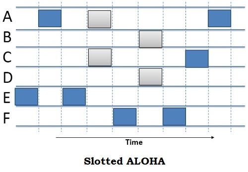
Slotted Aloha
The channel is divided into time slots. You can only transmit in certain time periods.
Slotted Aloha Performance
Channel utilisation of 37%. This is double of pure aloha.
Carrier Sense Multiple Access Protocols (CSMA)
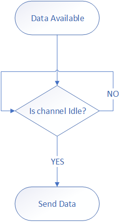
1-Persistent
You send the moment the channel is idle.
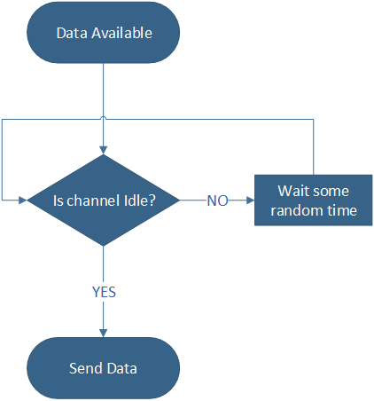
NON Persistent
Listen every t seconds and transmit if channel is idle.
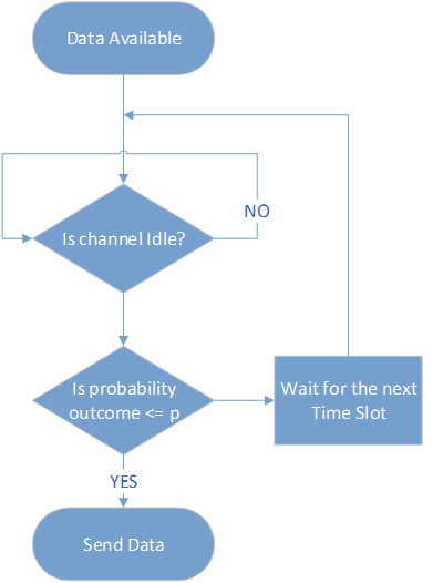
P-persistent
Listen on your time slot and either send or wait for the next timeslot.
May transmit with probability p or may defer until next slot with probability 1-p
A node is always listening. Before sending it makes sure no one is transmitting.
CSMA Operation
1-Persistent
Non Persistent
P-Persistent
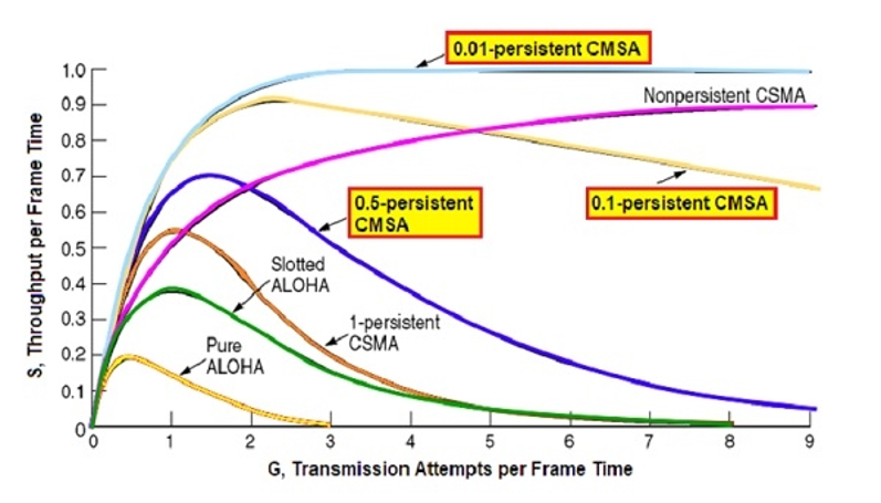
Comparisons of Random Access Protocols
-
Delay
-
Sensing delay or detection is very much dependent on the receiver. But the propagation delay on the channel is important to detect a collision or a transmission.
-
-
Throughput vs Load
-
As p becomes smaller (less greedy) the throughput is increased in high loads.
-
-
Trade-off
-
The smaller p the larger the delay (the longer the user must wait for transmission).
-
-
Increase Performance
-
If while transmitting you can also listen you can increase performance. CSMA/ Collision Detection (CSMA/CD).
-
CSMA Final Thoughts

-
Operation
-
Uses 1-Persistent algorithm, but while transmitting if it listens a collision it stops transmitting and wait a random period before it starts again.
-
-
States
-
Transmission period
-
Contention period
-
-
Collision Detection (CD)
-
Worst case time of detecting a collision is twice the propagation delay.
-
CSMA/CD
-
Classic vs Switched
-
CSMA/CD is used in all classic ethernet together with binary exponential backoff, or if we use a HUB!!!
-
-
Switches (Fast Ethernet)
-
Switches map each port and makes certain that it does not broadcasts frames where they are not needed. (These do not include the old type of switches)
-
-
Backward compatibility
-
Fast Ethernet still needs to support half duplex so still supports CSMA/CD just reduce cable size to be able to detect collisions.
-
Ethernet

-
Carrier Extension
-
A frame needs to be at least 512 bytes in order to be backwards compatible to detect collisions. This means that we can have a cable efficiency of as low as 9%.
Do not forget that an ethernet packet can be between 64 Bytes – 1518 Bytes
-
-
Frame Bursting
-
We can add more than one frame to reach the 512 bytes.
-
-
Jumbo Frames
-
Some NICs and switches allow jumbo frames which are frames longer than 1500 bytes up to a maximum of 9KBytes.
Note that Jumbo Frames are not part of the 802.3 standard.
-
-
10 Gigabit and higher Ethernet
-
All ethernets higher than 10Gbps support only full-duplex operation so CSMA/CD are no longer needed.
40Gbps and 100Gbps ethernet (802.3cd) can be targeted for Virtual Private LAN to connect to data centres.
-
Gigabit Ethernet

-
Half Duplex
-
Radios are half duplex very rarely you would have a full duplex due to received power being lowered from transmitted.
-
-
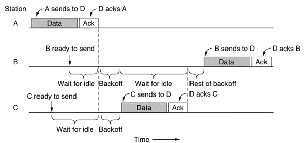
CSMA/CA
-
As receiver power is low means that collisions might not be or cannot be detected, so CSMA/CD cannot be implemented. Instead we use Collision Avoidance
-
-
Modes of Operation
-
There are two modes of operation:
1) Distributed Coordination Function (DCF) (no central control)
2) Point Coordination Function (PCF) (Access point controlled)
-
-
Multiple Mechanisms to help CSMA/CA
-
Reliability: Lower bitrate and short frames(fragments)
-
Low Power: Beacon frames (power-save modes), Automatic Power Save Delivery (APSD)
-
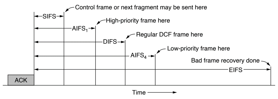
Quality of Service: Spliting time frames, DCF Interframe Spacing (DIFS), Short InterFrame Spacing (SIFS), Arbitration Interframe Spacing (AIFS), Extended Interfrmae spacing (EIFS)
-
WIFI 802.11

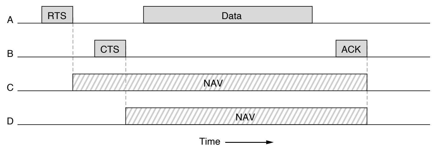
802.11 Virtual Channel Sensing using CSMA/CA
802.11 Data Link Protocols
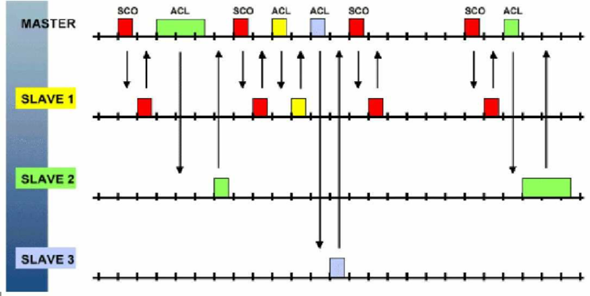
Bluetooth polling
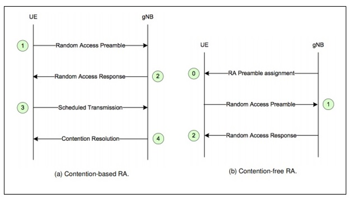
5G Mobile Random Access Channel (RACH)
- Hub
-
Connects devices together, broadcast frames on all ports.
-
- Switches
-
Store and forward ethernet frames, its transparent and PnP.
Selectively forward via examining incoming frame’s MAC address, frame to one-or-more outgoing links when frame is to be forwarded on segment, uses CSMA/CD to access segment.
-
- Auto Learning
-
Learns which hosts can be reached through which interfaces. Stores everything in a MAC address table
-
- Process
-
Record incoming link, MAC address of sending host.
-
Index switch table using MAC destination address.
-
Send to destination if found in table or flood to find and record new destination.
-
Summary - Data Link Devices
Data Link Layer
By Alexios Louridas


