DISTRIBUTION OF COMMON-VOLUME LEO-BASED AND GROUND-BASED GNSS IONOSPHERE OBSERVATIONS
Brian Breitsch
Advisor: Dr. Jade Morton


-
Geometry and Observation Volumes
- Ground
- Low Earth-Orbiting
- Method
- Common-Volume Results
- Conclusions and Future work
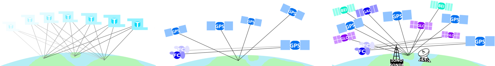
Ground-based
- CSU GPS Lab high-rate GNSS data collection sites
- e.g. Poker Flat, Alaska; Jicimarca, Peru
- receiver networks
- CORS, MONITOR, etc.
Low earth-orbiting (LEO) satellite-based
- Radio Occultation (RO) missions:
- CHAMP, COSMIC
GNSS Data
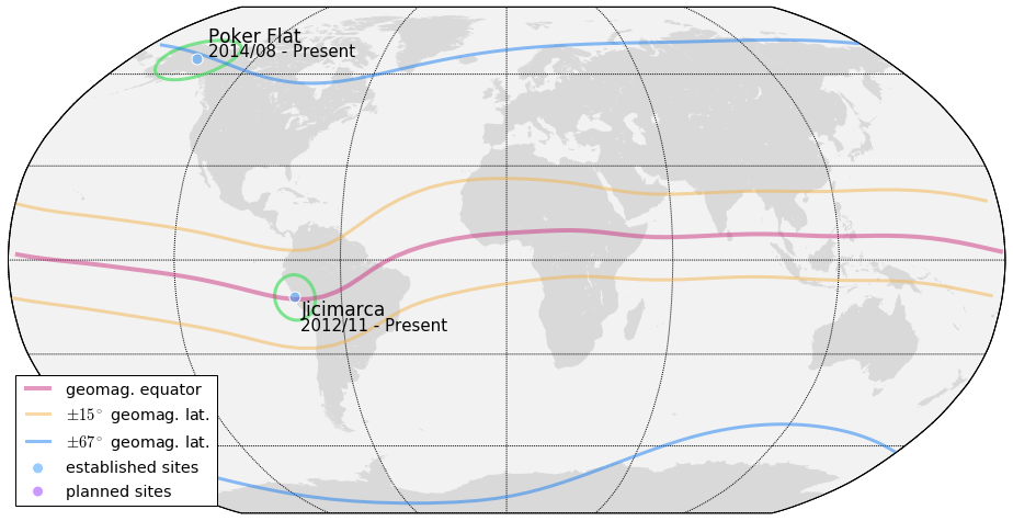
We will use Alaska and Peru to exemplify high and low-latitude geometries
Assumptions
- SGP4 for COSMIC
- accuracy generally better than 1km
-
SP3 for GNSS
- polynomial interpolation of precise orbit

- model signal propagation paths as straight line segments
- no restriction on visibility aboard COSMIC platform
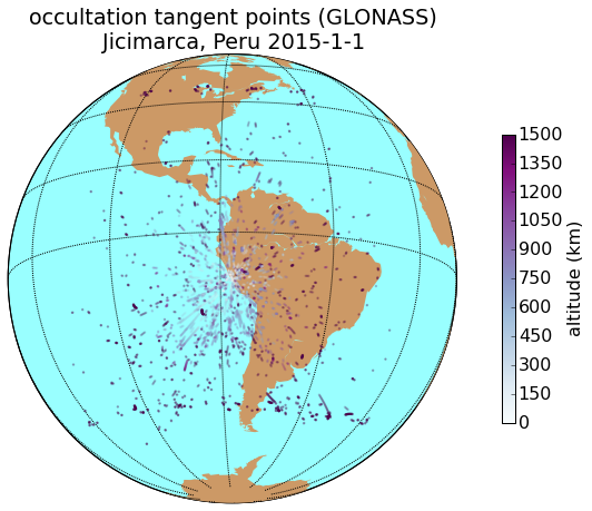
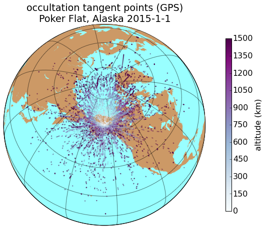
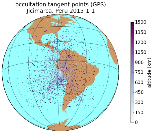
Ground-based
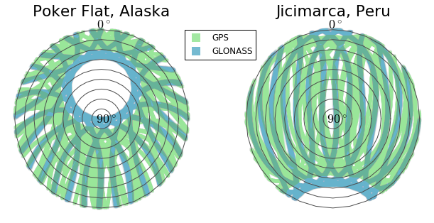
Higher orbital inclination of GLONASS satellites results in better coverage at the poles.
| orbital radius | orbital inclination | |
|---|---|---|
| GPS | 26,560 km | 55 degrees |
| GLONASS | 19,140 km | 65 degrees |
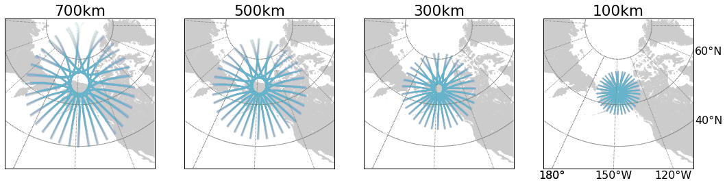
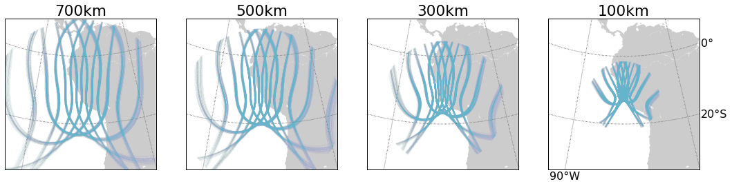
Ground observations

GLONASS
GPS
Alaska
Peru
ionosphere piercing point for various IPP heights
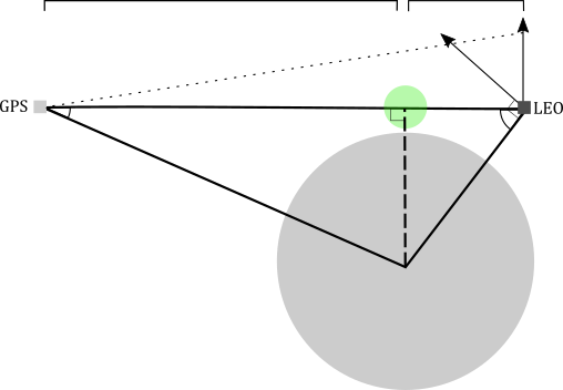
RO Tangent Point
orbital altitude: between 700-800 km
orbital inclination: 72 degrees
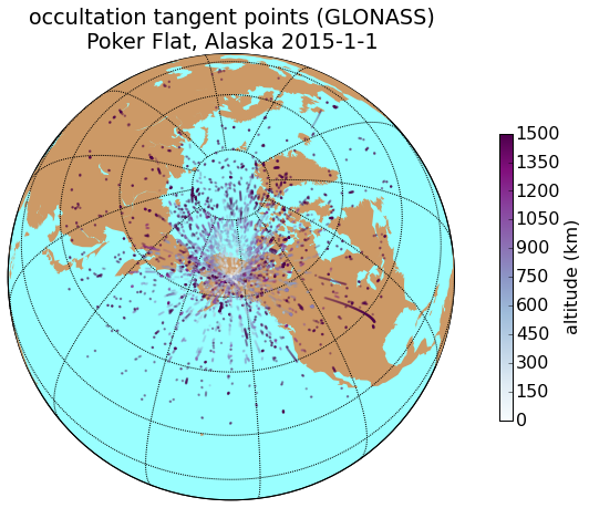
occultation tangent point (TP)
We use "occultation tangent point" as proxy for RO observation volume.
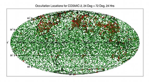
COSMIC Tangent Point Distribuion
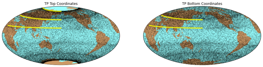
2014 March-May 90-day scatter of COSMIC-GPS occultation tangent points. Fringes of occultations appear at 72, 45, and 21 degrees due to orbital inclination and satellite geometry.
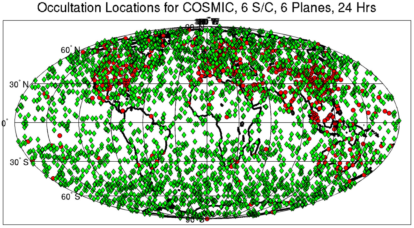
Image from UCAR showing 24-hour COSMIC occultation tangent point occurence.
http://www.cosmic.ucar.edu/

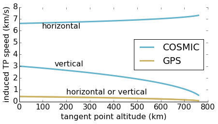
COSMIC (LEO-based)
horizontal TP speed proportional to
vertical TP speed proportional to
||v_{SV}||
||v_{SV}||\cos\theta_{SV}
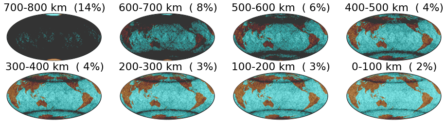
Vertical TP Distribution
90-day scatter and histogram of COSMIC-GPS independent (>100km spatial separation) occultation tangent points. Fringes result from satellite geometry. Large percentage of high-altitude occurrences due to TP speed induced by satellite motion.
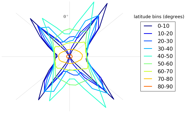
TP Azimuth by Latitdue
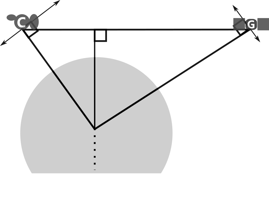
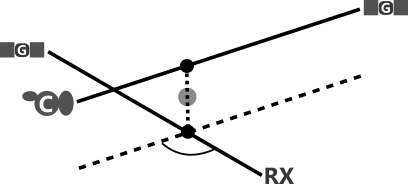
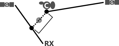
Geometry
common observation volume
RO tangent point
region of interest (ROI)
Common-Volume
Method
- compute "3D intersections" for all ray-path pairs
- screen results to find valid common-volume observations
1 receiver
6 COSMIC satellites
32 GPS satellites
1 \cdot 32 \cdot 6 \cdot 32 = 6144
(but most of them we don't care about...)

possible common-volume geometries
at every moment
example with GPS only
3D Line-Segment Intersection
-
point-of-interest (POI)
- midpoint b/w points of closest approach
-
proximity
- distance b/w points of closest approach
"the points of closest approach between two line segments"
*must handle special case where point of closest approch is on segment endpoint.
Mask/Filters
- GPS 1 (for RX) elevation > threshold (5 degrees)
- closest approach of LEO ray-path to Earth surface > 2 km altitude
Ray paths through Earth
- proximity < threshold (100 km)
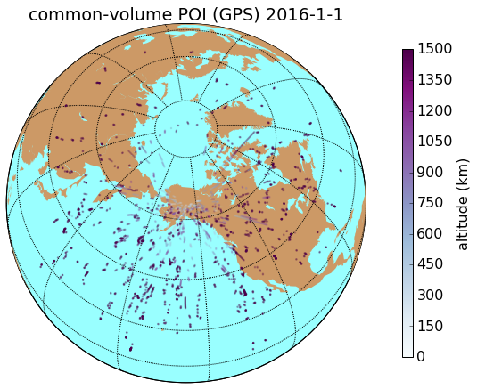
- POI altitude < threshold (1500 km)
Volumes way out in space
Results
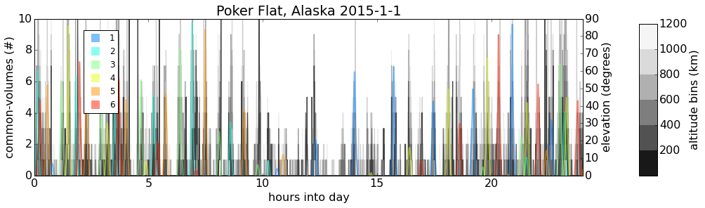
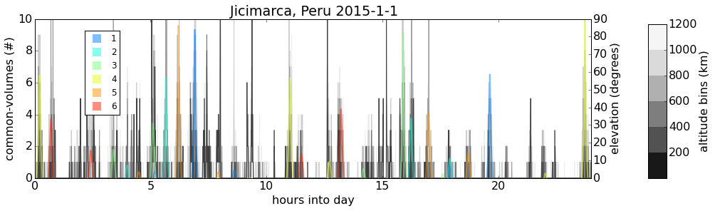
GPS
GLO
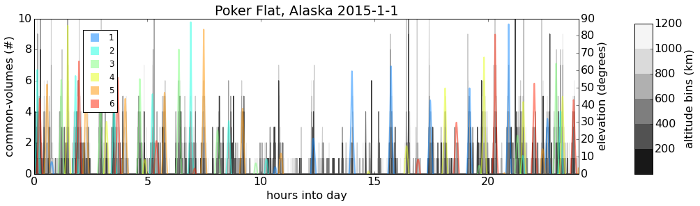
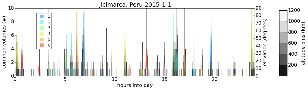
Temporal occurrences of common-volume observations (gray/black) along with COSMIC satellite elevation (color).
Results
GPS
Sharp spikes in common-volume occurrences correspond to COSMIC ray-path passing near ground receiver location.*
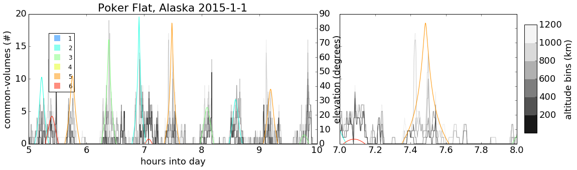
*This was verified for several cases using custom 3D common-volume visualization
Results
GPS
GLO
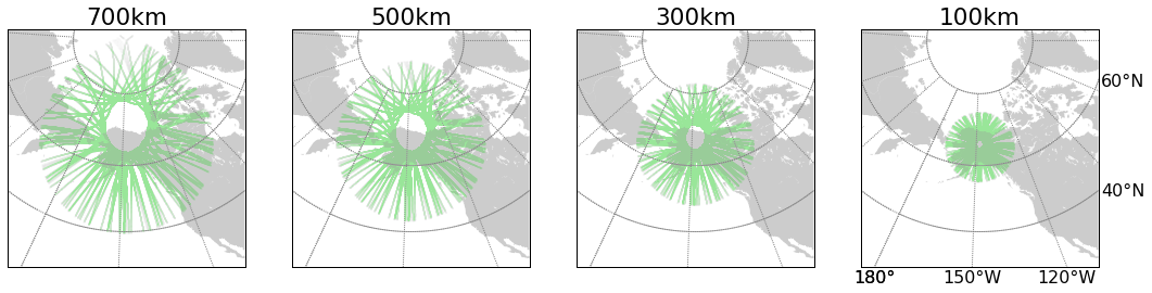
Alaska
Peru
COSMIC 1
images originally published at www.cosmic.ucar.edu
Occultation occurrences over 24 hours for COSMIC and COSMIC-2
COSMIC 2
Results
Alaska
Peru
COSMIC 2

Conclusions
- High-latitude ground receivers see periodic common-volume occurrence corresponding to COSMIC orbital period
- Low-latitude see a-periodic occurrences
- Low-altitude common-volume POIs occur near the ground receiver
- There are "poleward deficits" of common-volume occurrences at low-elevation for low-latitude and mid-to-high elevation for high-latitude
- Sharp spikes in our common-volume metric correspond to ray-path passes close to a receiver
COSMIC 2 fixes this
Motivation and Future Work
Where can we have improved imaging resolution in the ionosphere
Adaptive-mesh tomographic imaging of ionosphere electron density
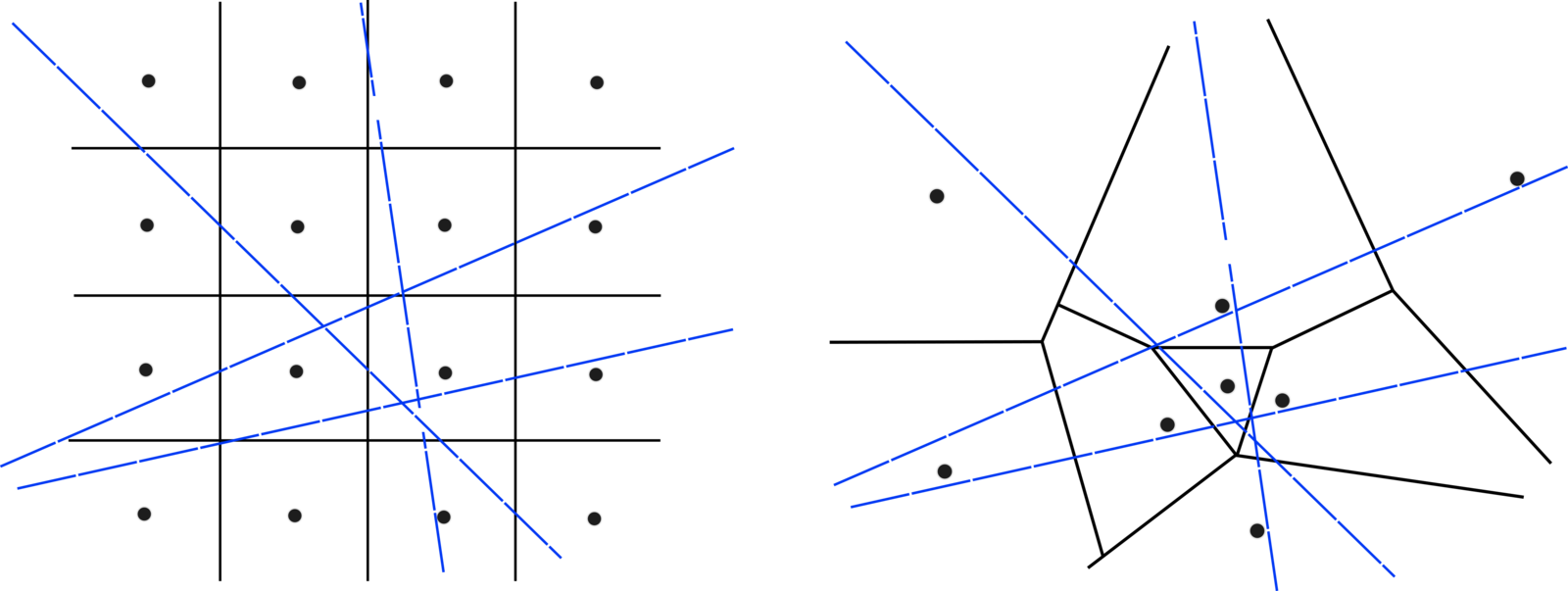
Ionosphere Tomography
Acknowledgements
This research was supported by the Air Force Research Laboratory and NASA.
References
- TS Kelso et al. Validation of sgp4 and is-gps-200d against gps precision ephemerides. 2007
-
"COSMIC-2." COSMIC 2. UCAR, n.d. http://www.cosmic.ucar.edu/cosmic2. 02 Jan. 2016.
-
Chen-Joe Fong et. al. Formosat-3/COSMIC spacecraft constellation system, mission results, and prospect for follow-on mission. 2009.
COSMIC and GNSS Common-Volume Observations
By Brian Breitsch


