Ionosphere Observability Using GNSS and LEO Platforms
Brian Breitsch
Advisor: Dr. Jade Morton


- Motivate ionosphere TEC observations
- Past work in ionosphere observability
-
Observation volume
- Ground receivers
- LEO radio occultations (RO)
- Joint ground and LEO overhead/RO
- LEO beacons
- Data affects in simulated localized imaging
Image credit: NASA/J. Grobowsky 2014
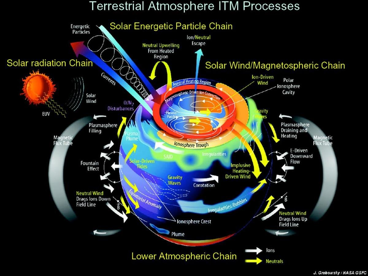
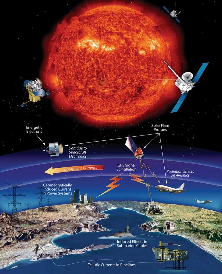
Image credit: NASA
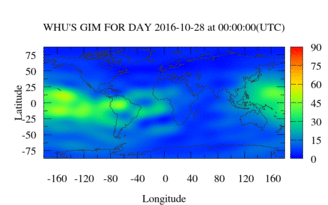
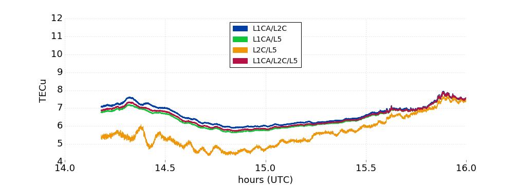
Ionosphere TEC
TEC = \int_{\text{rx}}^\text{sat} N_e(x) dx
observed by multi-frequency GNSS
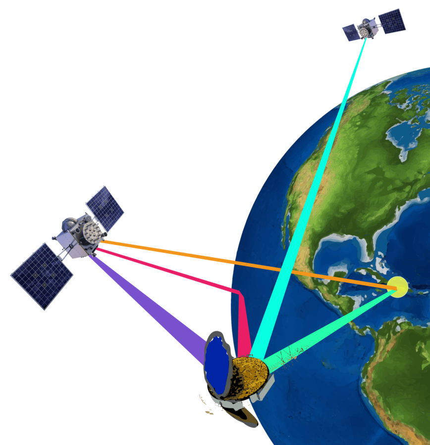
LEO reflection
LEO occultation
LEO beacon
ground GNSS
LEO overhead
low Earth-orbiting (LEO)
Global Navigation Satellite System (GNSS)
Previous Work
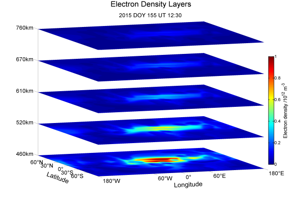
- 2D and 3D ionosphere maps of electron density from TEC measurements
Image Credit: "Multi-satellite ionosphere-plasmasphere
electron density reconstruction", GFZ Potsdam
- climatological and large-scale
Wang Yang
"Observing System Simulation Experiment Study on Imaging the Ionosphere by Assimilating Observations From Ground GNSS, LEO-Based Radio Occultation and Ocean Reflection, and Cross Link"
Previous Work
Xinan Yue et. al. 2013
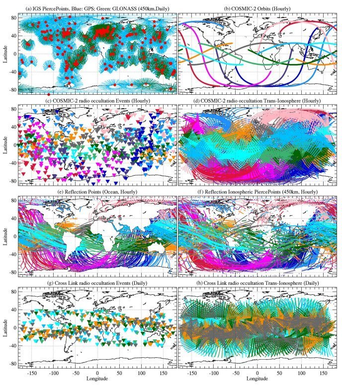
- LEO occultations largely contribute to global-scale models due to lack of ground RX over oceans
GNSS Ground Receivers
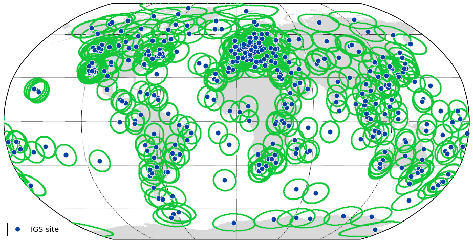
GPS Lab
High-rate GNSS data collection network
IGS
Station Map
GNSS network data available from many sources: IGS, CORS, ARGN, etc.
Ground RX Observations
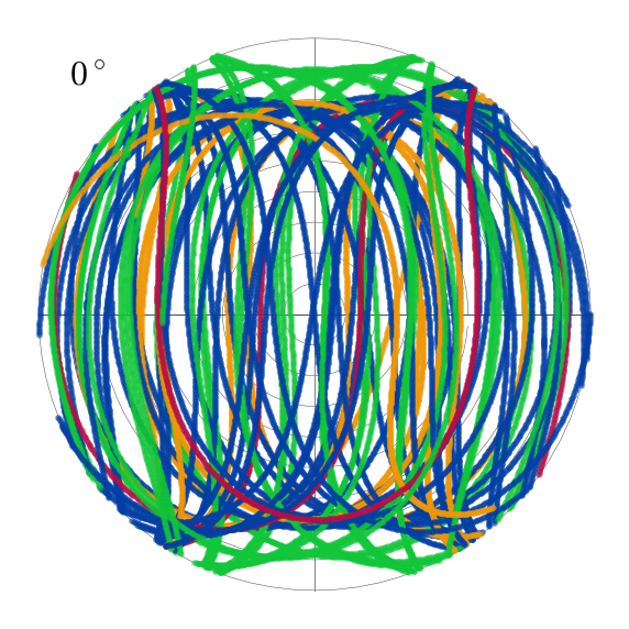
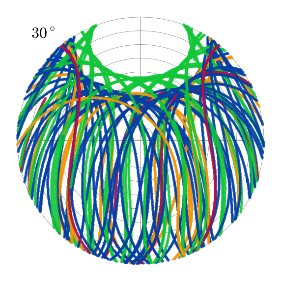
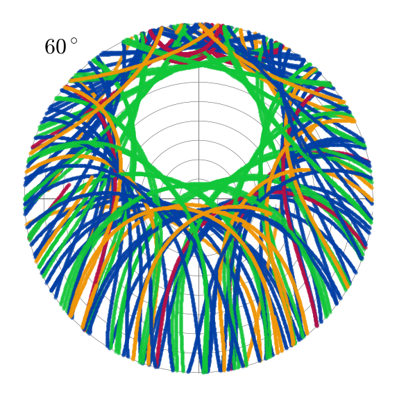
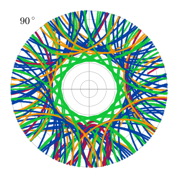
GNSS sky plots
Ground RX Observations
700 km
400 km
100 km
60°
30°
0°
GNSS signal ionosphere piercing points for ground receiver at low/mid/high latitude
5° elevation mask
IPP
LEO Receiver Observations
orbital altitude: between 500-800 km
orbital inclination: 24° or 72°
occultation tangent point (TP)
e.g. COSMIC/COSMIC-2

- use POD antenna
- highly localized to LEO satellite
- use occultation antennas
- traverse large ionosphere volume
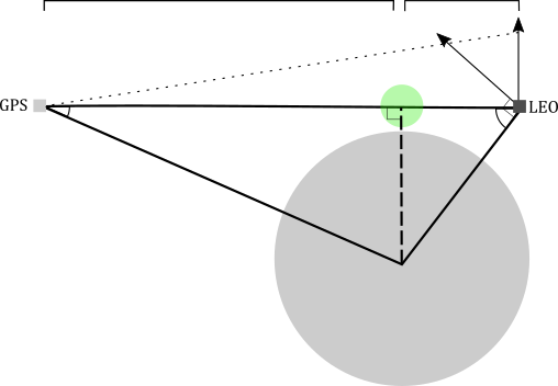
Radio Occultations (RO)
Overhead Obs.
LEO Occultations
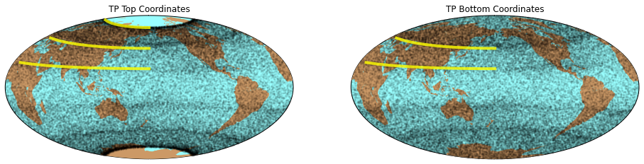
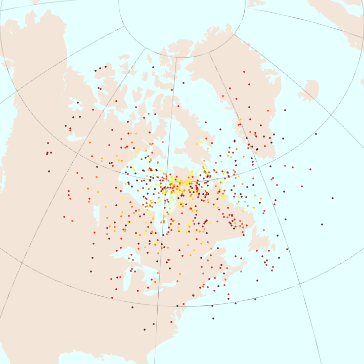
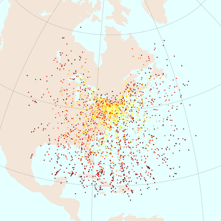
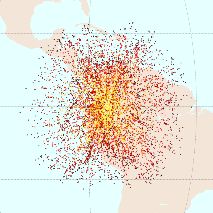
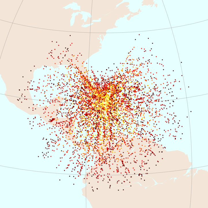
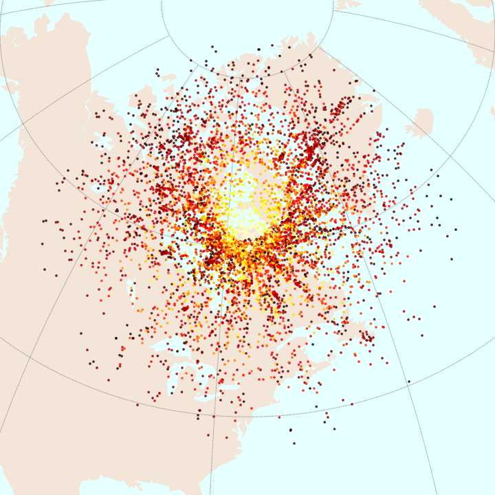
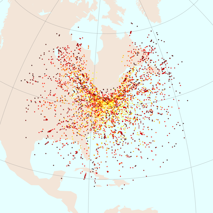
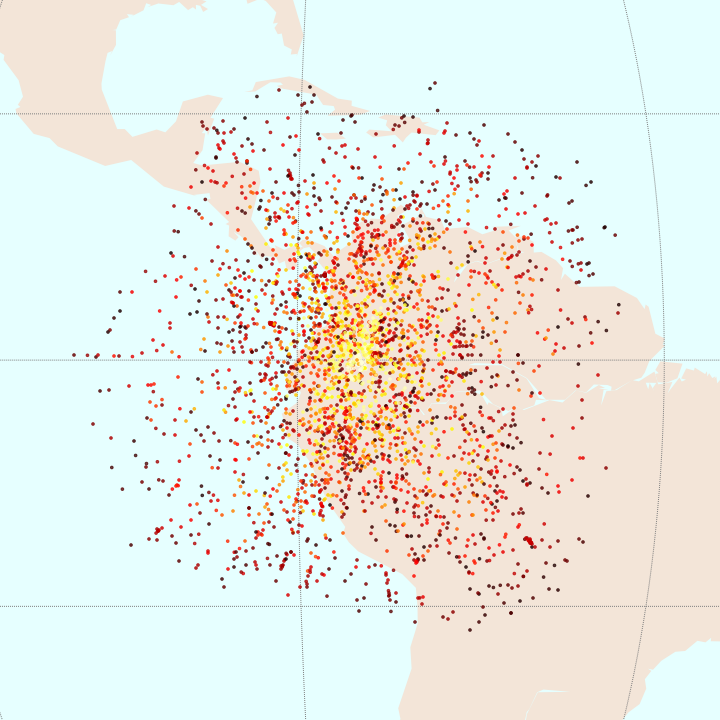
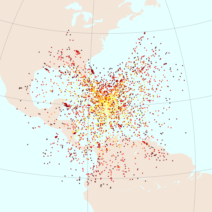
90-day scatter of COSMIC-GPS occultation tangent points
top coords.
bottom coords.
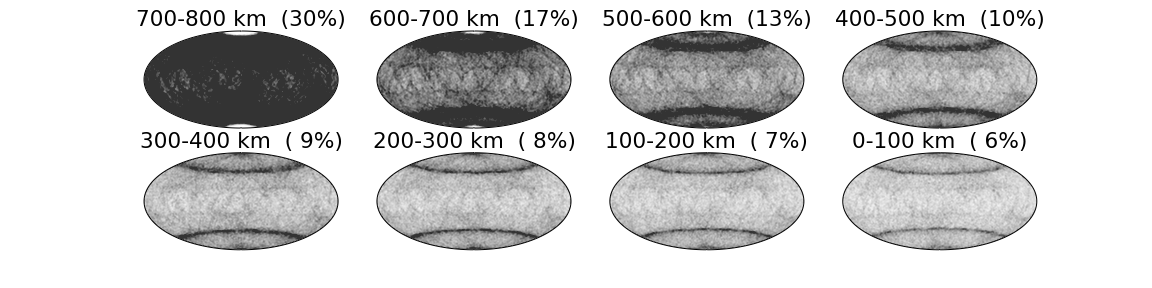
tangent point altitude histogram
LEO Occultations
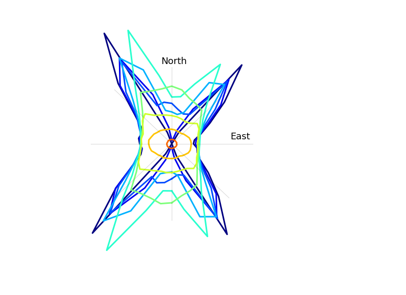
90-day histogram of COSMIC-GPS occultation tangent point azimuths
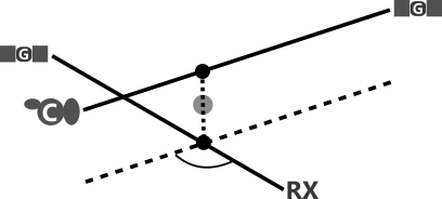
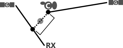
Geometry
common observation volume
RO tangent point
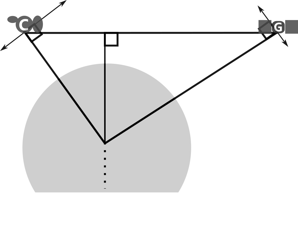
Ground/LEO Common Volume
3D Line-Segment Intersection
-
common-volume point-of-interest
- midpoint b/w points of closest approach
- GNSS rays <100 km apart
"the points of closest approach between two line segments"
*must handle special case where point of closest approch is on segment endpoint.
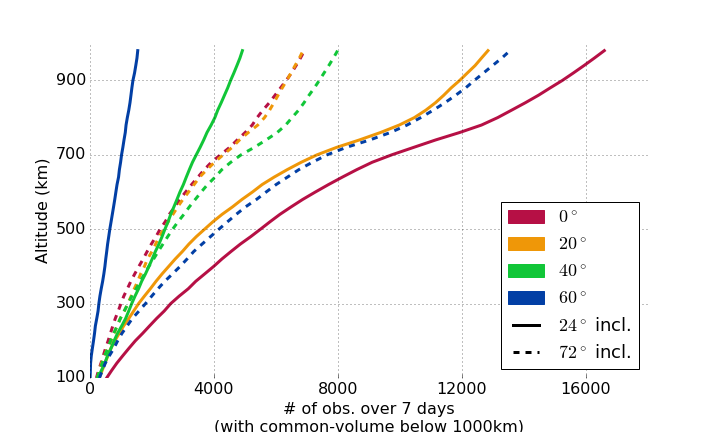
Ground/LEO Common Volume
Ground/LEO Common Volume
60°
40°
20°
0°
-
6-satellite constellation
-
750 km altitude
-
24° inclination
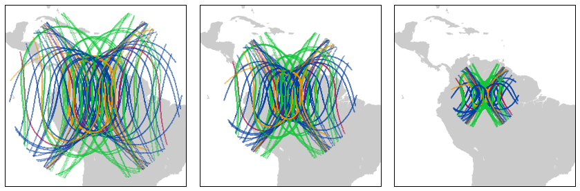
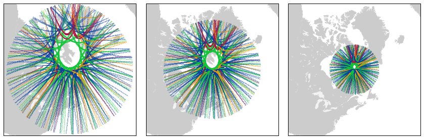
Ground/LEO Common Volume
60°
40°
20°
0°
-
6-satellite constellation
-
750 km altitude
-
72° inclination
Ground/LEO Common Volume
-
6-satellite constellation
-
750 km altitude
-
24° and 72° inclination
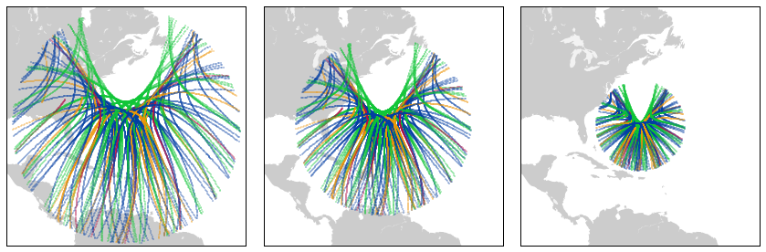
LEO Beacon Observations
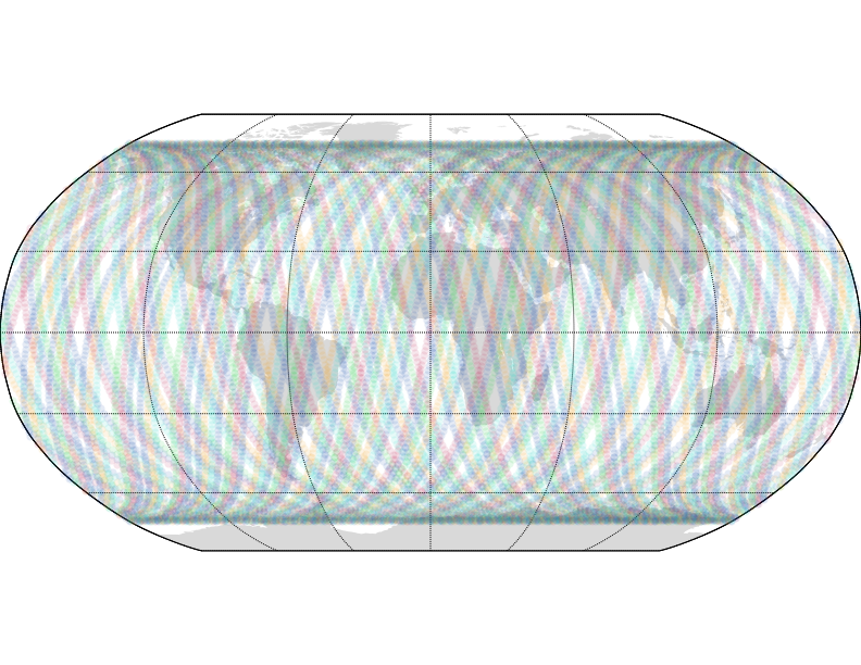
LEO constellation ground track coverage
72° incl.
LEO beacon IPP
@ 150 km and 20° elev.
if we had beacon RX at every IGS station
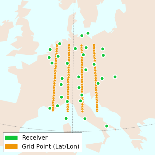
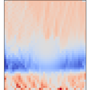
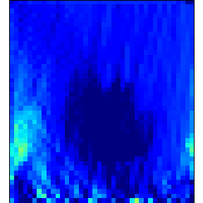
Simulated Effects on Localized Imaging
- regional IGS network in Europe
- latitudes
- 43°-53° @ 0.25° sep.
- longitudes
- 6°-15° @ 3° sep.
- altitudes
- 100-980 km @ 20 km
- attempt to reconstruct IRI image with depletion feature from uniform density starting image
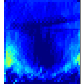
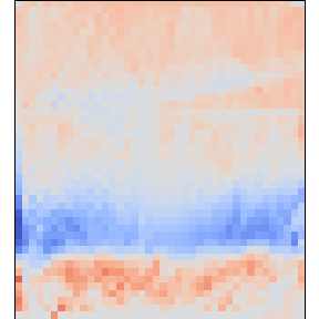
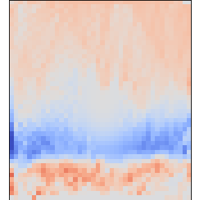
Simulated Effects on Localized Imaging
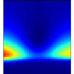
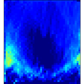
ground
LEO RO/overhead
ground
LEO beacon
LEO RO/overhead
ground
100 km
1000 km
53°
43°
no regularization used in order to emphasize affects of different data
Future Work
- Low elevation ground GNSS esspecially important at low altitude
- use 3-frequency GNSS measurements to address low-elevation TEC estimation
20° el. mask
5° el. mask
Conclusions
- Poleward deficit of GNSS satellites causes gap in information from ground receivers
- Occurrence of ground and LEO GNSS observations in common volume heavily depends upon LEO constellation orbital inclination
- Overhead and RO LEO observations aid in topside ionosphere imaging
- LEO beacons have good potential to improve 3D imaging over ground and LEO GNSS observations
- Accurate low-elevation GNSS measurements will allow improved imaging
Acknowledgements
This research was supported by the Air Force Research Laboratory and NASA.
References
- TS Kelso et al. Validation of sgp4 and is-gps-200d against gps precision ephemerides. 2007
-
"COSMIC-2." COSMIC 2. UCAR, n.d. http://www.cosmic.ucar.edu/cosmic2. 02 Jan. 2016.
-
Yue, Xinan, et al. "Observing system simulation experiment study on imaging the ionosphere by assimilating observations from ground GNSS, LEO-based radio occultation and ocean reflection, and cross link." IEEE Transactions on Geoscience and Remote Sensing 52.7 (2014): 3759-3773.
-
Yue, Xinan, et al. "Global 3‐D ionospheric electron density reanalysis based on multisource data assimilation." Journal of Geophysical Research: Space Physics 117.A9 (2012).

COSMIC (LEO-based)
horizontal TP speed proportional to
vertical TP speed proportional to
||v_{SV}||
||v_{SV}||\cos\theta_{SV}
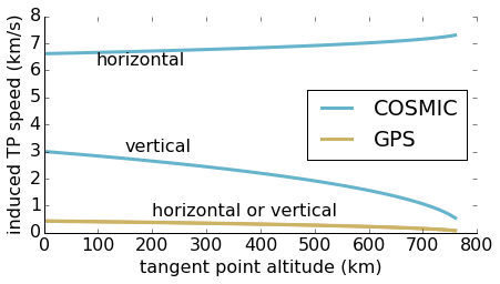
images originally published at www.cosmic.ucar.edu
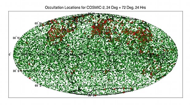
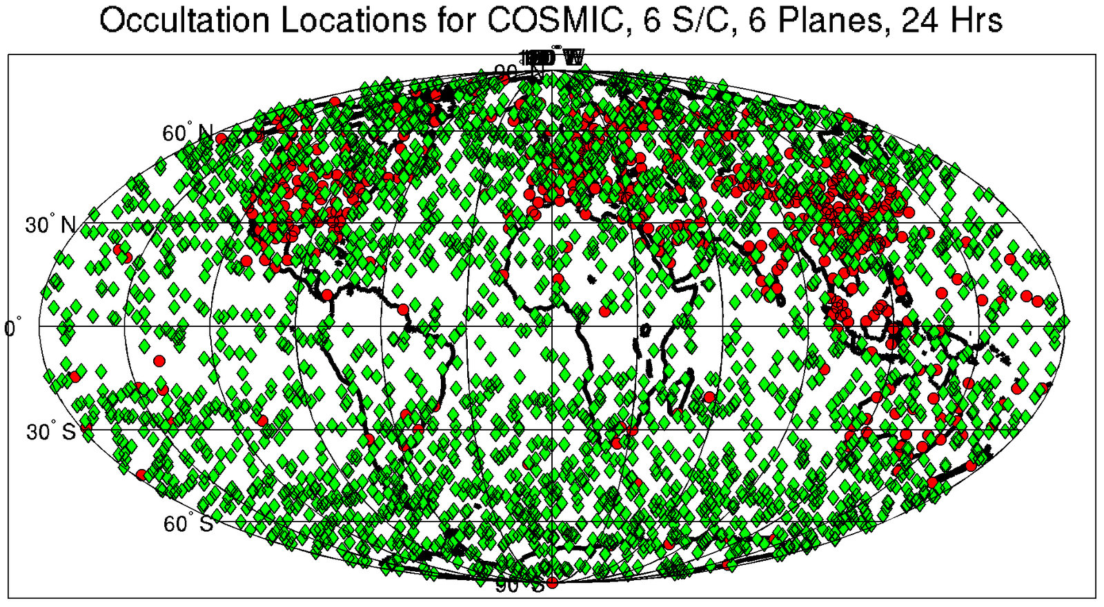
Occultation occurrences over 24 hours for COSMIC and COSMIC-2
COSMIC 2
Mask/Filters
- GPS 1 (for RX) elevation > threshold (5 degrees)
- closest approach of LEO ray-path to Earth surface > 2 km altitude
Ray paths through Earth
- proximity < threshold (100 km)
- common-volume altitude < threshold (1500 km)
Volumes way out in space
Ionosphere Observability by Ground and LEO GNSS Receivers
By Brian Breitsch


