Virtual Cafe
3D Object Recognition By Using Google Tango Project And Creating Virtual World
Members
Virtual Cafe


Wan
Chatchawan Yoojuie
Benz
Natthakul Boonmee
Top
Kanin Kunapermsiri
Virtual Cafe
3D Object Recognition By Using Google Tango Project And Creating Virtual World
Advisor
Dr. Kwankamol Nongpong
Senior Project
Semester 2/2016
Introduction

1
What Tango can do
-
Create indoor navigator (without using GPS)
-
Create accurate measurement tools
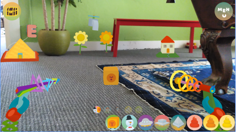
-
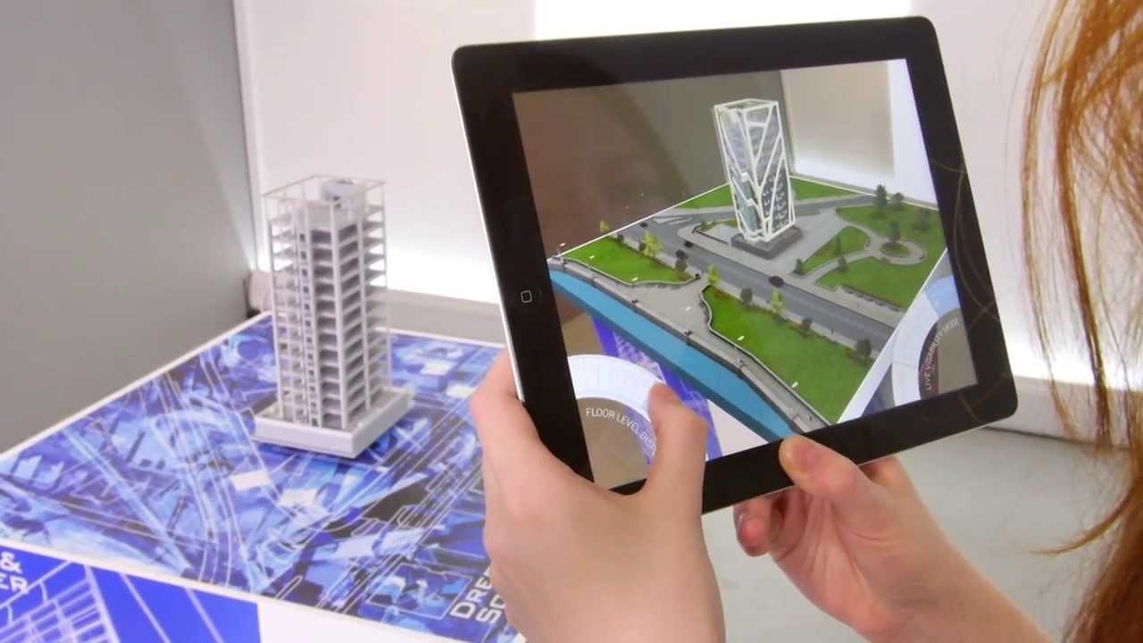
Create augmented reality game
Tango
2
What Tango cannot do
-
3D object detection
-
Create realistic augmented reality application
Tango
3
Goal of Project
- Learn the surrounding environments and transform the physical world into the virtual world

- Recognize the 3D object and display inside the virtual world

- Basic interaction with the objects inside the virtual world

Note: The environments and detected object will be unmovable.
Goal
4
Software
-
Google Platform

- Point Cloud Library
- Unity
for capturing image and position
for 3D image processing
for rendering virtual world and virtual object
Tools
5
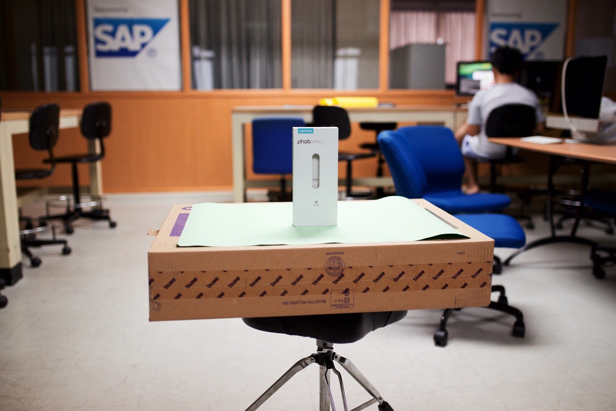
Hardware
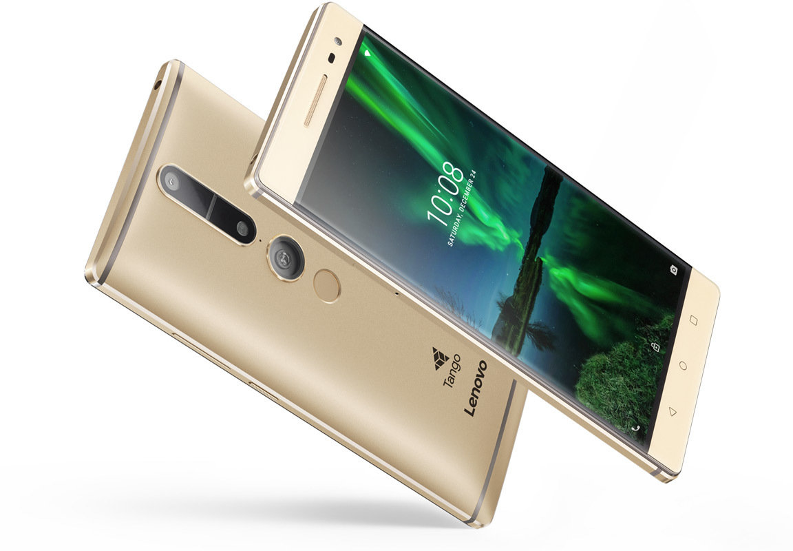
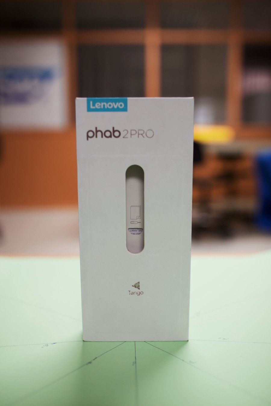
- Lenovo Phab 2 Pro
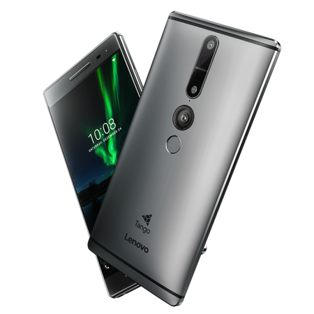
Supported by Google Tango
Tools
6
Google Tango Platform
- It’s a computer vision platform that can do the Area Learning, Motion Tracking, and Depth Perception
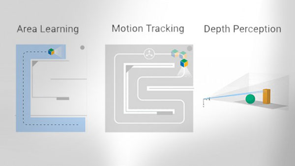
7
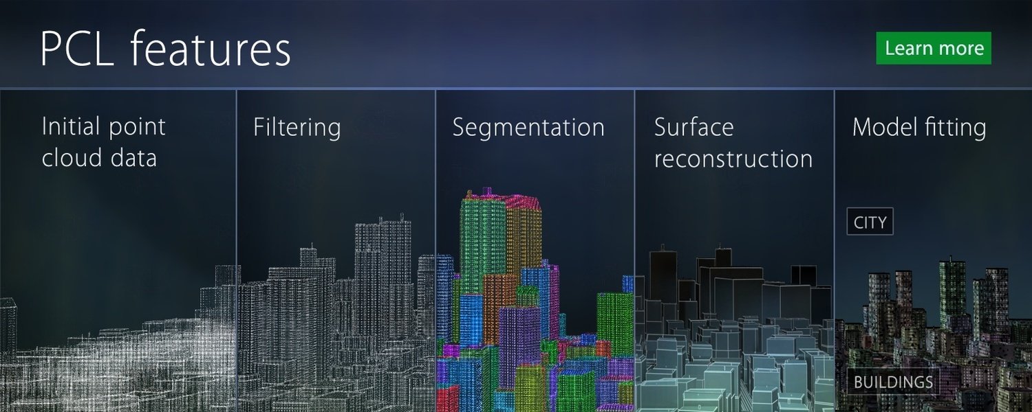
Tools
- Computer vision library for 3D image which is used for processing the data and recognizing objects using C++
8
Point Cloud Library
Tools
9
Tools
10
Tools
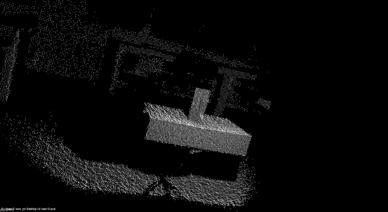
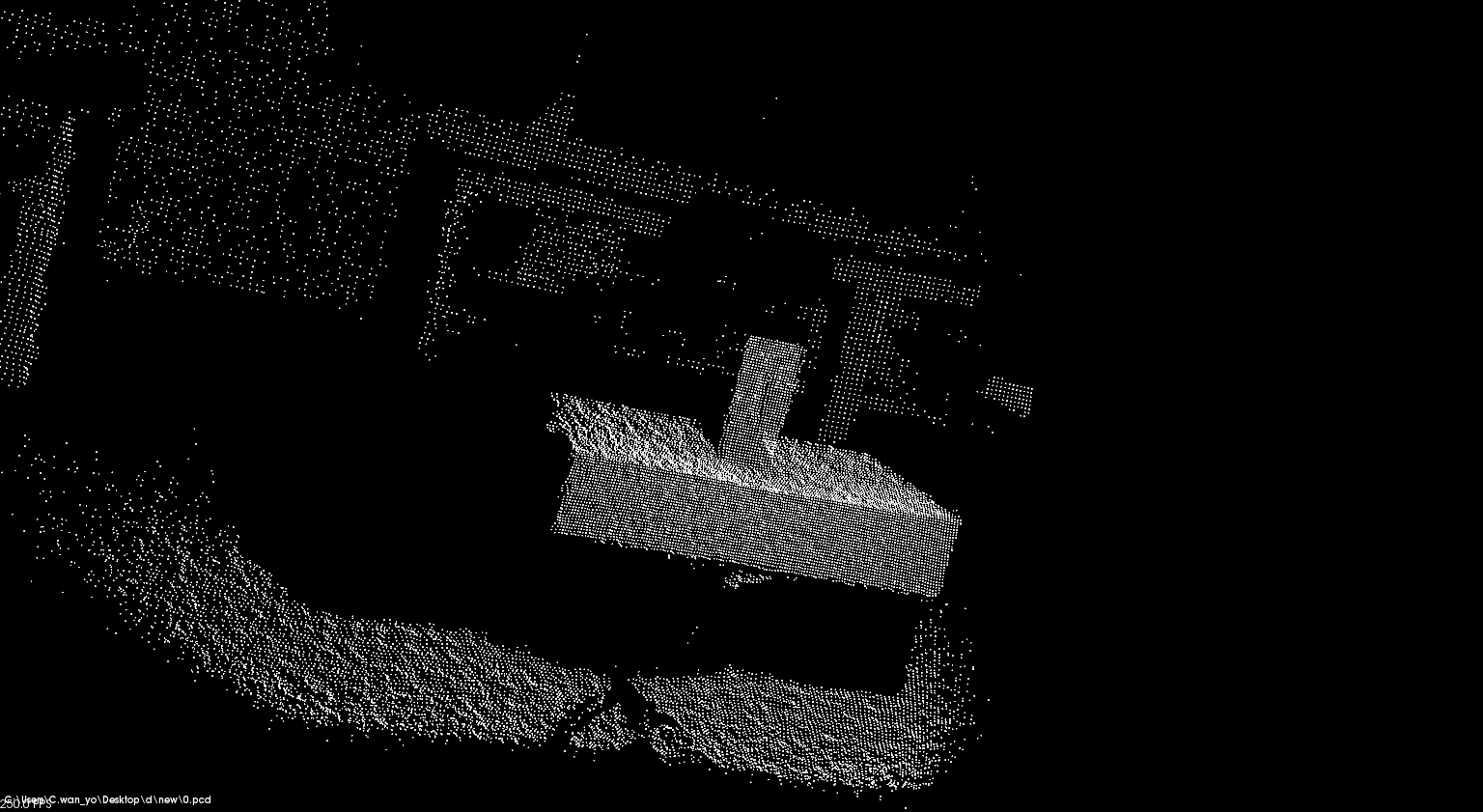
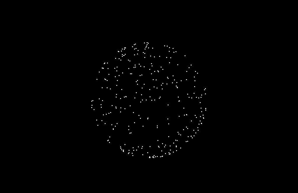
Point Clouds
Point cloud is a set of points in the 3D coordinates system
It represents as 3D image and each point in the image contain x, y and z value
-
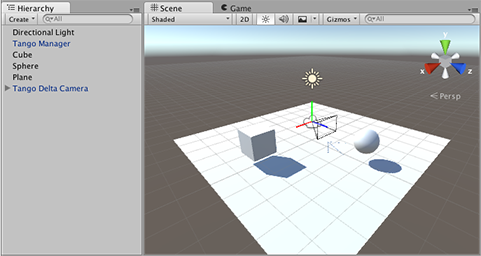
The game engine which provides all necessary tools
-
Coding in C#
-
Use for rendering 3D objects and virtual world
- Google provided Tango API for unity
11
Unity
Tools
-
Android phone that supports Google Tango Platform
-
Equipped with IR sensor for capturing point cloud
12
Tools
Lenovo Phab 2 Pro

13
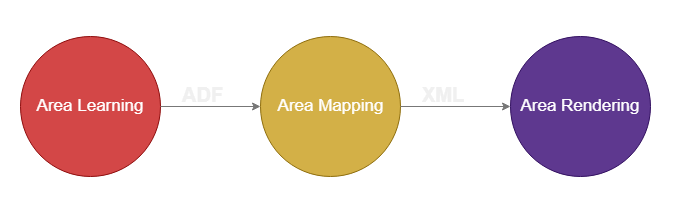
Framework
Framework

1. Area Mapping (Creating a room)
The design framework can be divided into two parts :-

2. Training Dataset and Object Recognition
14
Framework
Area Learning
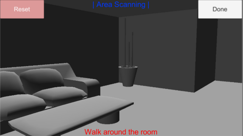
-
Make application remember the room by scanning around the room
-
Save into ADF file

15
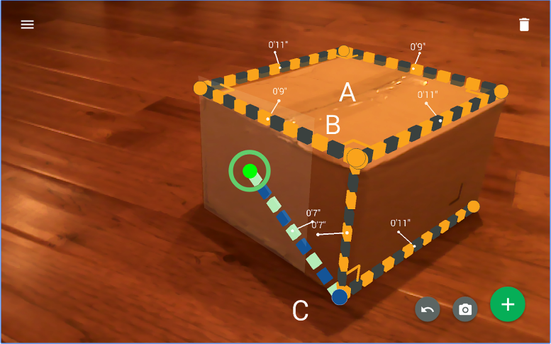
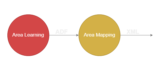
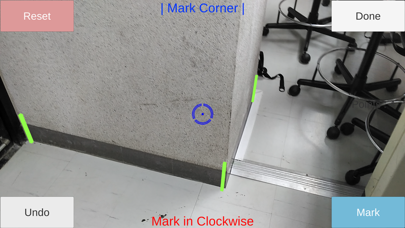
Framework
Area Mapping
-
Measure the actual room size by marking corners and look for distance
-
Save into XML file
16
Framework
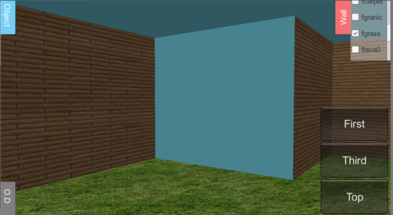
Area Rendering
-
Load the ADF file that we saved in area learning part along with the XML file that contains all the vertices representing the corners of the room
-
Use Unity to render previous data
into virtual room
17
Framework
1. Area Mapping (Creating a room)
The design framework can be divided into two parts :-
2. Training Dataset and Object Recognition
Framework
18
Framework
Training Dataset
-
Create datasets that will be used in matching step
-
Recognize the object with the dataset
-
6DOF pose estimation of the detected object
-
Display object model in Unity
The centroid is a point of the result by calculating the mean value of all points in the cloud
19
What is Centroid?
It is a " Center of Mass "
Framework
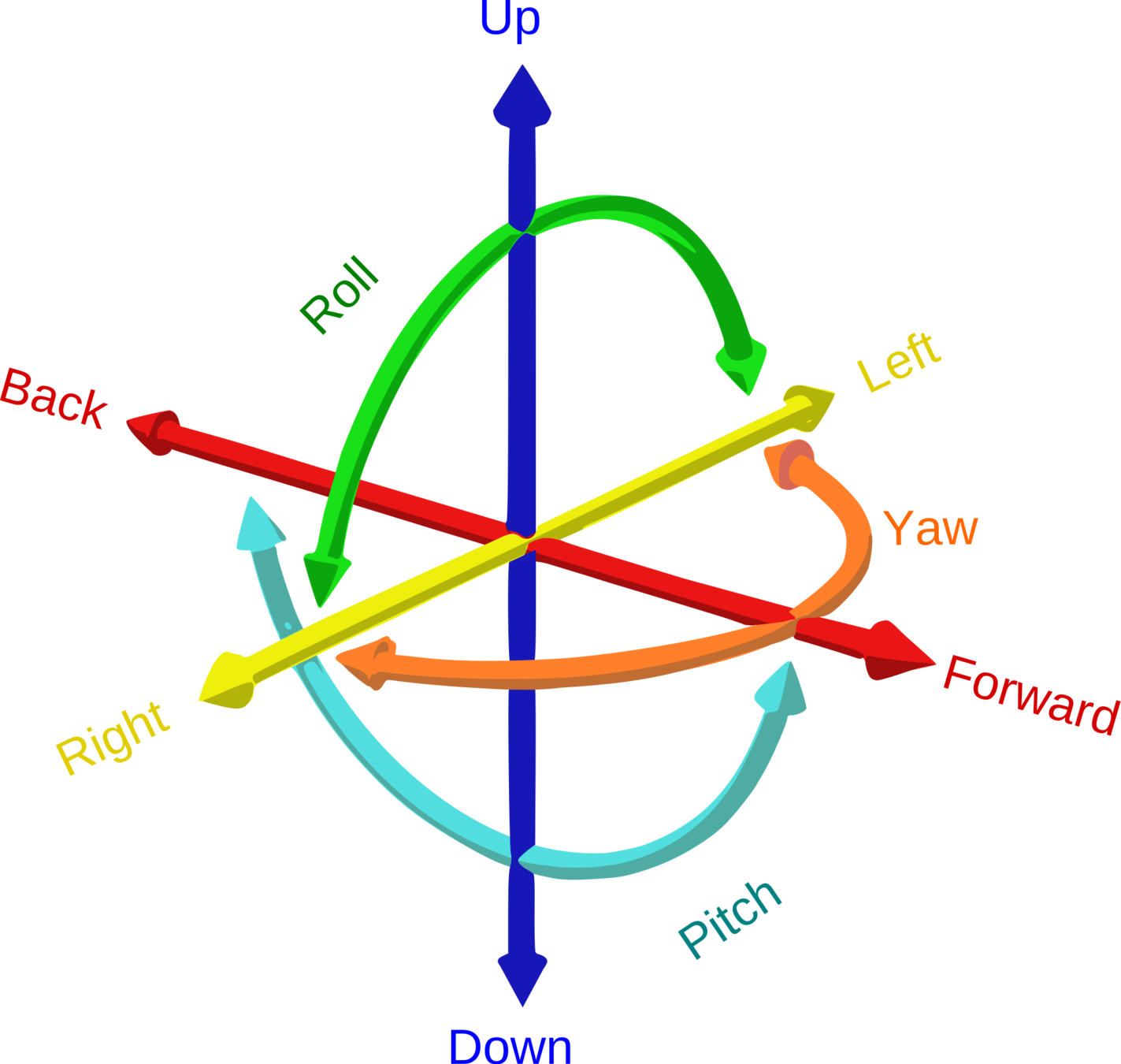
Six degrees of freedom (6DoF) refers to the position of the object in 3D dimension space which is described with translation and rotation
20
What is 6DoF?
Framework
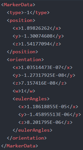
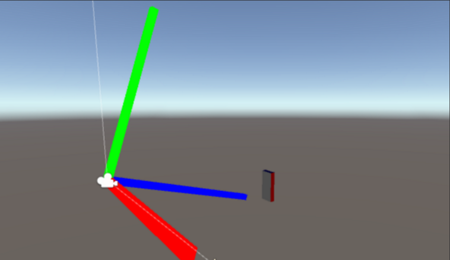
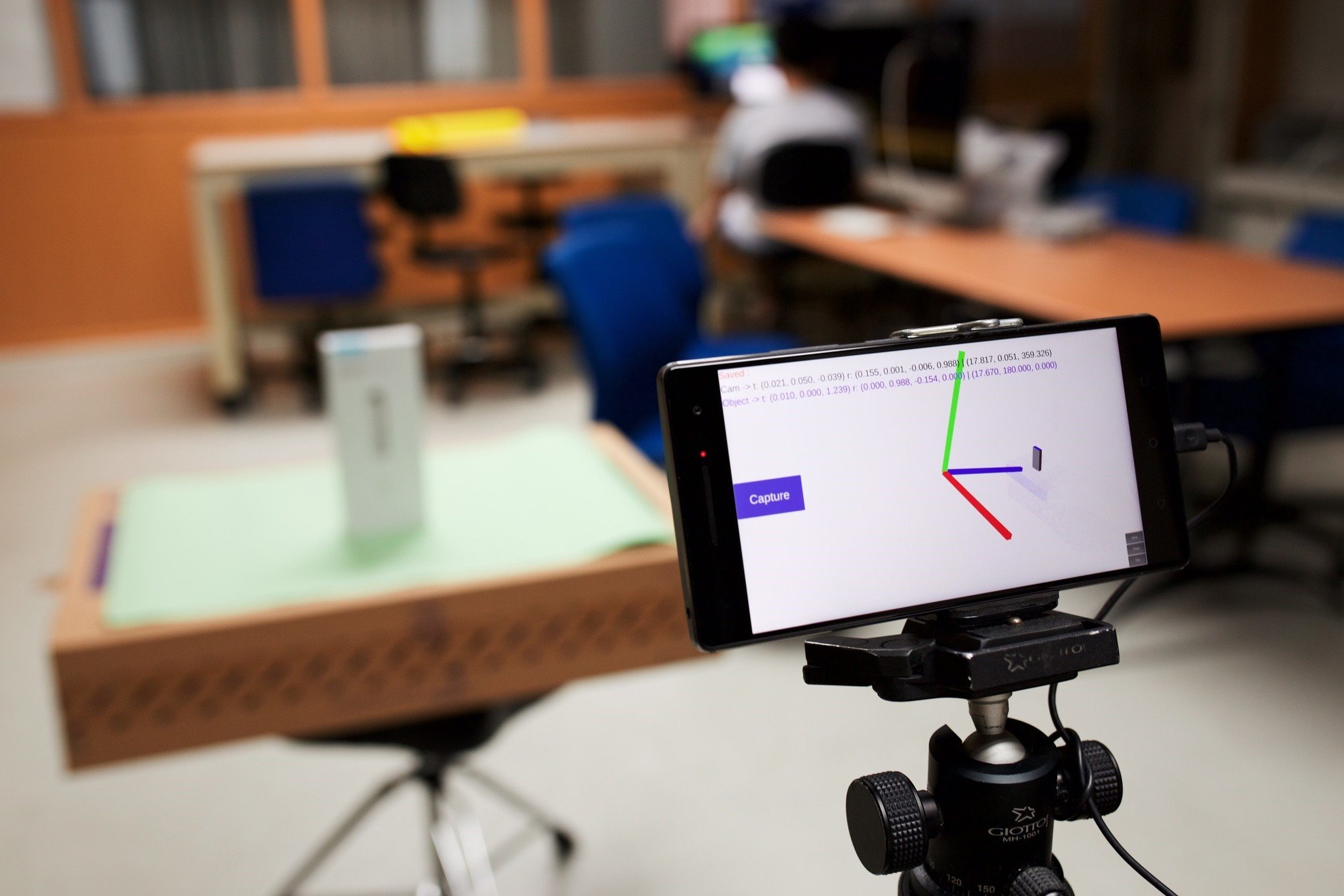
With ground-truth information of the object in unity coordinate system
It contains these information :-
1. Translation of the device (Vector format)
2. Rotation of the device (Quaternion format)
3. Translation of the object (Vector format)
4. Rotation of the object (Quaternion format)
21
How can we find 6DoF of the object?
Framework
0    0    0
-0.259    0.001    -0.004    -0.966
-0.027    -0.082    0.0754
0    0.966    -0.259    0
Feature extraction that encodes the information about the point cloud
Basically, there are two types of descriptor in PCL :-
1. Local - computed for individual points
2. Global - computed for the whole cluster that represents an object
22
What is descriptor?
Framework
VFH (Viewpoint Feature Histogram)
23
Framework
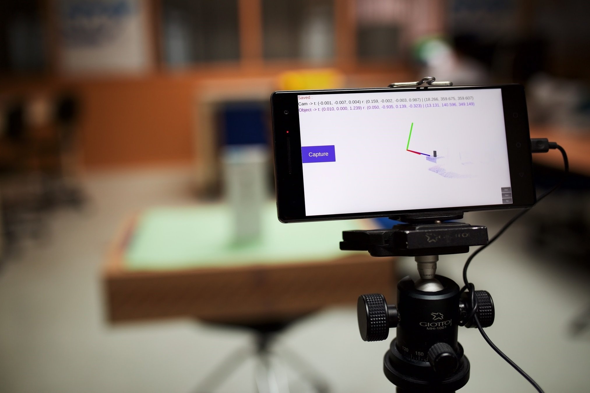
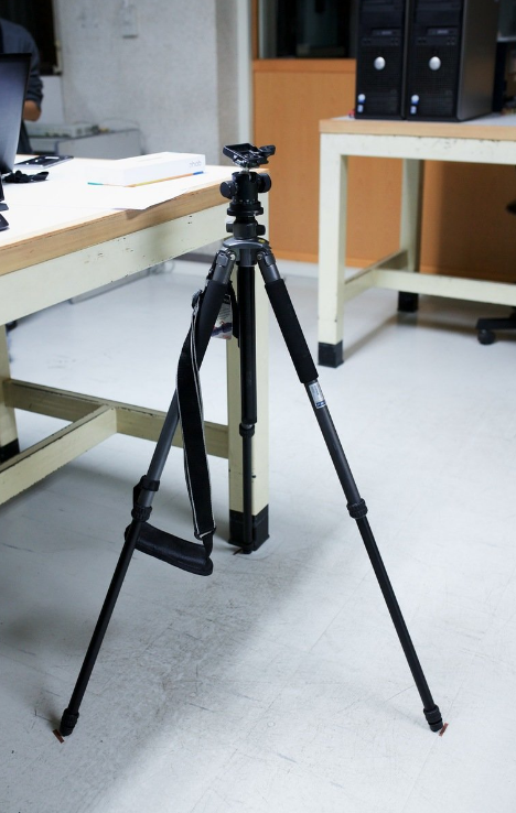
Setting Up
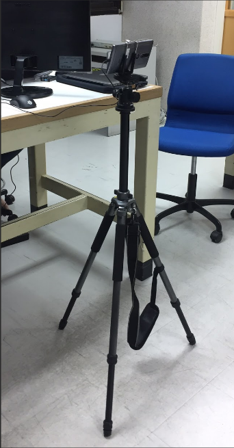
Tripod
Pan-tile

24
Framework
Collecting Dataset
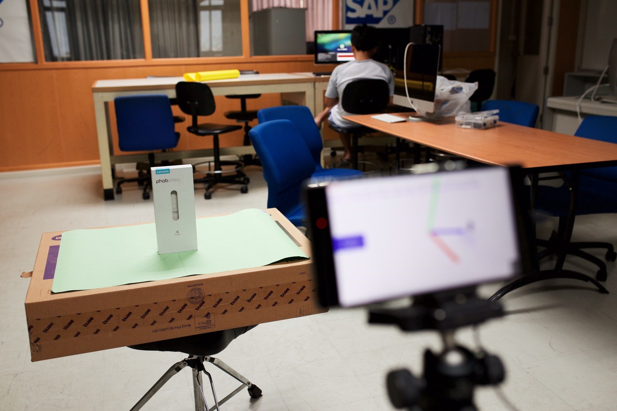
- Capture the snapshots of the object along with ground-truth (pose) information of the object at every 40 degree
- As a result, we have a total of 9 different snapshots
- Then, we use these 9 snapshots as reference frames
25
Framework
Collecting Dataset
- We can improve and extend the dataset using these reference frame
- Also, the descriptors must be computed for every snapshot in the dataset
Structure of the dataset :-
1. Object Snapshot ( .PCD )
2. Descriptor ( .PCD )
3. Ground-Truth ( .TXT )
26
Framework
The design framework can be divided into two parts :-
Framework
2. Training Dataset and Object Recognition
27
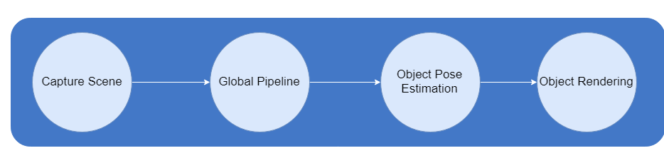
Framework
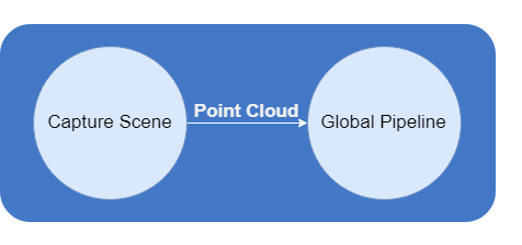
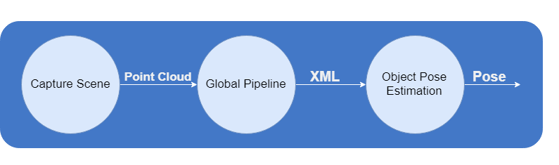
Capturing Scene
-
Capture point cloud and send to the server via socket
-
Then, follow the process of Global Pipeline

28
Framework
Global Pipeline
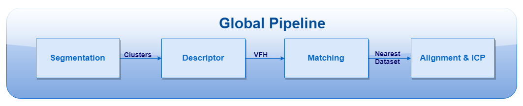
The global pipeline contains 4 steps
29
Framework
Segmentation
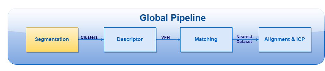
Perform segmentation on the cloud in order to retrieve all possible clusters on the plane surface

30
Framework
Descriptor
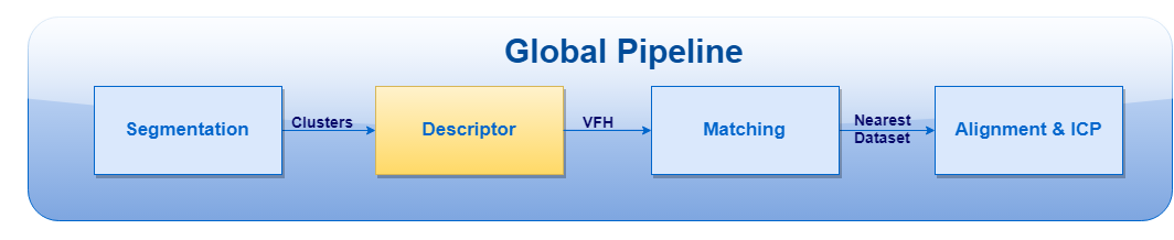
For every cluster that has survived in the segmentation step, a global descriptor must be computed
31
Framework
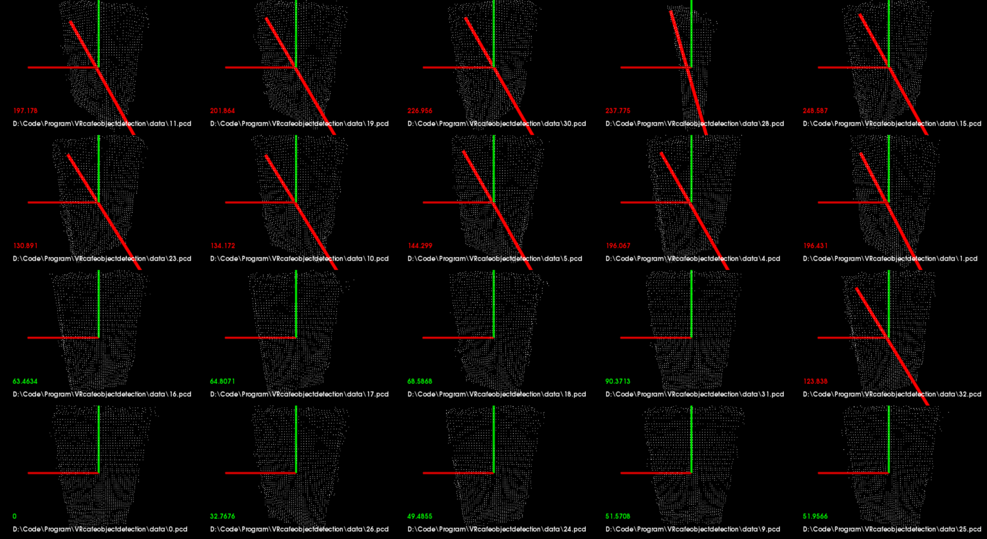
Matching
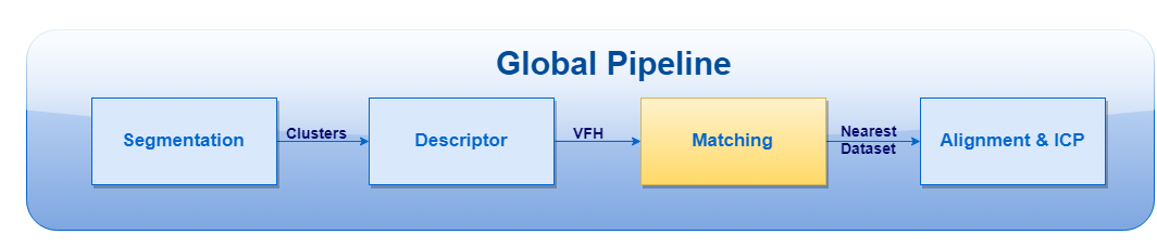
Use the descriptor to perform a search for their nearest neighbors in the database
32
Framework
Alignment & ICP
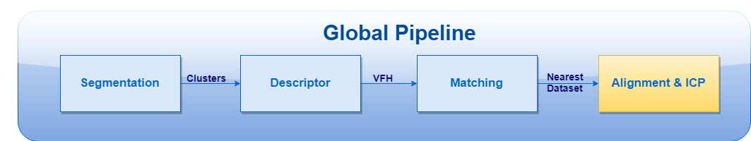
- With ground-truth that saved along with the dataset
- Determine translation of object by computing and aligning the centroids of the clusters
- For the rotation, we can use ICP to compute and find the best transformation from source (given dataset from matching step) to target (current cluster)
33
Framework
Alignment & ICP
34
Framework
Object Pose Estimation
-
The output of the global pipeline will be sent back to the device
-
Output is in XML format
-
Some calculation needed to extract those pose estimation of the object and display in Unity
35
Framework
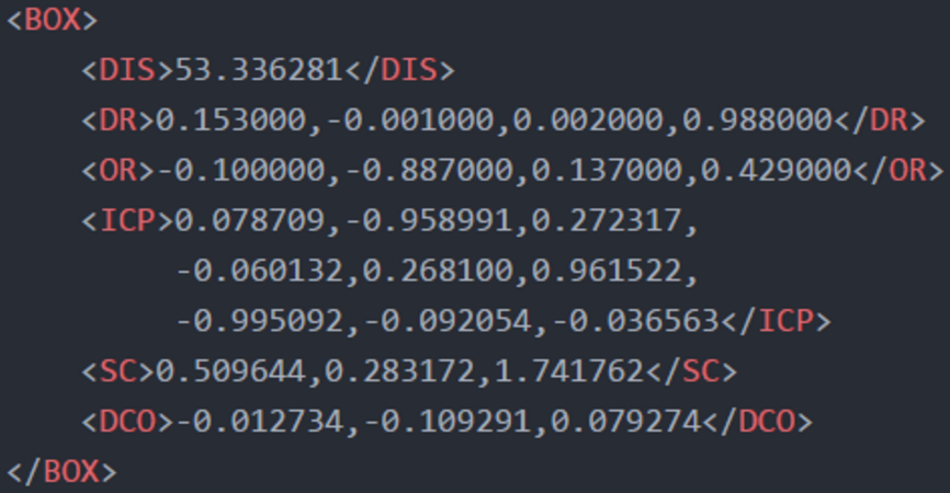
Object Pose Estimation
These are 5 pieces of information extracted from the output:
(1) DR = Unity ground-truth of D : device rotation in Quaternion format
(2) OR = Unity ground-truth of D : object rotation in Quaternion format
(3) ICP = ICP from S to D : transformation in Matrix format
(4) SC = Centroid of S in Vector format
(5) DCO = Database centroid offset, the offset of the centroid between SC(4) and Unity ground-truth of D : object centroid(6) in Vector format
1
2
3
D
S
4
6
D
Unity Coordinate
PCL Coordinate
36
Framework
Use Unity to render the detected object according to the data that extracted from previous
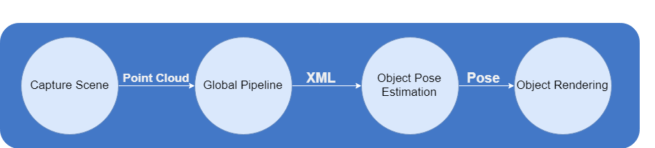
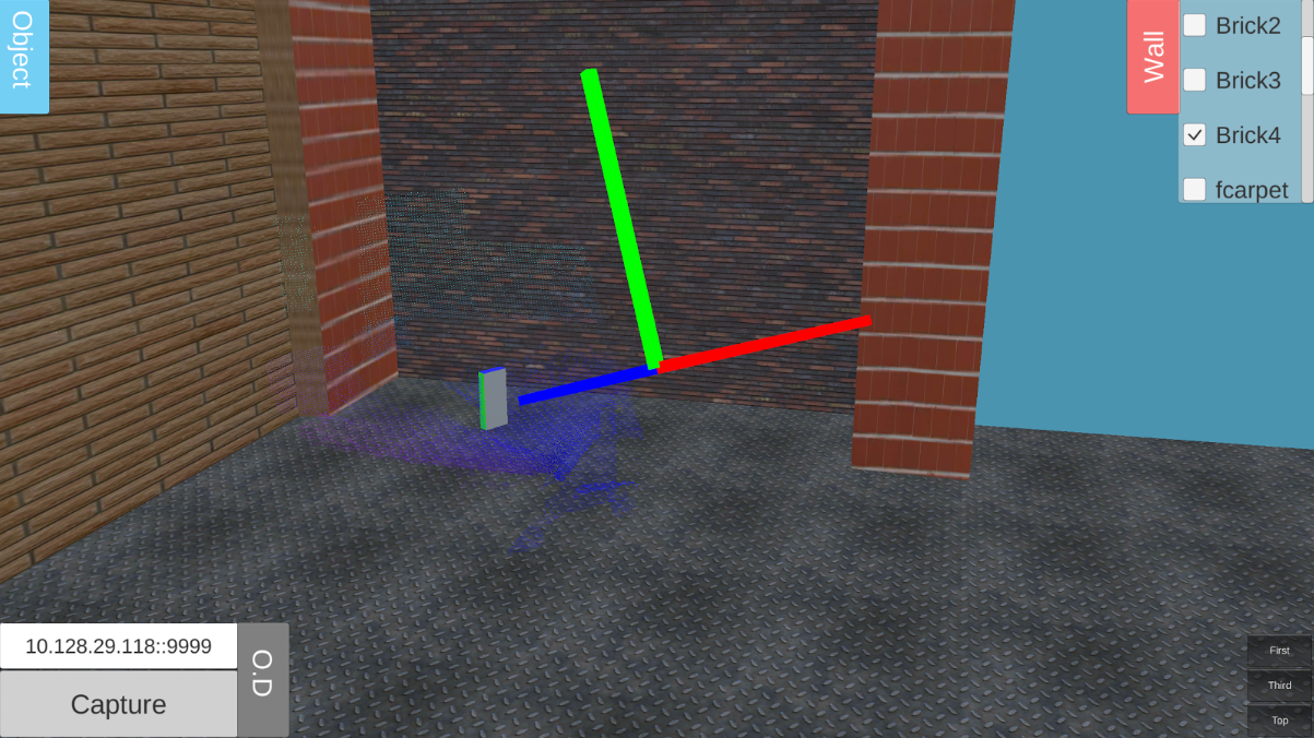
Object Rendering
37
Flow
Flow of The Application

38
Evaluation
Evaluation
- Testing for precision, recall, and f-measure of object recognition
-
Testing for how well it can get the correct pose
-
Use a single white rectangle box for both testing
39
Preparing Dataset
Training dataset :
- There are 2 datasets which object is trained
- First dataset has 34 scenes, trained at range 0.9 metre
- Second dataset has 16 scenes, trained at range 1.5 metre
Evaluation
40
Preparing Dataset
Testing dataset :
- Use 3 sets which object will be placed at range 0.5, 1.0, and 1.5 metre
- Each distance has 10 scenes that will contain the object at different viewpoint (rotate at every 40 degrees)
- Addition 5 more scenes without the object
Evaluation
41
Preparing Dataset
Total of tested scenes :
- With Object = 30 scenes
- Without Object = 15 scenes
Evaluation
42
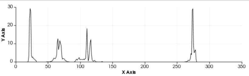
Sample Point Clouds
Captured At Training
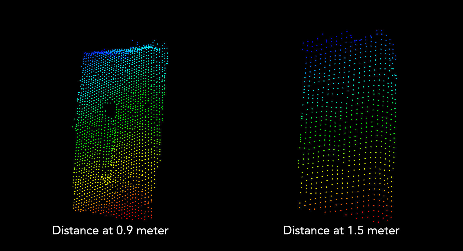
Evaluation
43
Environment
- Room with no sunlight passing through
- No mirror
- Use tripod to hold the device steady
Evaluation
44
Result - Detection Accuracy
Dataset 1 At 0.9 metre
Dataset 2 At 1.5 metre
-
The performance from dataset 2 is significantly drops compared to dataset 1
-
The threshold value of the matching is too large
-
The quality and detail of the point cloud changed according to distance
Evaluation


45
Result - Pose Estimation
-
Distance of the object at the training stage have a huge impact on the accuracy of the recognition system
-
At 0.5 metre is slight lower performance than at 1.0 metre.

DEMO
46
Challenges
Challenges
- Limited access to Tango API
- Difficult to control variable
- The sensor is poor, so the distance can affect the details of the point cloud
- Compile Point Cloud Library for android
- Small community
- Less example
- Less guideline
47
Imporvement
Improvement
- Training dataset can be improved by using pan-tilt that can be rotated almost at all the angles i.e., x, y and z rotation
- Do some research on how to improve the quality of the point cloud
- Q&A -
Thank you
VIRTUAL CAFE
By Cwan Yo