DC-Circuits
The flow of electric charges
DC-circuits
The flow of charges
The main characters
\Delta V
V
I
R
DC-circuits
The flow of charges
The main characters
\Delta V
Z
X
R
Current
I
R
The Electric Potential (or to be more precise, the Electric Potential Difference, aka Voltage)
This quantity is related to the change in energy per unit charge as it flows from one point to another. Either in terms of energy boost, or energy loss.
The (conventional) Electric Current --
Defined as the rate of charge flow in a conductor.
The Electric Resistance --
This is a physical quantity that represents the attenuation of energy in a device (electric energy converted to some other form of energy like heat or light etc.)
The underlying physics
DC-Circuits
The flow of electric charges
DC-circuits
The flow of charges
Ingredients
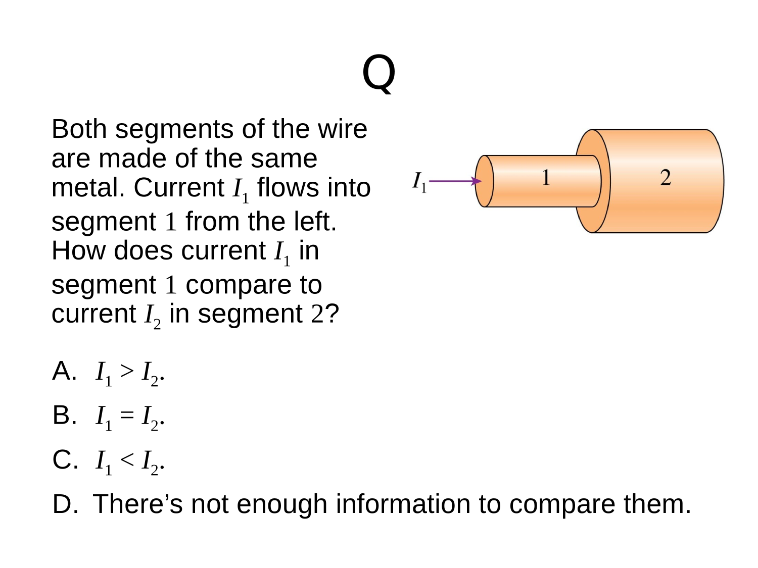
First, you need a conductor as a conduit for electricity
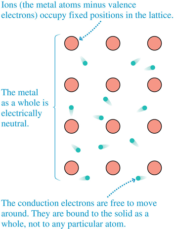
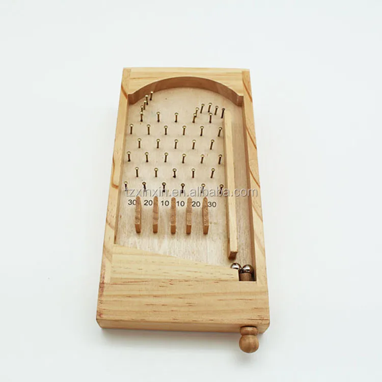
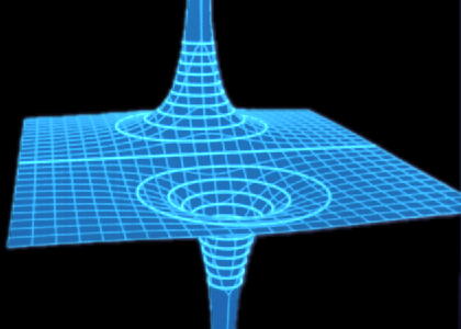
The positively charged ions in the metal are ~fixed in a lattice & the (many many) conduction-electrons bounce around like pinballs in the potential landscape.
DC-circuits
The flow of charges
Ingredients
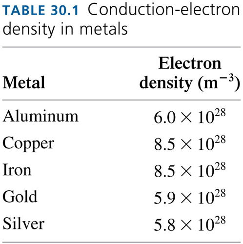
Q: What is the average speed of an electron within the metal?
A: Assuming a simple model of a 3D electron gas @ room temp:
\frac{1}{2}m_e v^2=\frac{3}{2}k_B T
v=\sqrt{\frac{3k_B T}{m_e}}\approx 10^5 \: m/s
\text{Kinetic Energy} = \text{Thermal Energy}
DC-circuits
The flow of charges
Ingredients
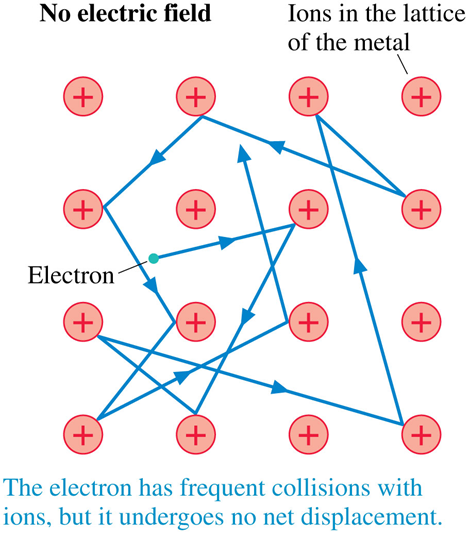
In the absence of an electric field, the kinetic energy of the conduction electrons is due to the ambient thermal energy
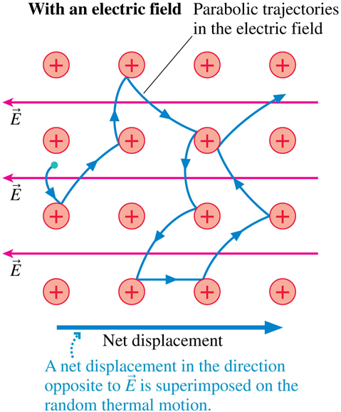
Q: Why are the trajectories parabolic?
A: Projectile motion
\implies \vec{a} = \frac{q_e}{m_e} \vec{E}
\implies q_e \vec{E} = m_e \vec{a}
\Delta\vec{r} = \vec{v}_0 t + \tfrac{1}{2}\vec{a}t^2
an electron experiences constant acceleration in direction opposite of field,
and constant velocity perpendicular to field.
\vec{F} = m \vec{a}
DC-circuits
The flow of charges
Ingredients
Establishing an electric field within the conductor causes the conduction electrons to flow.
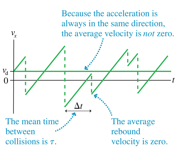
Q: What is the average "drift" velocity?
typically, very slow ~
~ 10^{-4} m/s
{v}_{d} = a\ t
\implies v_d = \frac{q_e \tau}{m_e} E
If the average time between collisions is
DC-circuits
The flow of charges
Ingredients
\tau
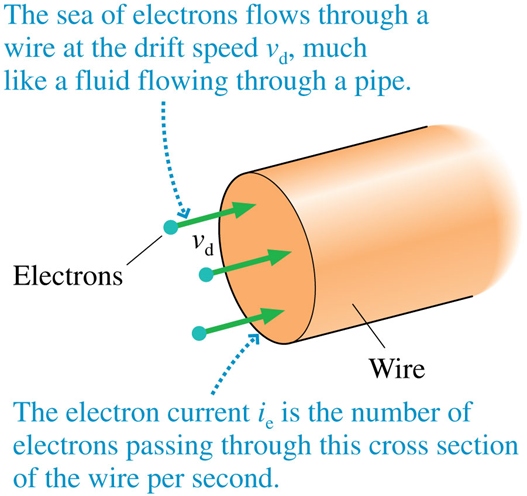
Then, you make a wire
DC-circuits
The flow of charges
Ingredients
DC-circuits
The Electron Current
Definition
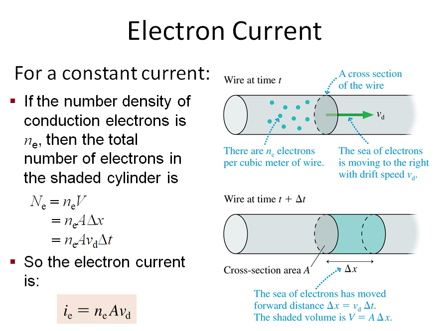
\implies i_e= \frac{n_e\ A\ q_e\ \tau}{m_e} E
DC-circuits
The flow of charges
Ingredients
First, you need a conductor
as a conduit for electricity
as a conduit for electricity
as a conduit for electricity
as a conduit for electricity
as a conduit for electricity
The Electric Current
DC-Circuits
The flow of electric charges
DC-circuits
The flow of charges
The _Conventional_ Electric Current

Conventional current can be visualized as traffic or water flow
Conventional current always flows from high potential to low potential
The SI unit for conventional current is the Ampere
A = \frac{C}{s}
The Electric Current
The rate of charge flow in a conductor
I = \frac{dQ}{dt}
is defined as ...
DC-circuits
The flow of charges
The _Conventional_ Electric Current
The SI unit for conventional current is the Ampere
A = \frac{C}{s}
The Electric Current
The rate of charge flow in a conductor
I = \frac{dQ}{dt}
is defined as ...
The DC Source
DC-Circuits
The flow of electric charges
DC-circuits
The flow of charges
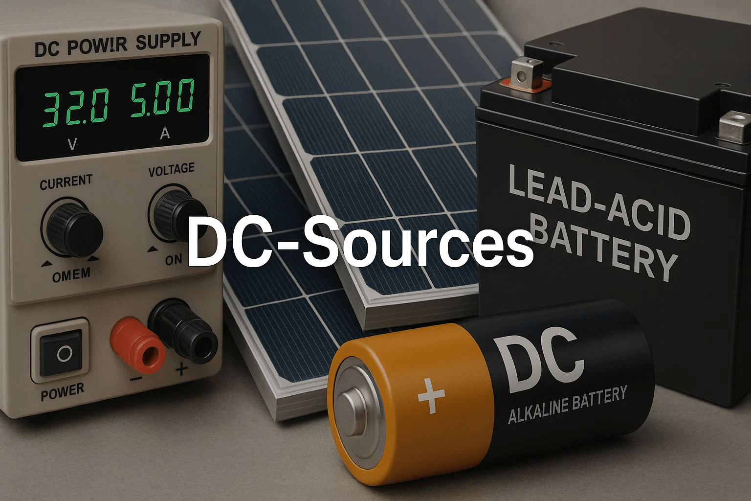
DC source
Electromotive Force (EMF)
A Direct-Current (DC) source* can be modeled as a two-terminal device that keeps one terminal (labeled +) at a fixed higher electric potential than the second terminal (labeled -)
*aka a source of Electromotive Force (EMF) ... a term that does not actually quantify a force, but rather a driving voltage (Electric Potential Difference.)
\mathcal E
+
-
The icon representing a DC source in a circuit. The long stick indicates the terminal at a higher potential.
DC-circuits
The flow of charges
DC source
+
-
e^-

When a DC source is connected across an external electric load, the conduction electrons flow from the "negative" terminal through the load to reach the "positive" terminal.
Electrons "lose energy" as they go through the electric load; the electric potential energy gets converted into some other form. e.g. light or heat.
A battery is a source of EMF, providing the electrons with energy through chemical means.
DC-circuits
The flow of charges
Boosting electrons with multiple sources
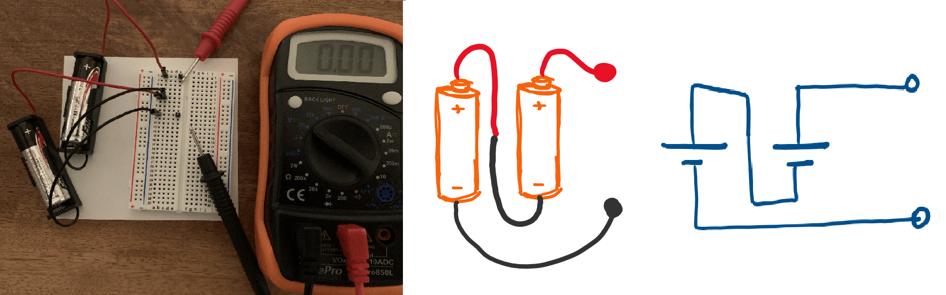
Sources connected in series boost the energy of the electrons sequentially resulting in an overall higher energy boost per electron.
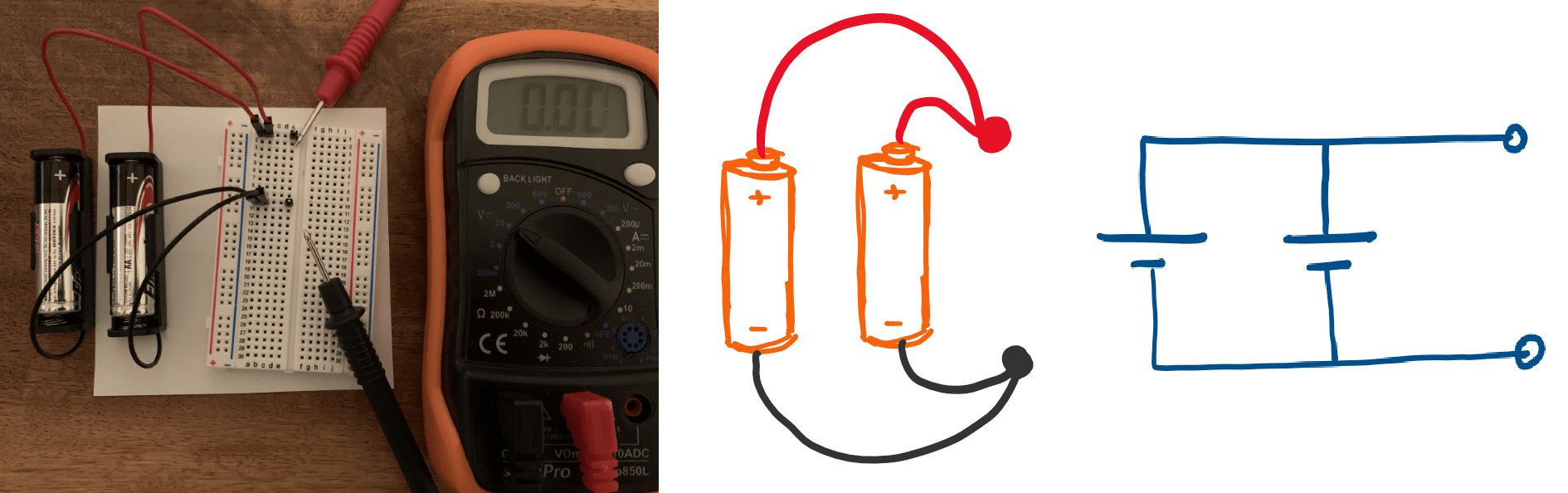
Sources connected in parallel boost the energy of the electrons in tandem resulting in an overall higher rate of supply of electrons.
DC-circuits
The flow of charges
Boosting electrons with multiple sources
Watch this video for an interesting visualization of the electric potential in a circuit with one or many DC sources.
Electric Resistance
DC-Circuits
The flow of electric charges

DC-circuits
The Electric Resistance
Definition
The Electric Resistance is defined through Ohm's Law
R=\frac{V}{I}
Quantifies the restriction to current flow due to a potential difference.
\Omega={V}/{A}
SI Unit:
DC-circuits
The Electric Resistance
of a solid conductor
The Electric Resistance of a conductor depends on the material and the geometric dimensions:
R=\frac{\rho\ L}{A}
| Materials | Resistivity |
|---|---|
| Conductors | |
| Insulators |
10^{-8}\ \Omega m
10^{+8} - 10^{+14} \ \Omega m
For most common materials, the resistivity increases with increasing temperature:
\rho\approx{\rho_0}[1+\alpha(T-T_0)]
DC-circuits
The Electric Resistance
Extra Resources
Basics of Electric Resistance
Length, Area, and Temperature
Electric Power
DC-Circuits
The flow of electric charges
DC-Circuits
The Electric Power
From the Electric Potential Energy
Suppose some number of electrons
Electrostatics
The Electric Potential
relationship to the Electric Potential Energy
\Delta U=q\ \Delta V
q_0\ (V_{@P_2}-V_{@P_1})
\Delta U_\text{($q_0$ @ $P_1$)$\rightarrow$ ($q_0$ @ $P_2$)}=
The change in the Electric Potential Energy as some charge q0 is transferred from point P1 to point P2
The amount of net charge being transferred
The Electric Potential Difference between points P1 and P2
SI units: Substituting for
the charge in Coulombs, and
the Electric Potential in Volts,
results in the Energy in Joules

DC-Circuits
The Electric Power
From the Electric Potential Energy
Power is defined as the rate of production or consumption of energy
P=\frac{\Delta U}{\Delta t}=\frac {q\ \Delta V}{\Delta t}=I\ \Delta V
Electric Power
For resistances (using Ohm's Law):
P=I\ \Delta V=I^2\ R=\frac{V^2}{R}
DC-Circuits
The Electric Power
OpenStax
Capacitance
DC-Circuits
The flow of electric charges
DC-circuits
Capacitance
Definition
If a potential difference is created between two conductors separated by a small insulating gap, equal but opposite charges will accumulate on the surfaces of the conductors across from each other.
(V)
V
(\pm Q)
+Q
-Q
Capacitance is the ratio of the accumulated charge to the electric potential.
C=\frac{Q}{V}
+
+
+
+
-
-
-
-
DC-circuits
Capacitance
Parallel plate capactior
A parallel-plate capacitor has two identical conducting plates, each having a surface area A, separated by a distance d.
where \epsilon is the permittivity of the material in the space between the plates.
C=\frac{\epsilon A}{d}
d
V
A
DC-circuits
Capacitance
Simulator
Adjust the plate area and separation and notice the effect on the capacitance.
DC-circuits
Capacitance
Section 8.1
Equivalent Resistance
DC-Circuits
The flow of electric charges
DC-circuits
The Equivalent Resistance
Extra Resources
Resistors in Series and Parallel
DC-circuits
Resistors in Series and Parallel
TL;DR
Resistors are said to be in series whenever the current flows through the resistors sequentially.
Resistors are said to be in parallel whenever they are connected across the same potential difference.
DC-circuits
Resistors in Series and Parallel
TL;DR
Series resistances add together to get the equivalent resistance:
The same current flows through each resistor in series.
The total potential drop across a series configuration of resistors is equal to the sum of the potential drops across each resistor.

R_s=R_1+R_2+... = \Sigma_iR_i
For series resistances:
DC-circuits
Resistors in Series and Parallel
TL;DR
The equivalent resistance to a configuration of parallel resistances is given by the reciprocal of the sum of the reciprocals:
The potential drop across each resistor in parallel is the same.
The total current entering a parallel configuration of resistors is equal to the sum of the currents through each resistor.
R_p=\frac{1}{\tfrac{1}{R_1}+\tfrac{1}{R_2}+...} = \left(\Sigma_i\frac{1}{R_i}\right)^{-1}
For parallel resistances:
DC-circuits
Resistors in Series and Parallel
TL;DR
For combinations of series and parallel resistances:
Find the equivalent resistance of all the resistors in the shown circuit:
Equivalent Capacitance
DC-Circuits
The flow of electric charges
DC-circuits
Capacitors in Series and Parallel
TL;DR
Capacitors are said to be in series whenever they are connected sequentially.
Capacitors are said to be in parallel whenever they are connected across the same potential difference.
DC-circuits
Capacitors in Series and Parallel
TL;DR
The equivalent capacitance is the sum of the capacitance
C_p=C_1+C_2+... = \Sigma_iC_i
Capacitors in Parallel:
Think of it as increasing the area of the plates.
DC-circuits
Capacitors in Series and Parallel
TL;DR
The equivalent capacitance is the reciprocal of the sum of the reciprocals of the capacitance
Capacitors in Series:
C_s=\frac{1}{\tfrac{1}{C_1}+\tfrac{1}{C_2}+...} = \left(\Sigma_i\frac{1}{C_i}\right)^{-1}
Think of it as increasing the distance between the outer plates.
Kirchhoff's Rules
DC-Circuits
The flow of electric charges
DC-circuits
Kirchhoff's Rules
Conservation of Current
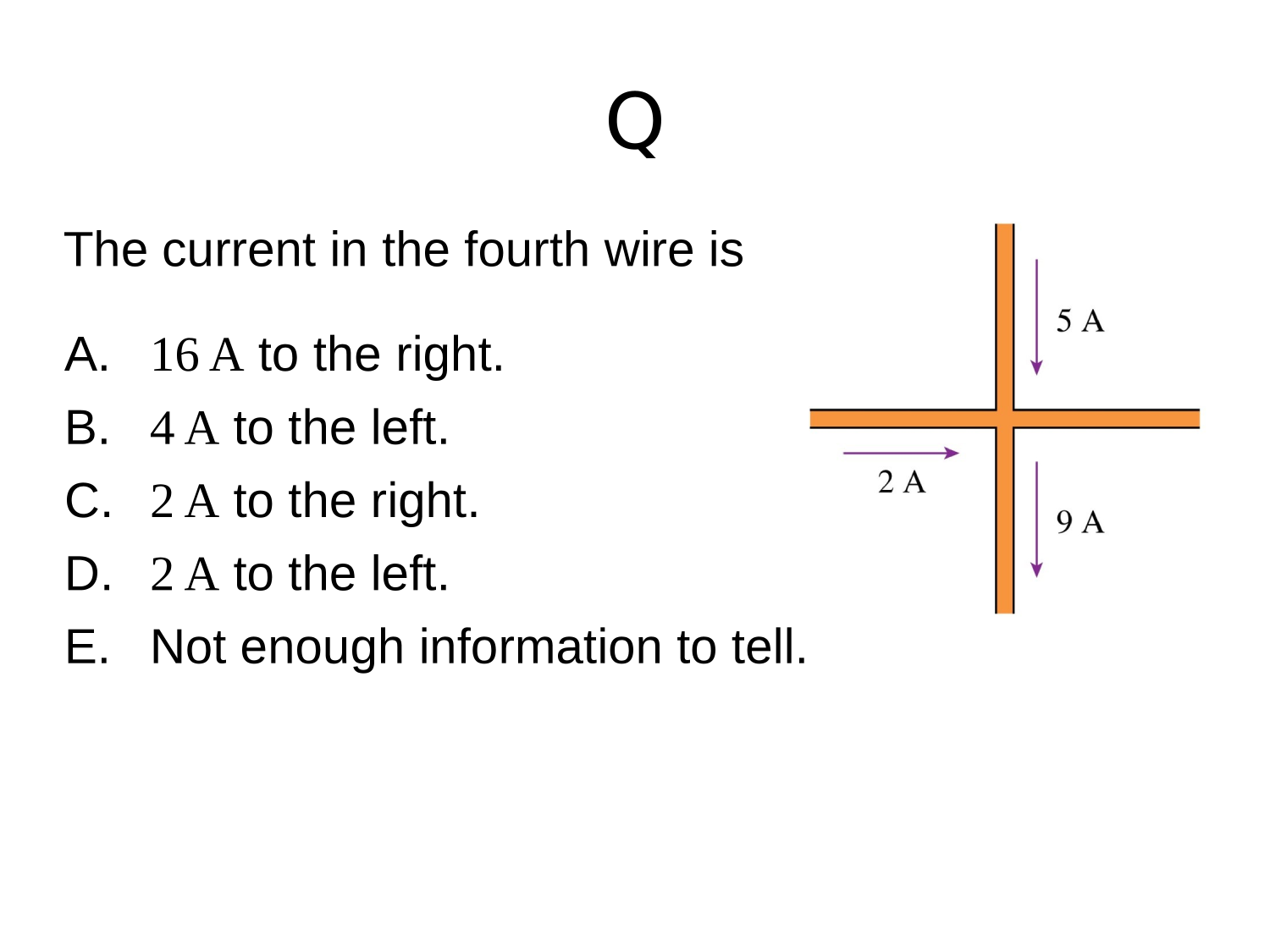
Kirchhoff’s first rule—the junction rule: The sum of all currents entering a junction must equal the sum of all currents leaving the junction:
\Sigma I_\text{in}=\Sigma I_\text{out}

DC-circuits
Kirchhoff's Rules
Conservation of Current
DC-circuits
Kirchhoff's Rules
Conservation of Current
I_1=I_2+I_3
=
\Sigma I_\text{out}
\Sigma I_\text{in}
Kirchhoff's Junction Rule
must equal
The sum of all currents entering a junction
The sum of all currents leaving the junction.
DC-circuits
Kirchhoff's Rules
Conservation of Current
\Sigma I_\text{in}
Kirchhoff's Junction Rule
must equal
The sum of all currents entering a junction
The sum of all currents leaving the junction.
=
\Sigma I_\text{out}
DC-circuits
Kirchhoff's Rules
Conservation of Current
Kirchhoff’s first rule—the junction rule: The sum of all currents entering a junction must equal the sum of all currents leaving the junction:
\Sigma I_\text{in}=\Sigma I_\text{out}
DC-circuits
Kirchhoff's Rules
Conservation of Current
DC-circuits
Kirchhoff's Rules
The Loop Rule
DC-circuits
Extra Resources
Section 10.3
Kirchhoff's Rules
DC-circuits
Kirchhoff's Rules
Textbook
Section 10.3
Charging and Discharging a Capacitor
DC-Circuits
The flow of electric charges
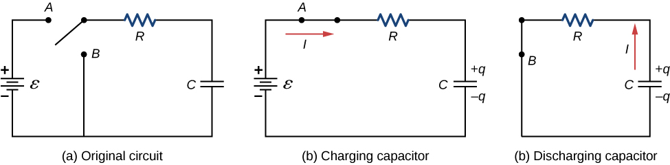
- A circuit containing a source of EMF, a resistor, an uncharged capacitor, and a switch.
DC-circuits
Charging/Discharging a Capacitor
RC in series
- Connect the switch to point A, which completes a circuit. The potential difference established by the battery drives a current that accumulates charge on the capacitor.
- Connect the switch to point B, which completes a different circuit. The established potential difference across the capacitor drives a current through the resistor.
- (a) circuit contains a source of EMF, a resistor, an uncharged capacitor, and a switch.
DC-circuits
Charging/Discharging a Capacitor
RC in series
| what is the charge on the capacitor? | |
| what is the potential difference across the capacitor? | |
| what is the potential difference across the resistor? | |
| What is the current through the resistor (supplied by the EMF source) ? |
@ before switch is connected to either A or B
0
0
0
0
- (b) Connect the switch to (A) and start a timer (t=0)
| what is the charge on the capacitor? | |
| what is the potential difference across the capacitor? | |
| what is the potential difference across the resistor? | |
| What is the current through the resistor (supplied by the EMF source) ? |
@ t=0 (immediately after switch is connected)
\mathcal{E}
0
0
\frac{\mathcal{E}}{R}
DC-circuits
Charging/Discharging a Capacitor
RC in series
| what is the charge on the capacitor? | |
| what is the potential difference across the capacitor? | |
| what is the potential difference across the resistor? | |
| What is the current through the resistor (supplied by the EMF source) ? |
@ t=t (some short time after switch ...)
\mathcal{E}-\frac{q(t)}{C}
\frac{q(t)}{C}
q(t)
\frac{\mathcal{E}}{R}-\frac{q(t)}{RC}
DC-circuits
Charging/Discharging a Capacitor
RC in series
- (b) Connect the switch to (A) and start a timer (t=0)
I=\frac{\mathcal{E}}{R}-\frac{q(t)}{RC}
\text{i.e.}\quad\frac{dq}{dt}=\frac{\mathcal{E}}{R}-\frac{q(t)}{RC}
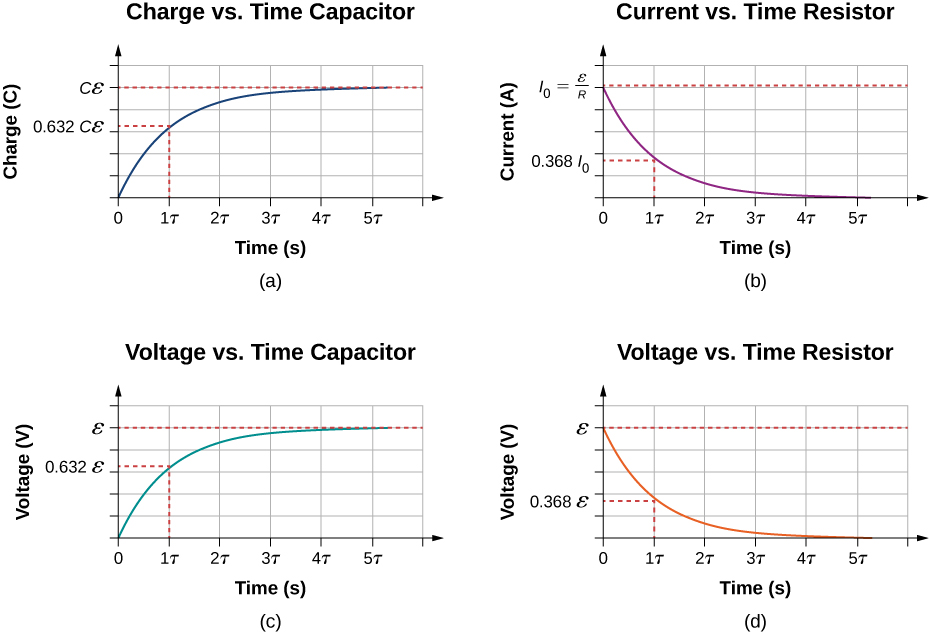
q(t)=C{\mathcal{E}}\left(1-e^{-\frac{t}{RC}}\right)
\text{solve for}\quad q(t)
DC-circuits
Charging/Discharging a Capacitor
RC in series
- (b) Connect the switch to (A) and start a timer (t=0)
@just after
Capacitor carries no charge
@long_time
Capacitor carries maximum charge
q(t)=C{\mathcal{E}}\left(1-e^{-\frac{t}{RC}}\right)
| what is the charge on the capacitor? | |
| what is the potential difference across the capacitor? | |
| what is the potential difference across the resistor? | |
| What is the current through the resistor (supplied by the EMF source) ? |
C{\mathcal{E}}
{\mathcal{E}}
0
0
@ t= (long time after switch ...)
\infty
DC-circuits
Charging/Discharging a Capacitor
RC in series
- (b) Connect the switch to (A) and start a timer (t=0)
I=\frac{dq}{dt}
=\frac{d}{dt}C{\mathcal{E}}\left(1-e^{-\frac{t}{RC}}\right)
=\frac{\mathcal{E}}{R}\ e^{-\frac{t}{RC}}
=I_0\ e^{-\frac{t}{\tau}}
DC-circuits
Charging/Discharging a Capacitor
RC in series
- (b) Connect the switch to (A) and start a timer (t=0)
@just after
Capacitor draws maximum current
@long_time
Capacitor draws
no current
q(t)=C{\mathcal{E}}\left(1-e^{-\frac{t}{RC}}\right)
I(t)=I_0\ e^{-\frac{t}{\tau}}
DC-circuits
Charging/Discharging a Capacitor
RC in series
|
|
|||
| (a) The switch has been open for a long time | |||
| (b) Just after the switch is closed | |||
| (c) A long time after the switch has been closed |
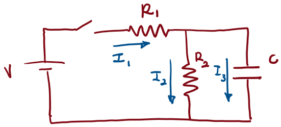
I_1
I_2
I_3
Check your understanding
0
0
0
\frac{V}{R_1}
0
\frac{V}{R_1}
\frac{V}{R_1+R_2}
\frac{V}{R_1+R_2}
0
DC-circuits
Charging/Discharging a Capacitor
RC in series
- (b) Connect the switch to (B) and start a new timer (t=0)
@t=0 (immediately after switch is connected to B)
DC-circuits
Charging/Discharging a Capacitor
RC in series
| what is the charge on the capacitor? | |
| what is the potential difference across the capacitor? | |
| what is the potential difference across the resistor? | |
| What is the current through the resistor (supplied by the EMF source) ? |
C{\mathcal{E}}
{\mathcal{E}}
\frac{{\mathcal{E}}}{R}
{\mathcal{E}}
- (b) Connect the switch to (B) and start a new timer (t=0)
DC-circuits
Charging/Discharging a Capacitor
RC in series
| what is the charge on the capacitor? | |
| what is the potential difference across the capacitor? | |
| what is the potential difference across the resistor? | |
| What is the current through the resistor (supplied by the EMF source) ? |
@ t=t (some short time after switch ...)
\frac{q(t)}{C}
\frac{q(t)}{C}
q(t)
\frac{q(t)}{RC}
- (b) Connect the switch to (B) and start a new timer (t=0)
DC-circuits
Charging/Discharging a Capacitor
RC in series
I=-\frac{q(t)}{RC}
\text{i.e.}\quad\frac{dq}{dt}=-\frac{q(t)}{RC}
q(t)=C{\mathcal{E}}\left(e^{-\frac{t}{RC}}\right)
\text{solve for}\quad q(t)
@just after
Capacitor carries no charge
@long_time
Capacitor carries maximum charge
q(t)=C{\mathcal{E}}\left(e^{-\frac{t}{RC}}\right)
I(t)=-I_0\ e^{-\frac{t}{\tau}}
DC-circuits
Charging/Discharging a Capacitor
RC in series
DC-circuits
Simulator
| Use the sliders to adjust the battery voltage, the resistor's resistance, the plate area, and the plate separation. Use the check boxes to open and close the switch, as well as turn the animation on one off. When animation is turned off, you can use the step buttons to advance time forward or backward in small steps. |
Charging/Discharging a Capacitor
DC-circuits
By drmoussaphysics