Linux Diving
- A Beginner's Journey
about me
EE degree back in 1982
Z80 was the most popular CPU
Pascal/Fortran/COBOL were popular languages
Apple ][ + BASIC and CP/M
intel 80386SX PC mother board designer
......
Interested in Linux since 2016

Z80 CPU

intel 80386SX CPU
photo source: wikipedia.org

Apple ][
marconi.jiang@gmail.com
HOW LINUX WORKS
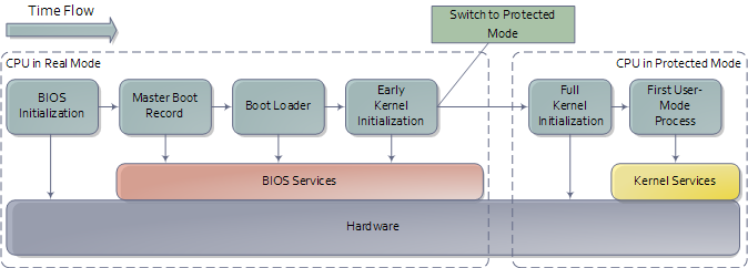
I. HOW LINUX KERNEL BOOTS
-
The machine’s BIOS or boot firmware loads and runs a boot loader.
(Boot Loader 是在作業系統核心運行之前的一段小程式,依附於硬體上執行) -
The boot loader finds the kernel image on disk, loads it into memory, and starts it.
(boot loader 從硬碟或其它周邊選擇系統核心程式所在,載入到記憶體內執行,為作業系統準備好環境設定。) -
The kernel initializes the devices and its drivers.
(初始化硬體設備及其驅動程式) -
The kernel mounts the root filesystem.
(掛載根目錄。根目錄指檔案系統的最上一級目錄,它是相對子目錄來說的;它如同一棵大樹的“根”一般,所有的樹枝以它為起點) -
The kernel starts a program called init with a process ID of 1. This point is the user space start.
(核心啟動初始化程式 init,從這裡開始虛擬記憶體劃分出使用者空間,與核心空間 kernel space 對應) -
init sets the rest of the system processes in motion
-
At some point, init starts a process allowing you to log in, usually at the end or near the end of the boot.
STARTUP MESSAGES
有兩種方式可以查看內核引導和運行診斷資訊
- 查看內核系統日誌檔案。檔案路徑: /var/log/kern.log
- 執行 dmesg 命令
KERNEL INITIALIZATION AND BOOT OPTIONS
在啟動時,Linux內核初始化的順序如下:
- CPU inspection (檢查CPU)
- Memory inspection (檢查記憶體)
- Device bus discovery (發現設備匯流排)
- Device discovery (發現設備)
- Auxiliary kernel subsystem setup (networking, and so on)
(輔助核心子系統啟動,例如網路等) - Root filesystem mount (掛載根目錄)
- User space start (啟動用戶空間)
ROOT FILESYSTEM

* 1
* 2
* 3
KERNEL PARAMETERS
檔案/proc/cmdline記錄了系統內核啟動參數:
$cat /proc/cmdline
BOOT_IMAGE=/boot/vmlinuz-4.4.0-78-generic root=UUID=f9a850a7-4833-4095-9820-b092f313cf05 ro quiet splash
查看運行級別:
$who -r
         run-level 5  2017-08-08 00:48
II. HOW USER SPACE STARTS
用戶空間啟動順序:
- init
- 必要的低層服務例如:udevd 和 syslog
- 網路配置
- 中高層服務例如 :cron , printing
- 登錄提示、圖形界面及其它高層次應用
Init - 天字第一號行程(process)
init(initialization的簡寫)是 Unix 和類 Unix 系統中用來產生其它所有行程(process)的程式。它以系統服務 (daemon) 的方式存在,其行程號碼為1。Linux 系統在開機時載入 Linux 核心後,便由 Linux 核心載入init 程序,由 init 程式完成餘下的開機過程,比如載入運行級別,載入服務,引導 Shell 及圖形化界面等等。
// Linux
$ps -ef | grep init
root 1 0 0 15:16 ? 00:00:01 /sbin/init splash
// Mac OS
$ ps -ef | grep init
0 201 1 0 11:53PM ?? 0:00.06 /System/Library/CoreServices/CrashReporterSupportHelper server-init
0 241 1 0 11:53PM ?? 0:00.17 /usr/libexec/secinitd
501 364 1 0 11:53PM ?? 0:02.18 /usr/libexec/secinitd
0 474 1 0 11:53PM ?? 0:00.18 /System/Library/CoreServices/SubmitDiagInfo server-init
0 993 1 0 6:52AM ?? 0:00.12 /usr/libexec/secinitd
在Linux發行版中,init有三種主要的實現形式:
- System V init: 傳統的
- systemd: 所有主流Linux發行版中的標準init
- Upstart: Ubuntu
Android 和 BSD (運行存放於 ’/etc/rc’ 的初始化 shell 指令碼或直譯式程式)也有它們自己的 init 版本,一些發行版也將System V init 修改為類似 BSD 風格的實現。目前大部分 Linux 發行版都已採用新的 systemd 替代 System V 和 Upstart,但systemd 向下相容 System V。
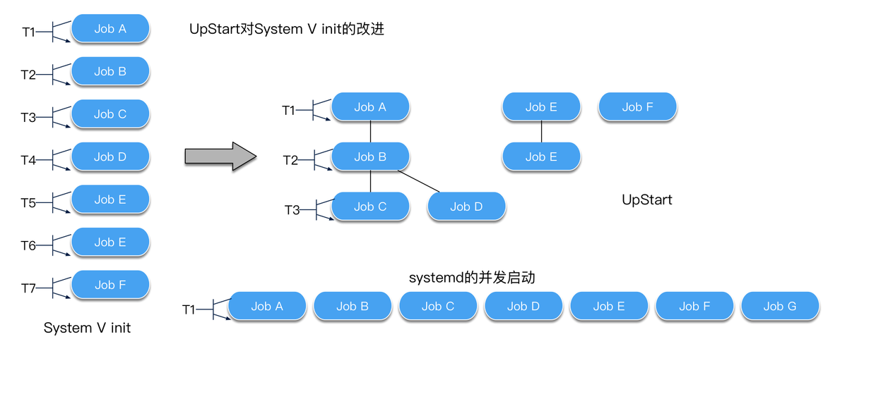
1. System V init
存在一個啟動序列,同一時間只能啟動一個任務,這種架構下,很容易解決依賴問題,但是性能方面要受一些影響。
2. systemd is goal oriented
針對 System V init 的不足,systemd 所有的服務都並發啟動。systemd 時基於目標的,需要定義要實現的目標,以及它的依賴項。systemd 將所有過程都抽象為一個配置單元,即 unit。可以認為一個服務是一個配置單元;一個掛載點是一個配置單元。
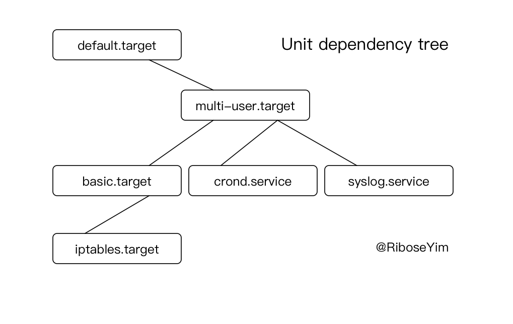
3. Upstart is reactionary
Upstart 是基於事件的,Upstart 的事件驅動模型允許它以非同步方式對生成的事件作出回應。
III. THE INITIAL RAM FILESYSTEM
Linux 核心不能通過存取 PC BIOS 或者 EFI 介面從磁碟獲取數據,所以為了 mount 它的 root filesystem, 對於底層存儲需要驅動程式支援。解決方案是在核心運行之前,由 boot loader 載入驅動模組及工具到記憶體。在啟動時,核心讀取相關模組到一個臨時的RAM filesystem (initramfs), 掛載在/根目錄下, initramsfs 允許核心為真正的 root filesystem 載入必要的驅動模組。
最後,再掛載真正的 root filesystem、啟動init。
Linux在很多場景下都需要建立一個基於記憶體的檔案系統,提供一個可以接近零延遲的快速存儲區域。目前有兩類主要的RAM磁碟可用,她們個有優劣:ramfs 和 tmpfs。(注意:建立之前使用 free 命令查看未使用的RAM)
# free
              total        used        free      shared  buff/cache   available
Mem:        1012720      168756       23576       52024      820388      754520
Swap:        262140          88      262052

# mkdir /mnt/ramdisk
# mount -t tmpfs -o size=512m tmpfs /mnt/ramdisk
# vi /etc/fstab
# tmpfs /mnt/ramdisk tmpfs nodev,nosuid,noexec,nodiratime,size=1024M 0 0
Motherboard Chipsets and the Memory Map
How Computers Boot Up
The Kernel Boot Process
Motherboard Chipsets and the Memory Map
This section describes the layout of modern Intel-based motherboards, how the CPU accesses memory and the system memory map. To start off let’s take a look at how an Intel computer is wired up nowadays. The diagram below shows the main components in a motherboard and dubious color taste.
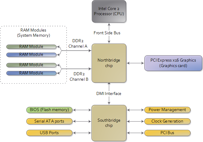
CPU Adress
There are three main ways by which the CPU and the outside communicate: memory address space, I/O address space, and interrupts. We only worry about motherboards and memory for now.
In a motherboard the CPU’s gateway to the world is the front-side bus connecting it to the northbridge. Whenever the CPU needs to read or write memory it does so via this bus. IIt uses some pins to transmit the physical memory address it wants to write or read, while other pins send the value to be written or receive the value being read. An Intel Core 2 QX6600 has 33 pins to transmit the physical memory address (so there are 2^33 choices of memory locations) and 64 pins to send or receive data (so data is transmitted in a 64-bit data path, or 8-byte chunks). This allows the CPU to physically address 64 gigabytes of memory (2^33 locations * 8 bytes) although most chipsets only handle up to 8 gigabytes of RAM.
We’re used to thinking of memory only in terms of RAM, the stuff programs read from and write to all the time. And indeed most of the memory requests from the processor are routed to RAM modules by the northbridge. But not all of them. Physical memory addresses are also used for communication with assorted devices on the motherboard (this communication is called memory-mapped I/O). These devices include video cards, most PCI cards (say, a scanner or SCSI card), and also the flash memory that stores the BIOS.
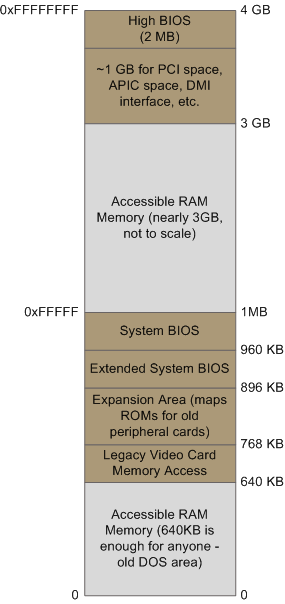
Memory Address Map
When the northbridge receives a physical memory request it decides where to route it: should it go to RAM? Video card maybe?
This routing is decided via the memory address map.
For each region of physical memory addresses, the memory map knows the device that owns that region. The bulk of the addresses are mapped to RAM, but when they aren’t the memory map tells the chipset which device should service requests for those addresses. This mapping of memory addresses away from RAM modules causes the classic hole in PC memory between 640KB and 1MB. A bigger hole arises when memory addresses are reserved for video cards and PCI devices. This is why 32-bit OSes have problems using 4 gigs of RAM. In Linux the file /proc/iomem neatly lists these address range mappings. The diagram below shows a typical memory map for the first 4 gigs of physical memory addresses in an Intel PC
Actual addresses and ranges depend on the specific motherboard and devices present in the computer, but most Core 2 systems are pretty close to the above. All of the brown regions are mapped away from RAM. Remember that these are physical addresses that are used on the motherboard buses. Inside the CPU (for example, in the programs we run and write), the memory addresses are logical and they must be translated by the CPU into a physical address before memory is accessed on the bus.
Logical Address Translation
The rules for translation of logical addresses into physical addresses are complex and they depend on the mode in which the CPU is running (real mode, 32-bit protected mode, and 64-bit protected mode).
Regardless of the translation mechanism, the CPU mode determines how much physical memory can be accessed.
When the CPU is running in 32-bit mode, then it is only capable of physically addressing 4 GB (well, there is an exception called physical address extension, but ignore it for now). Since the top 1 GB or so of physical addresses are mapped to motherboard devices the CPU can effectively use only ~3 GB of RAM.
If the CPU is in real mode, then it can only address 1 megabyte of physical RAM (this is the only mode early Intel processors were capable of).
A CPU running in 64-bit mode can physically access 64GB (few chipsets support that much RAM though). In 64-bit mode it is possible to use physical addresses above the total RAM in the system to access the RAM regions that correspond to physical addresses stolen by motherboard devices. This is called reclaiming memory and it’s done with help from the chipset.
Further Reading - intel CPU / Memory
-
Datasheet for Intel G35 Chipset documents a representative chipset for Core 2 processors. This is the main source for this post.
-
Datasheet for Intel Core 2 Quad-Core Q6000 Sequence is a processor datasheet. It documents each pin in the processor (there aren’t that many actually, and after you group them there’s really not a lot to it). Fascinating stuff, though some bits are arcane.
-
The Intel Software Developer’s Manuals are outstanding. Far from arcane, they explain beautifully all sorts of things about the architecture. Volumes 1 and 3A have the good stuff (don’t be put off by the name, the “volumes” are small and you can read selectively).
-
Pádraig Brady suggested that I link to Ulrich Drepper’s excellent paper on memory. It’s great stuff. I was waiting to link to it in a post about memory, but the more the merrier.
How Computers Boot Up
-
Booting is an involved, hacky, multi-stage affair – fun stuff. Here’s an outline of the process:
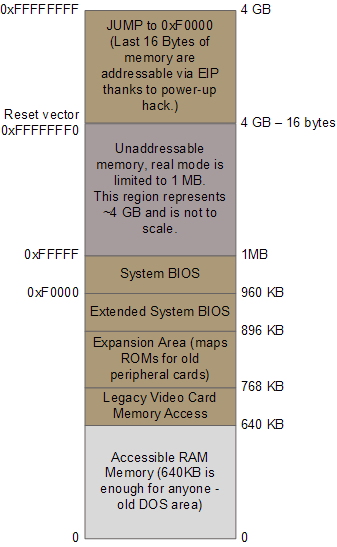
If all hardware is well working and the CPU starts running. In a multi-processor or multi-core system one CPU is dynamically chosen to be the bootstrap processor (BSP) that runs all of the BIOS and kernel initialization code. The remaining processors, called application processors (AP) at this point, remain halted until later on when they are explicitly activated by the kernel. Intel CPUs have been evolving over the years but they’re fully backwards compatible, so modern CPUs canbehave like the original 1978 Intel 8086, which is exactly what they do after power up. In this primitive power up state the processor is in real mode with memory paging disabled. This is like ancient MS-DOS where only 1 MB of memory can be addressed and any code can write to any place in memory – there’s no notion of protection or privilege.
Reset Vector in Real mode
Most registers in the CPU have well-defined values after power up, including the instruction pointer (EIP) which holds the memory address for the instruction being executed by the CPU. Intel CPUs use a hack whereby even though only 1MB of memory can be addressed at power up, a hidden base address (an offset, essentially) is applied to EIP so that the first instruction executed is at address 0xFFFFFFF0 (16 bytes short of the end of 4 gigs of memory and well above one megabyte). This magical address is called the reset vector and is standard for modern Intel CPUs.
The motherboard ensures that the instruction at the reset vector is a jump to the memory location mapped to the BIOS entry point. This jump implicitly clears the hidden base address present at power up. All of these memory locations have the right contents needed by the CPU thanks to the memory map kept by the chipset. They are all mapped to flash memory containing the BIOS since at this point the RAM modules have random crap in them. An example of the relevant memory regions is shown to the right:
POST (Power-On Self Test)
- The CPU then starts executing BIOS code, which initializes some of the hardware in the machine.
- Afterwards the BIOS kicks off the Power-on Self Test (POST) which tests various components in the computer. Lack of a working video card fails the POST and causes the BIOS to halt and emit beeps to let you know what’s wrong, since messages on the screen aren’t an option.
- A working video card takes us to a stage where the computer looks alive: manufacturer logos are printed, memory starts to be tested, angels blare their horns. Other POST failures, like a missing keyboard, lead to halts with an error message on the screen. The POST involves a mixture of testing and initialization, including sorting out all the resources – interrupts, memory ranges, I/O ports – for PCI devices. Modern BIOSes that follow the Advanced Configuration and Power Interface build a number of data tables that describe the devices in the computer, which are later used by the kernel.
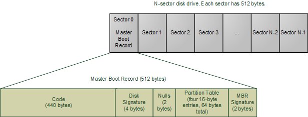
Boot up an OS through MBR
After the POST the BIOS wants to boot up an operating system, which must be found somewhere: hard drives, CD-ROM drives, floppy disks, etc. The actual order in which the BIOS seeks a boot device is user configurable. If there is no suitable boot device the BIOS halts with a complaint like “Non-System Disk or Disk Error.” A dead hard drive might present with this symptom. Hopefully this doesn’t happen and the BIOS finds a working disk allowing the boot to proceed.
The BIOS now reads the first 512-byte sector (sector zero) of the hard disk. This is called the Master Boot Record and it normally contains two vital components: a tiny OS-specific bootstrapping program at the start of the MBR followed by a partition table for the disk. The BIOS however does not care about any of this: it simply loads the contents of the MBR into memory location 0x7c00 and jumps to that location to start executing whatever code is in the MBR.
Linux Diving
By Marconi Jiang
Linux Diving
Personal collections related to Linux - from basics to deep dive - not only software, but covering a little hardware


