PHY2049 depot
A
B
C
Electric Circuits
There are three important physical quantities to keep track of in an electric circuit
Electric Potential
Electric Current
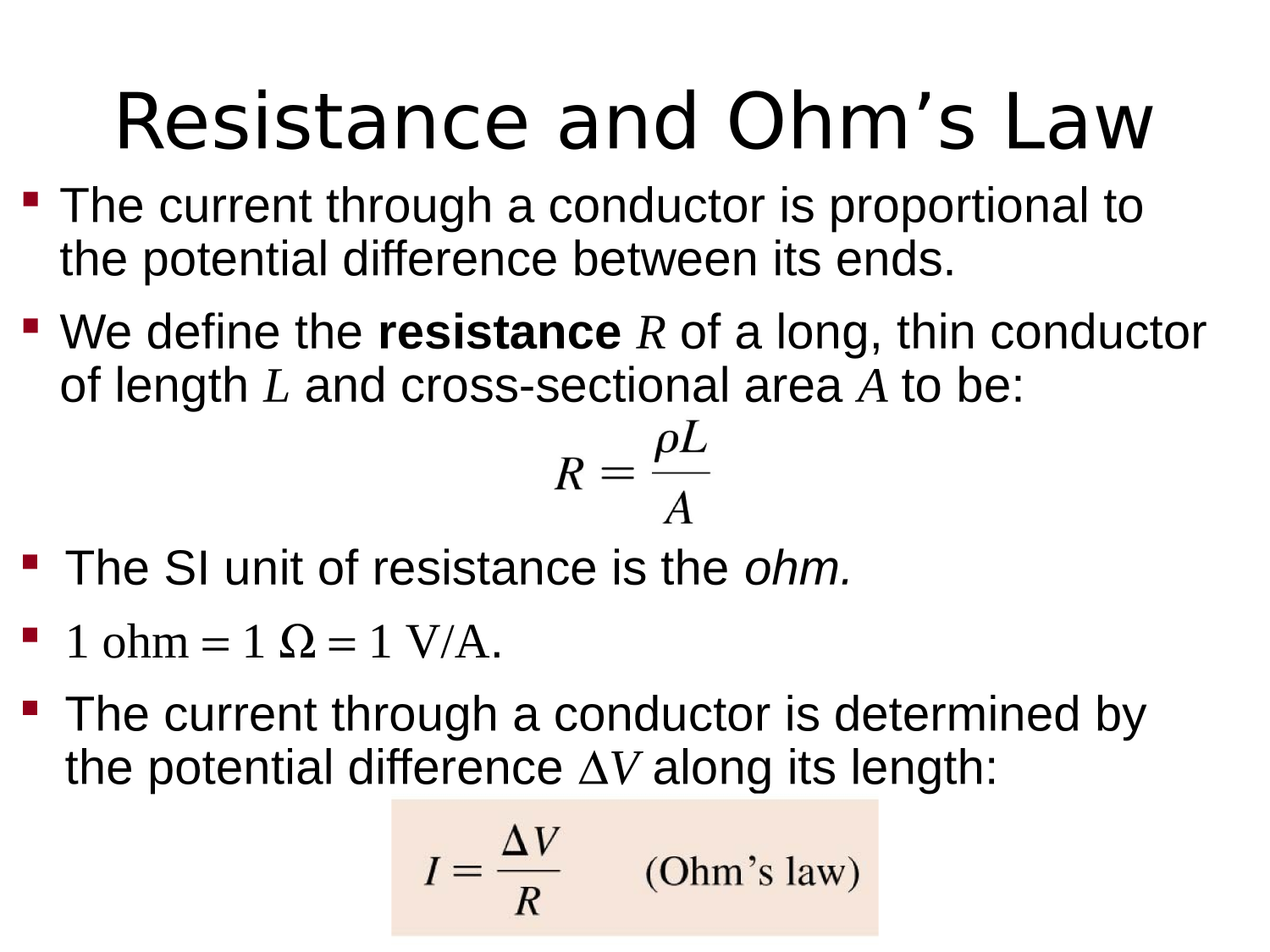
Resistance (Impedance)

First, you need a conductor

as a conduit for electricity
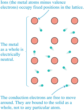
The "conduction" electrons bounce around.
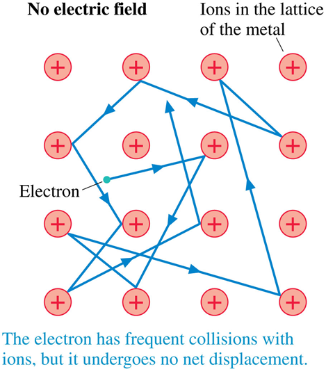
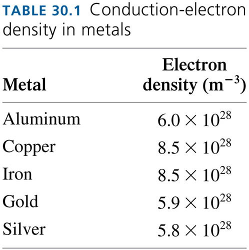
Q: What is the average speed of an electron within the metal?
A: Assuming a simple model of a 3D electron gas @ room temp:
\frac{1}{2}m_e v^2=\frac{3}{2}k_B T
v=\sqrt{\frac{3k_B T}{m_e}}\approx 10^5 \: m/s
\text{Kinetic Energy} = \text{Thermal Energy}
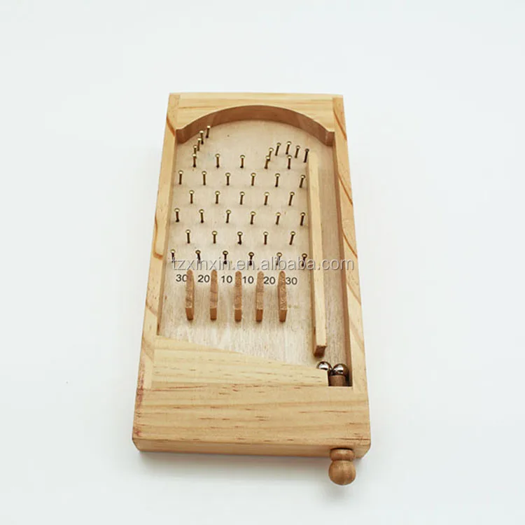
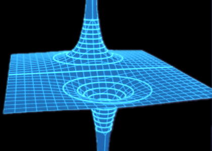
Electric field inside a conductor?!?

Suppose we setup an electric field inside the conductor...
Yes,charges are moving -- this is not electrostatic equilibrium!
How do you setup an electric field inside the conductor?
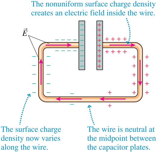
e.g. Discharging a capacitor
modeled here by tilting the board
So we setup an electric field inside the conductor
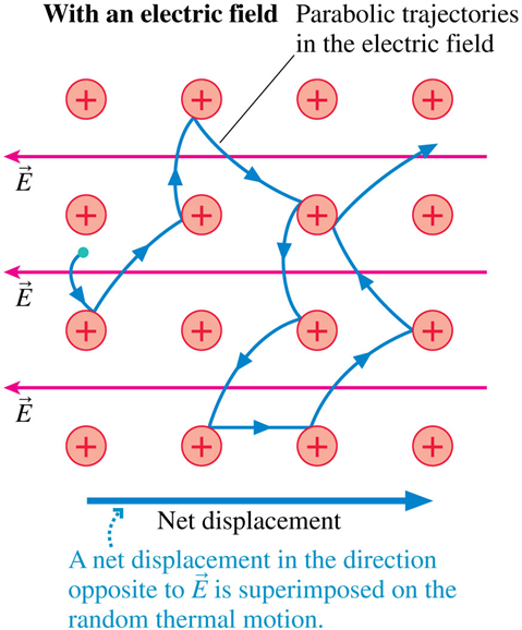
Q: Why are the trajectories parabolic?
A: Projectile motion
\implies \vec{a} = \frac{q_e}{m_e} \vec{E}
\implies q_e \vec{E} = m_e \vec{a}
\Delta\vec{r} = \vec{v}_0 t + \tfrac{1}{2}\vec{a}t^2
Constant acceleration in direction opposite of field,
and constant velocity perpendicular to field.
\vec{F} = m \vec{a}
So we setup an electric field inside the conductor
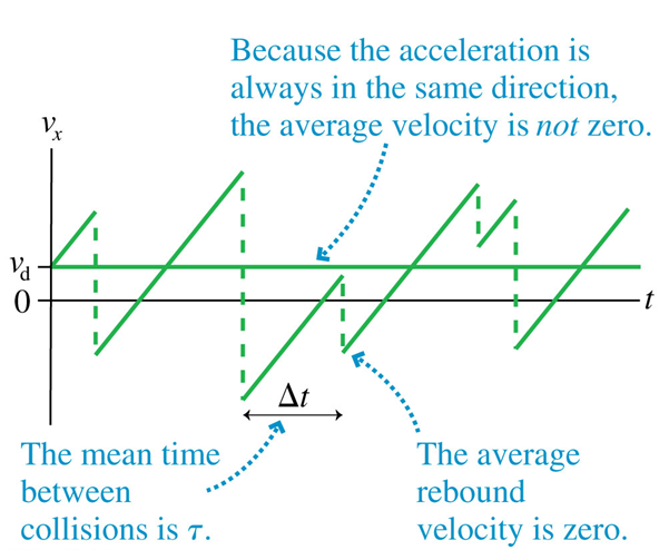
Q: What is the average "drift" velocity?
A: very slow ~
~ 10^{-4} m/s
{v}_{d} = a\ t
v_d = \frac{q_e \tau}{m_e} E
If the average time between collisions is
\tau
then
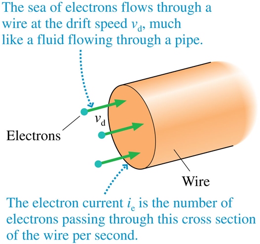
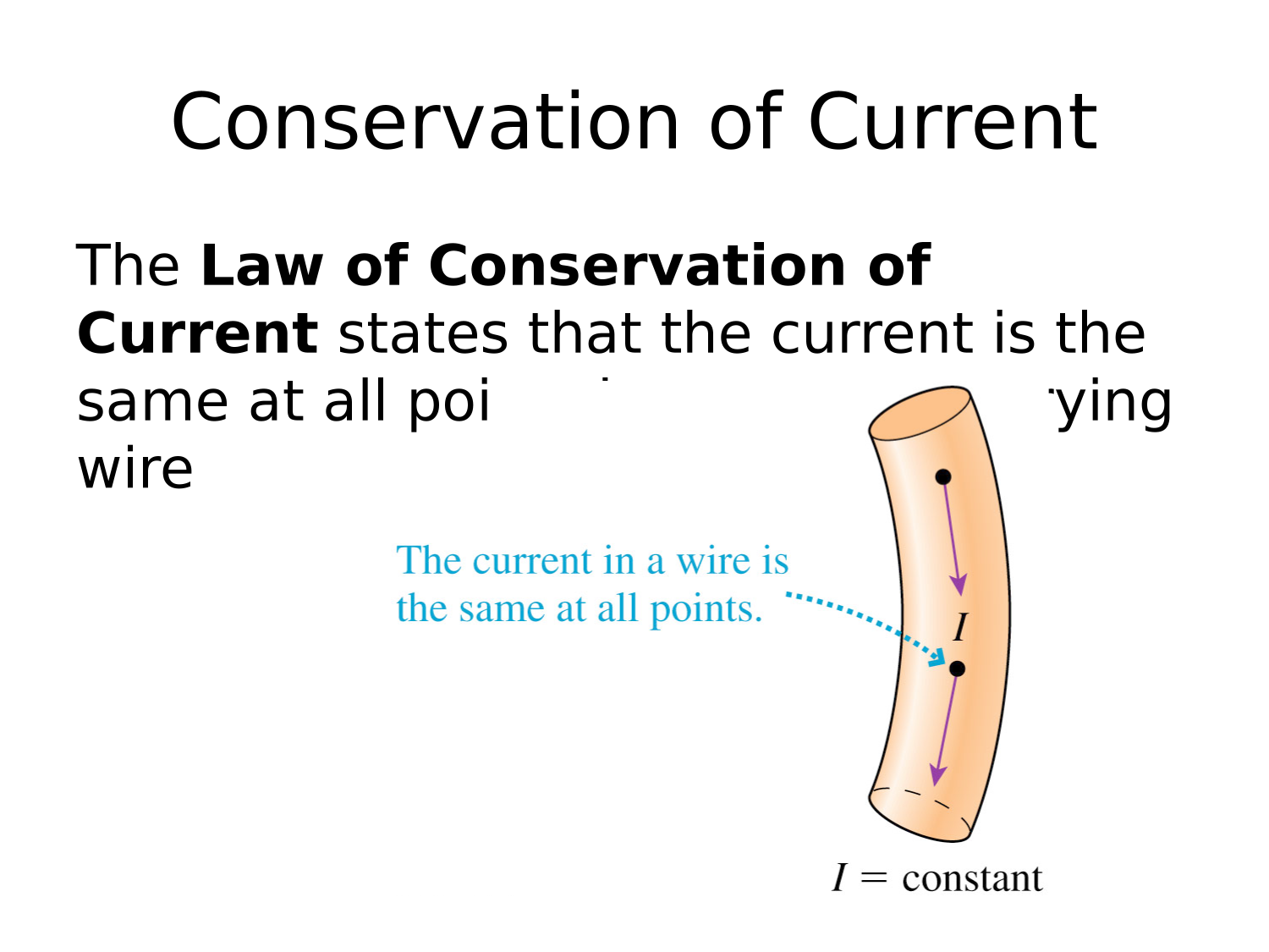
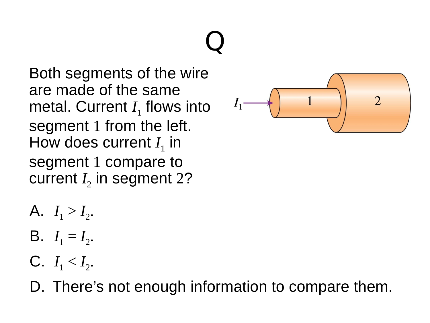
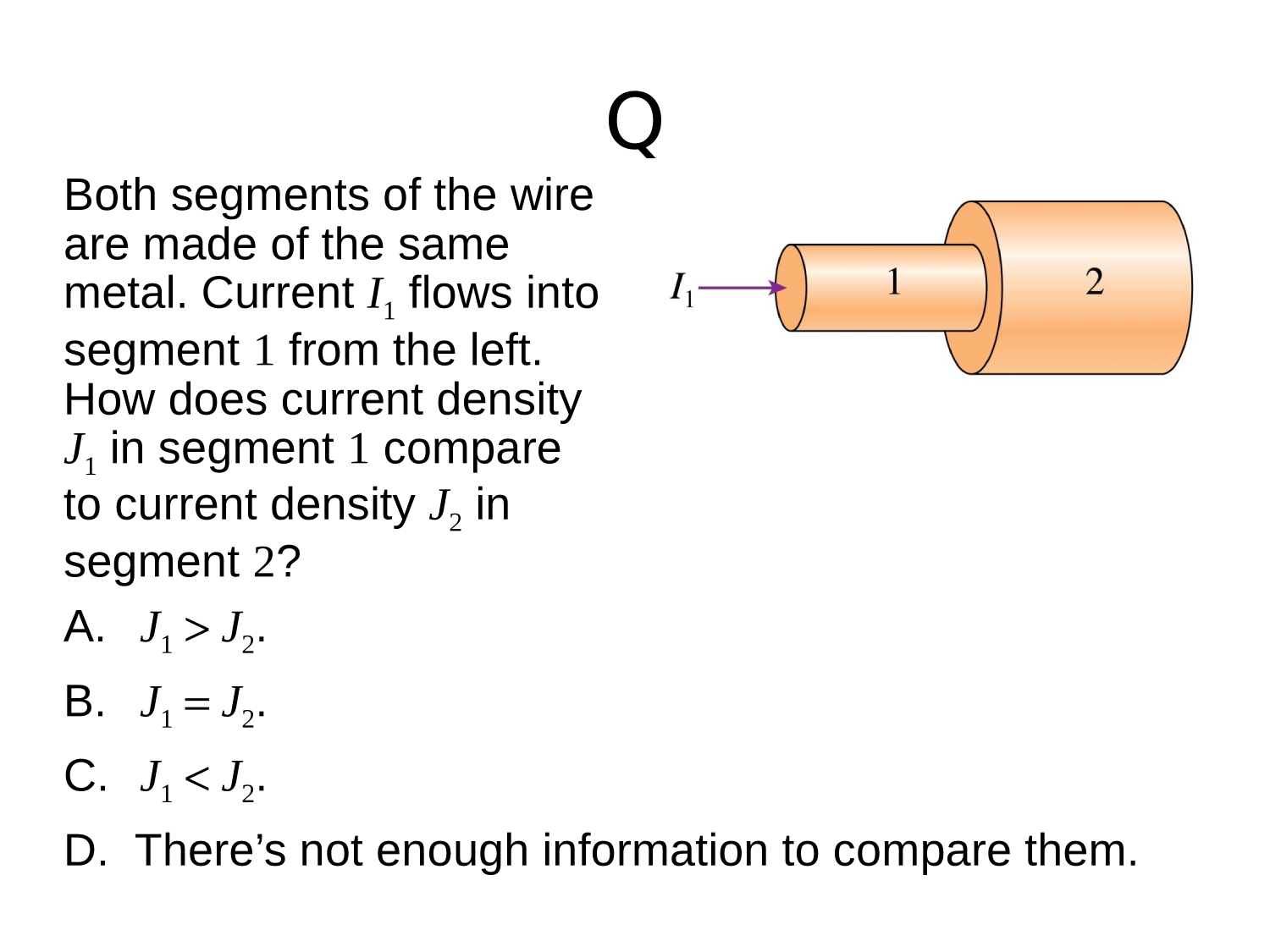
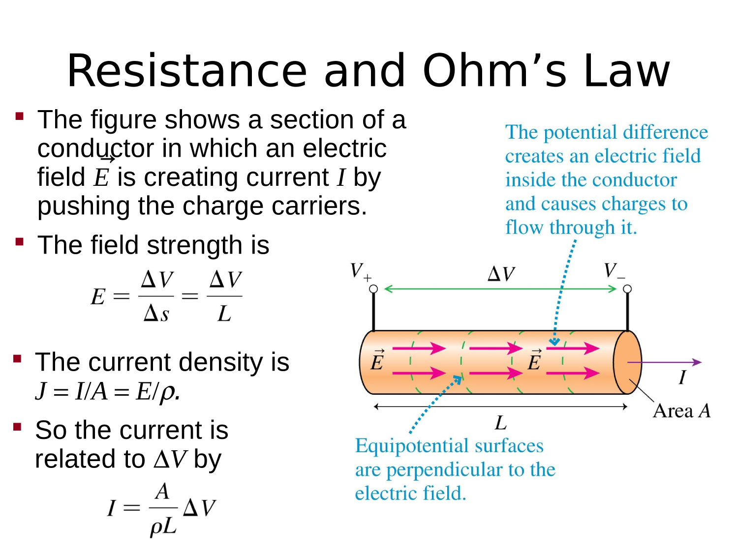
Then, you make a wire


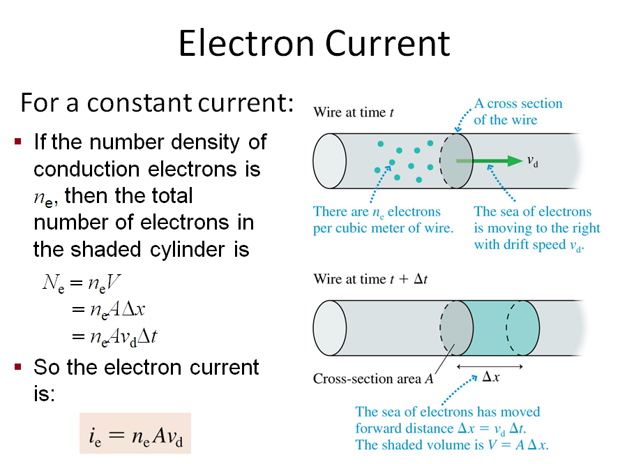
\implies i_e= \frac{n_e\ A\ q_e\ \tau}{m_e} E
Conventional Current
The rate of charge flow in a conductor

I = \frac{dQ}{dt}
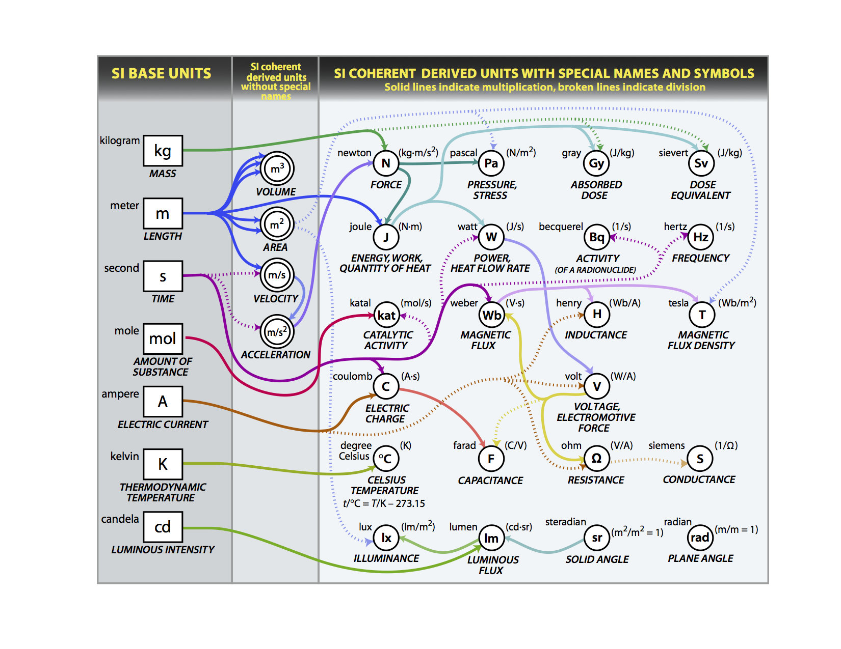
The SI unit for conventional current is the Ampere
A = \frac{C}{s}
Conventional Current
I = \frac{\Delta Q}{\Delta t} = \frac{q_e N_e}{\Delta t} = q_e\ i_e
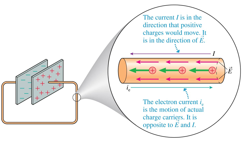
Electron Current
vs
Charging and discharging a capacitor
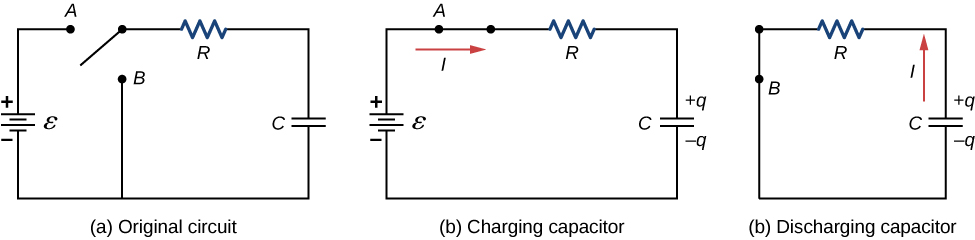
RC in series
- (a) circuit contains a source of EMF, a resistor, an uncharged capacitor, and a switch.
Charging a Capacitor
- (b) Connect the switch to (A) and start a timer (t=0)
| what is the charge on the capacitor? | |
| what is the potential difference across the capacitor? | |
| what is the potential difference across the resistor? | |
| What is the current through the resistor (supplied by the EMF source) ? |
@ t=0 (immediately after switch is connected)
\mathcal{E}
0
0
\frac{\mathcal{E}}{R}
Charging a Capacitor
- (b) Connect the switch to (A) and start a timer (t=0)
| what is the charge on the capacitor? | |
| what is the potential difference across the capacitor? | |
| what is the potential difference across the resistor? | |
| What is the current through the resistor (supplied by the EMF source) ? |
@ t=t (some short time after switch ...)
\mathcal{E}-\frac{q}{C}
\frac{q}{C}
q(t)
\frac{\mathcal{E}}{R}-\frac{q}{RC}
Charging a Capacitor
- (b) Connect the switch to (A) and start a timer (t=0)
I=\frac{\mathcal{E}}{R}-\frac{q}{RC}
\text{i.e.}\quad\frac{dq}{dt}=\frac{\mathcal{E}}{R}-\frac{q}{RC}
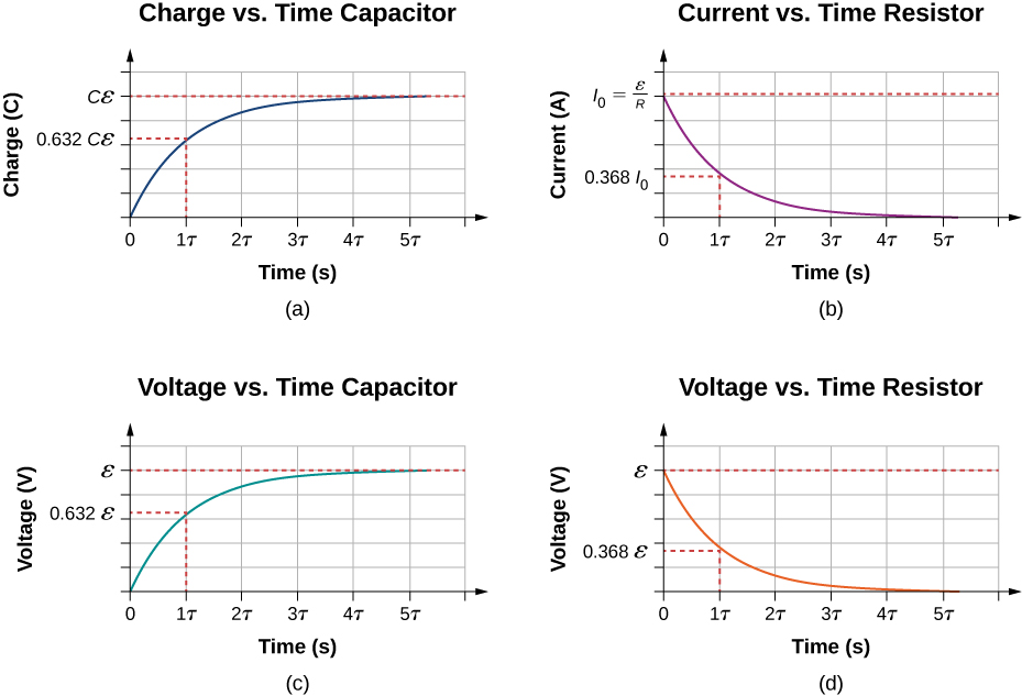
q(t)=C{\mathcal{E}}\left(1-e^{-\frac{t}{RC}}\right)
\text{solve for}\quad q(t)
Charging a Capacitor
- (b) Connect the switch to (A) and start a timer (t=0)
q(t)=C{\mathcal{E}}\left(1-e^{-\frac{t}{RC}}\right)
| what is the charge on the capacitor? | |
| what is the potential difference across the capacitor? | |
| what is the potential difference across the resistor? | |
| What is the current through the resistor (supplied by the EMF source) ? |
C{\mathcal{E}}
{\mathcal{E}}
0
0
@ t= (long time after switch ...)
\infty
Charging a Capacitor
- (b) Connect the switch to (A) and start a timer (t=0)
q(t)=C{\mathcal{E}}\left(1-e^{-\frac{t}{RC}}\right)
I=\frac{dq}{dt}
=\frac{d}{dt}C{\mathcal{E}}\left(1-e^{-\frac{t}{RC}}\right)
=\frac{\mathcal{E}}{R}\ e^{-\frac{t}{RC}}
=I_0\ e^{-\frac{t}{\tau}}
Charging a Capacitor
- (b) Connect the switch to (A) and start a timer (t=0)
q(t)=C{\mathcal{E}}\left(1-e^{-\frac{t}{RC}}\right)
I(t)=I_0\ e^{-\frac{t}{\tau}}
@just after
Capacitor draws maximum current
@long_time
Capacitor draws zero current
Charging a Capacitor
|
|
|||
| (a) The switch has been open for a long time | |||
| (b) Just after the switch is closed | |||
| (c) A long time after the switch has been closed |
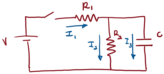
I_1
I_2
I_3
Check your understanding
0
0
0
\frac{V}{R_1}
0
\frac{V}{R_1}
\frac{V}{R_1+R_2}
\frac{V}{R_1+R_2}
0
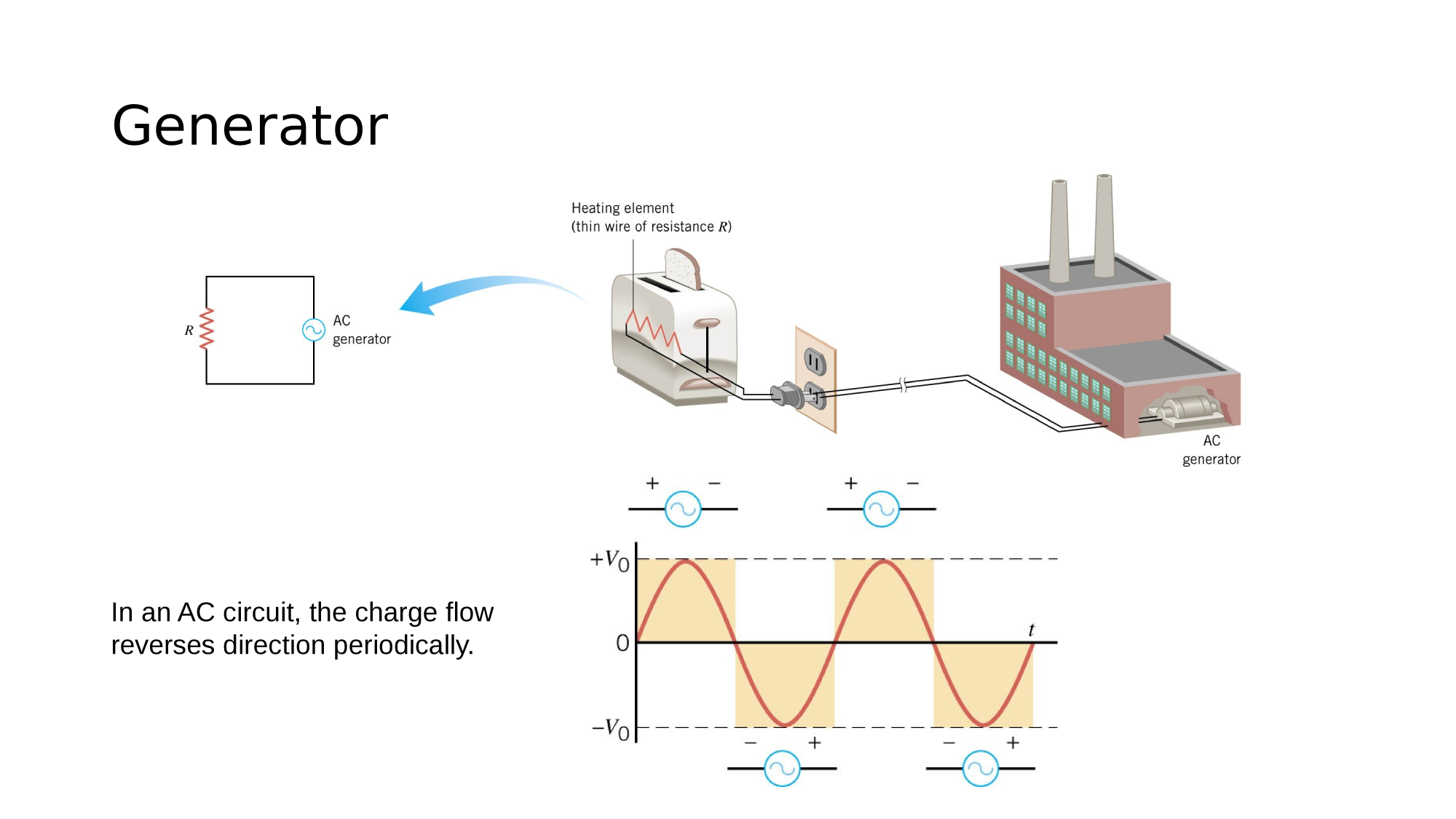
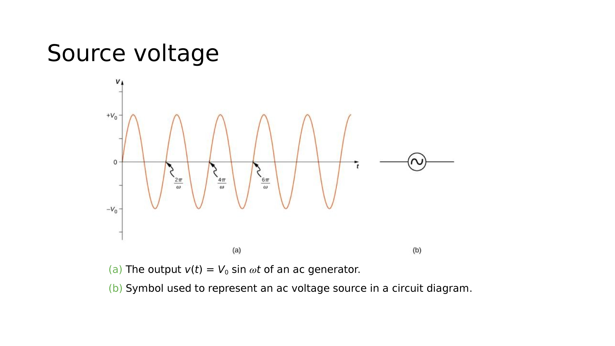
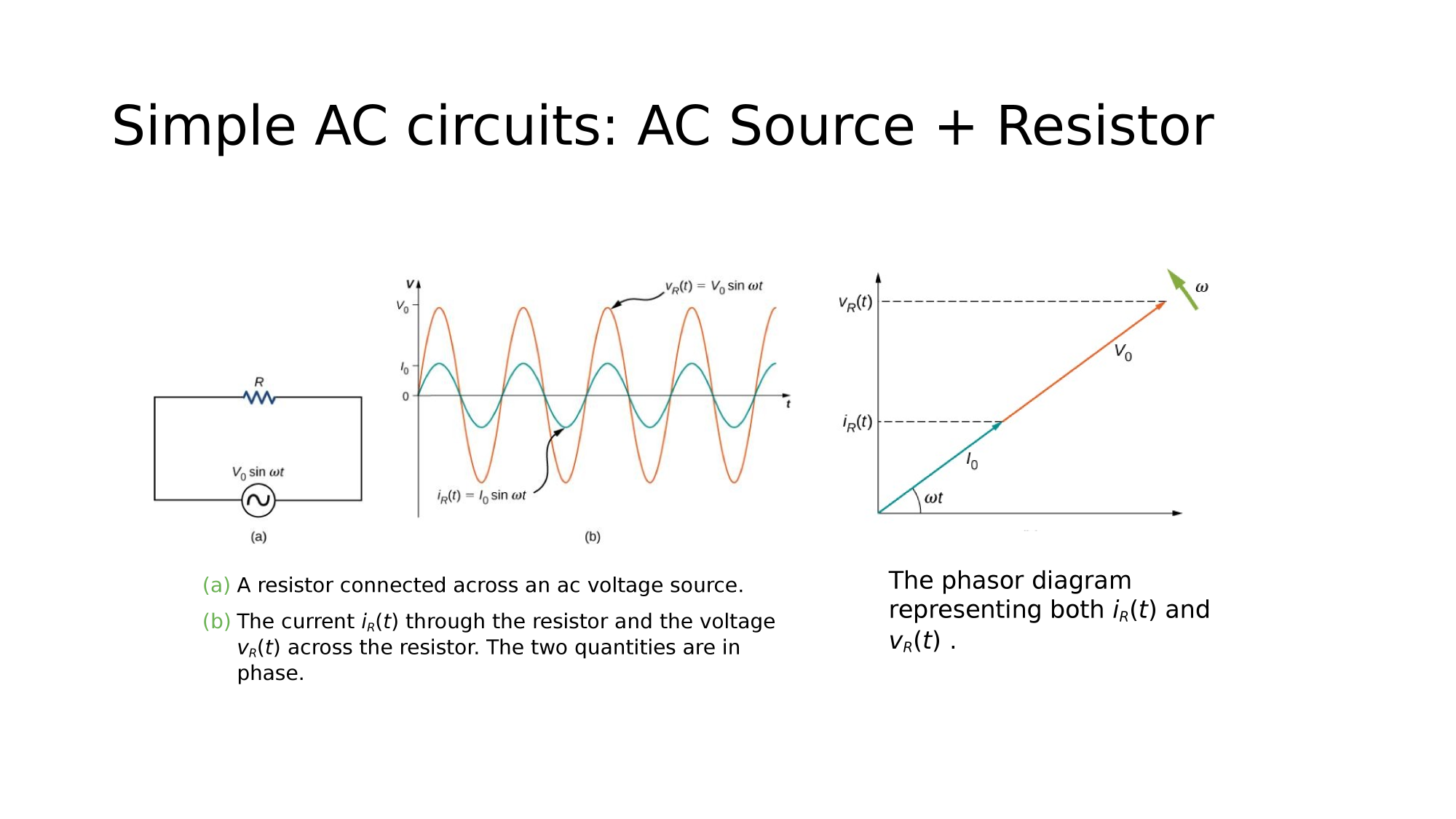
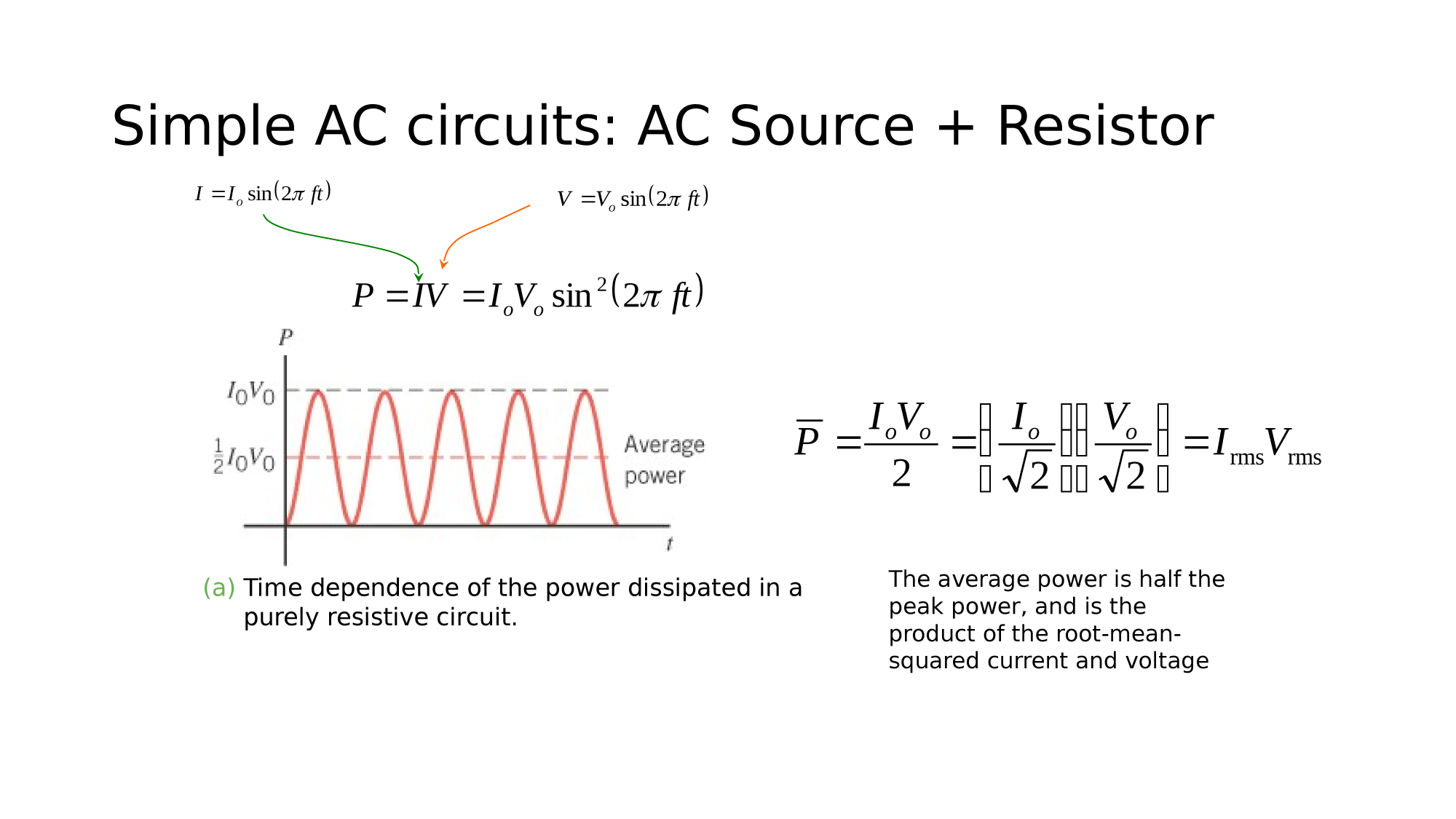
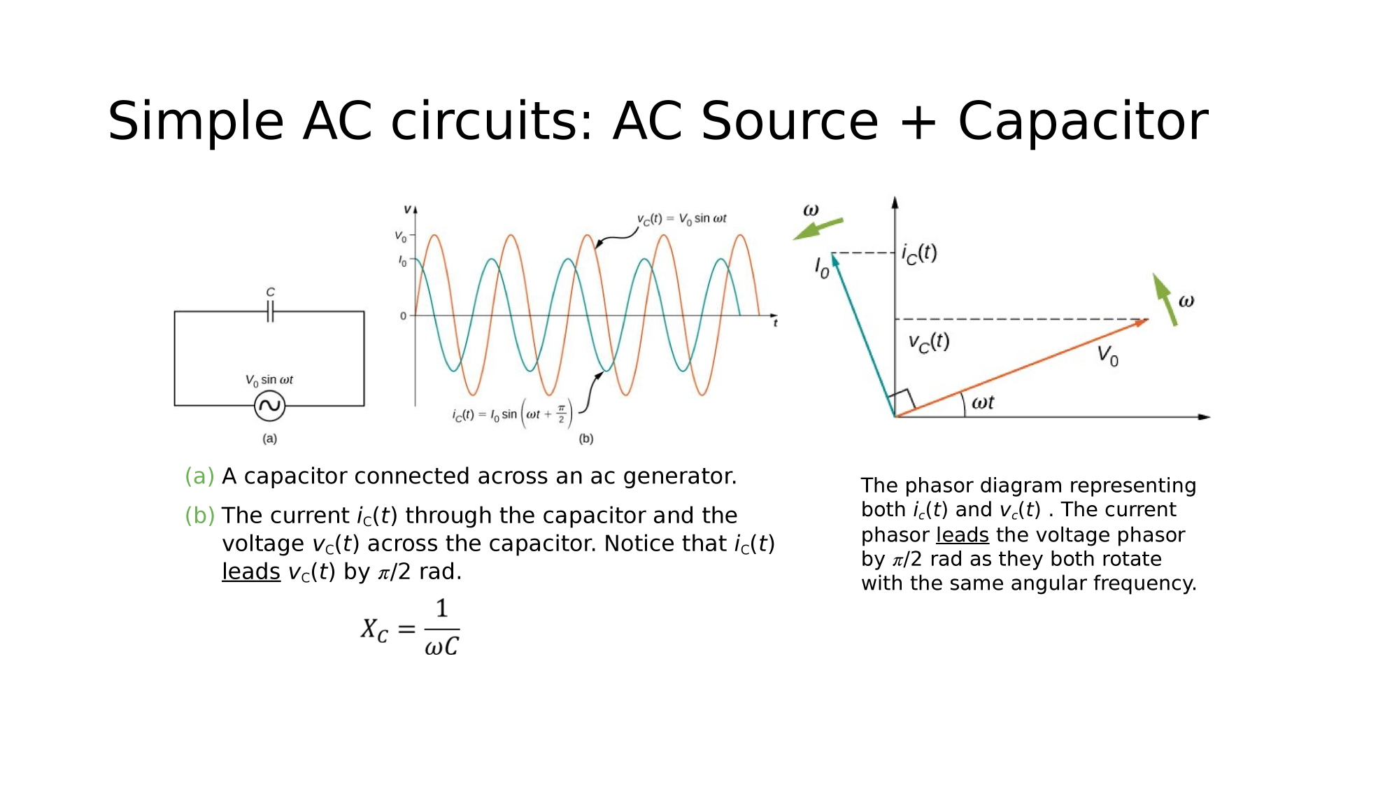
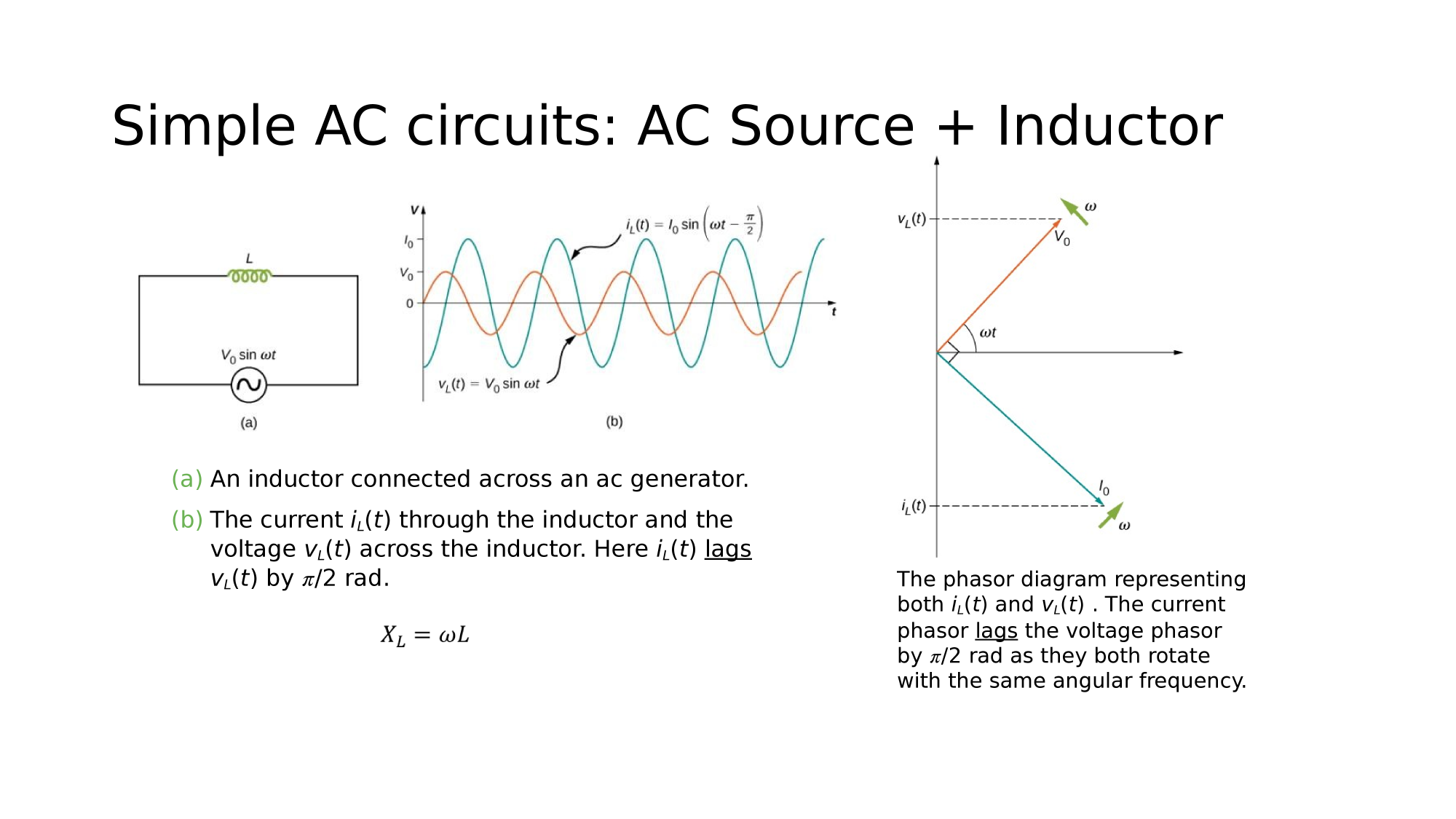
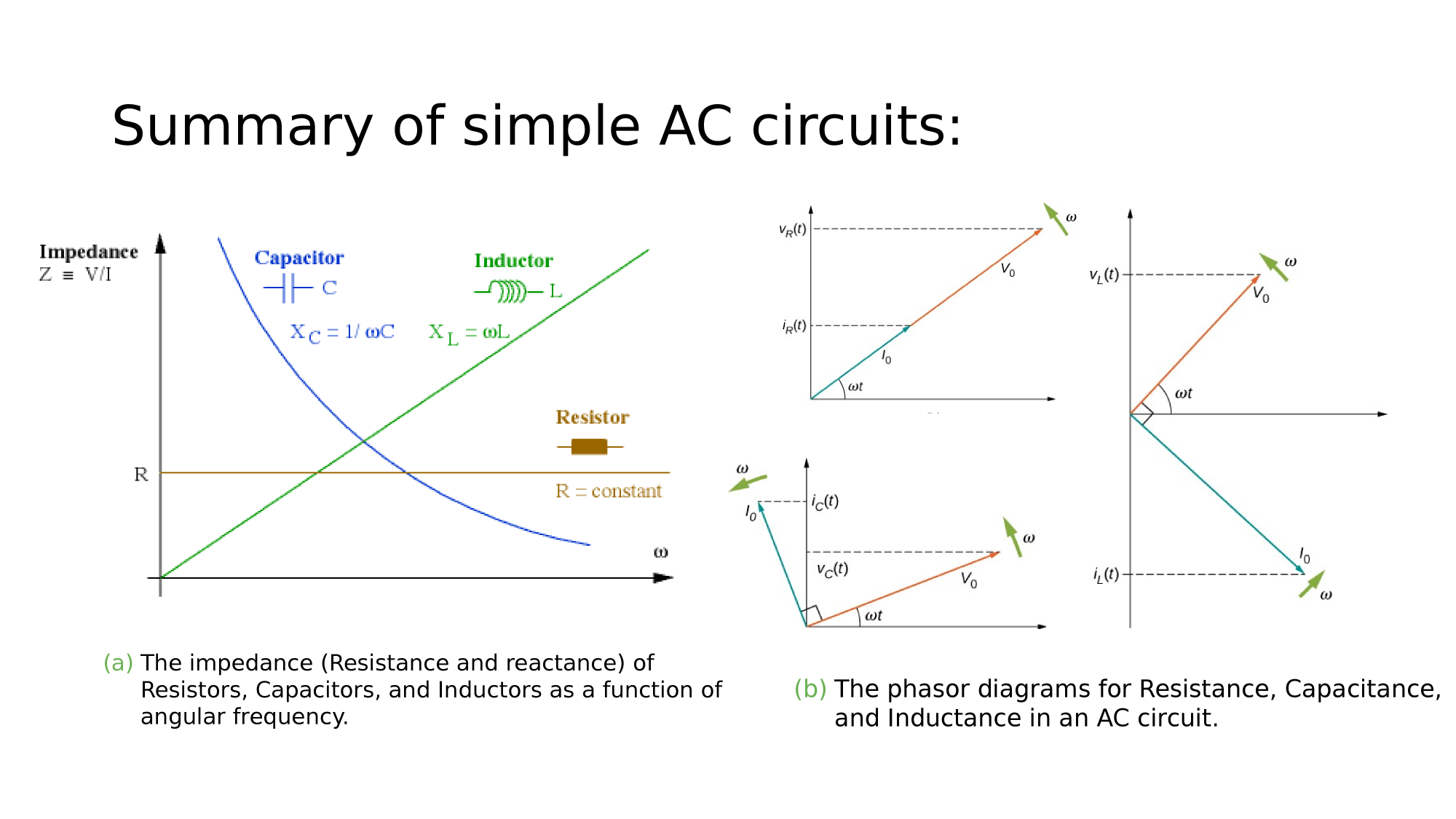
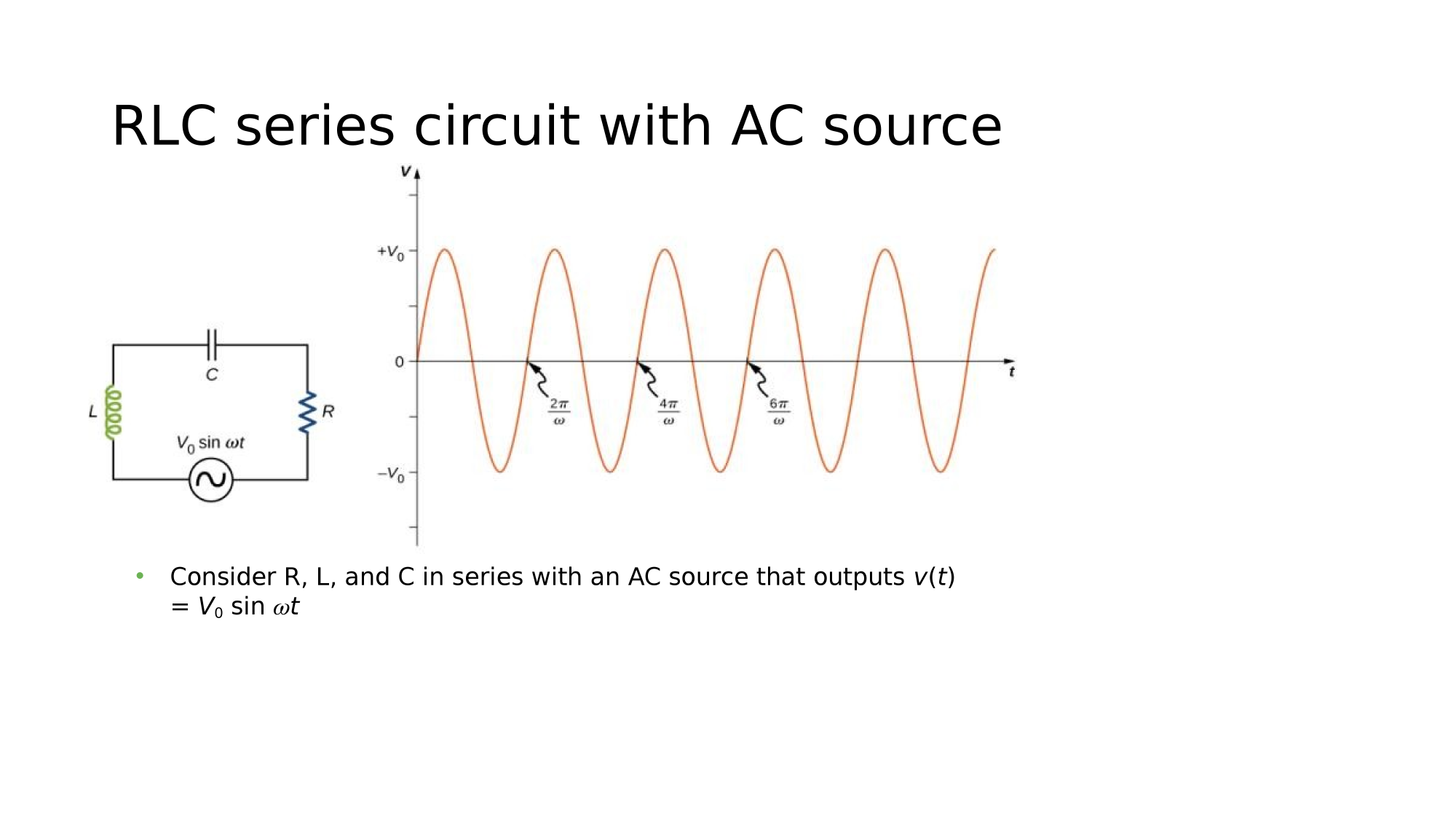
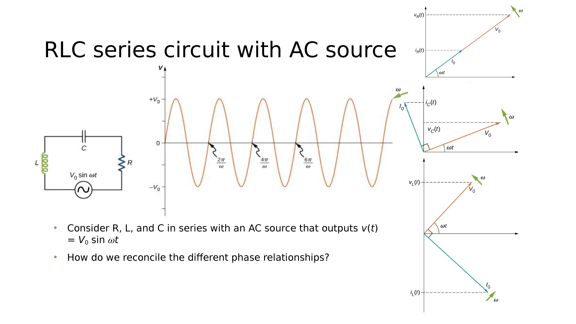
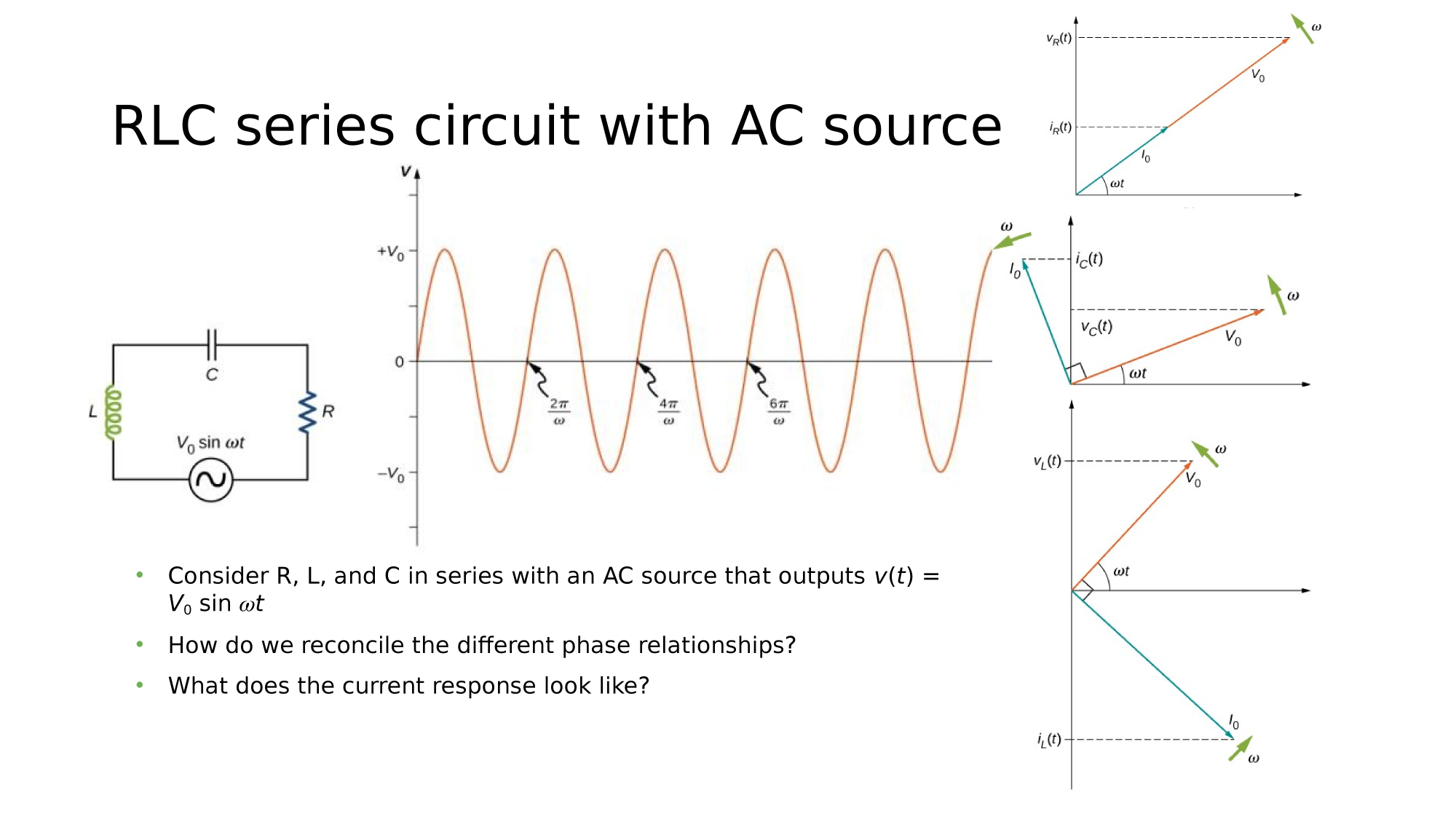
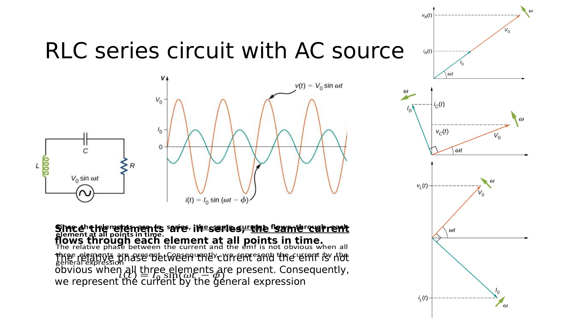
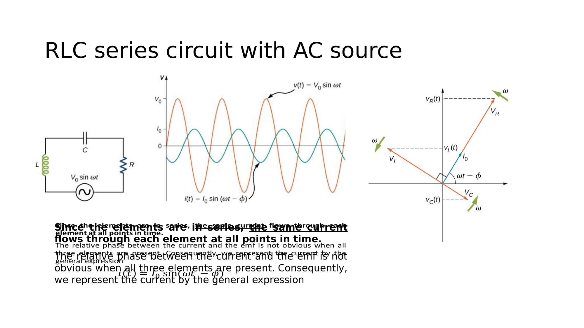
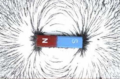
AC-Circuits

Magnetism
Charged Particles
- influence is described in terms of
The influence
and interactions
of
Story so far was about
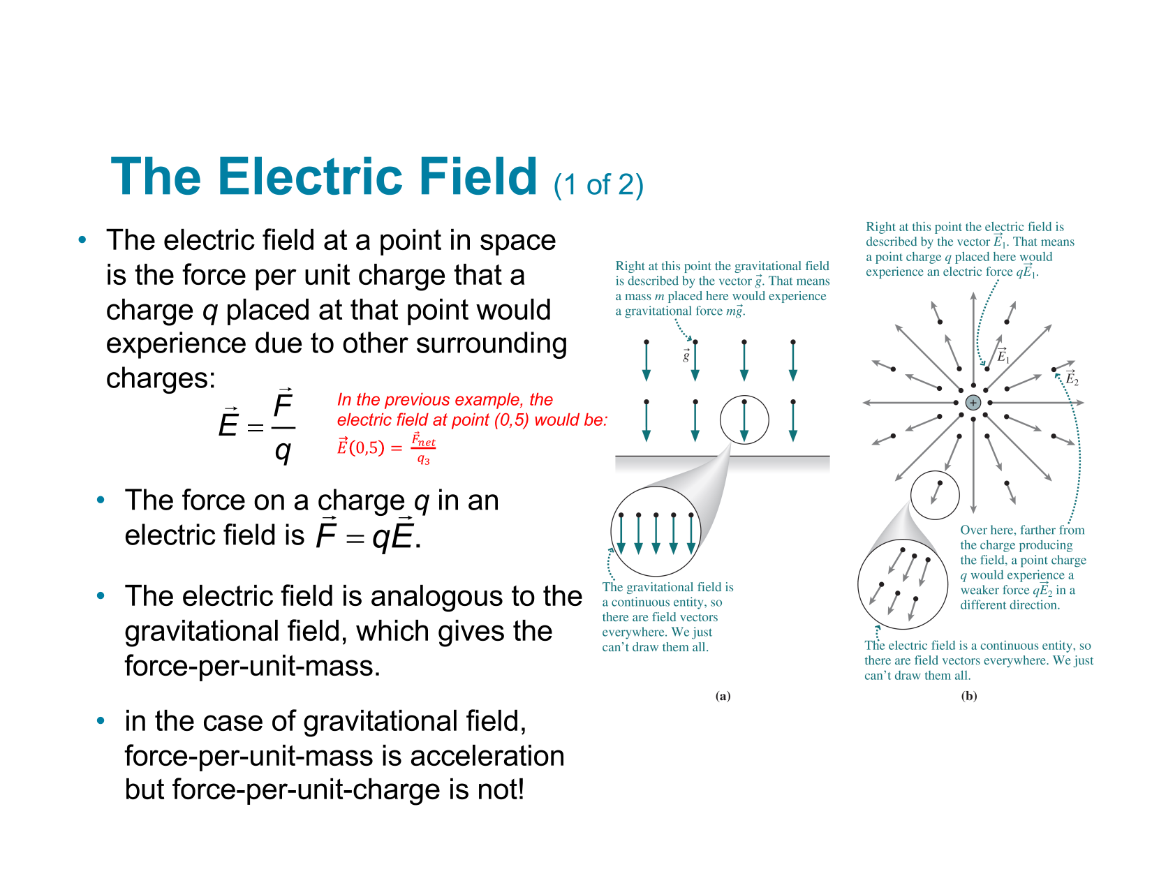
Electric
Fields
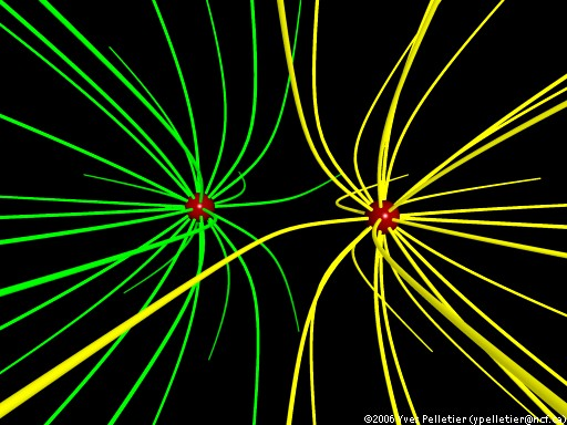
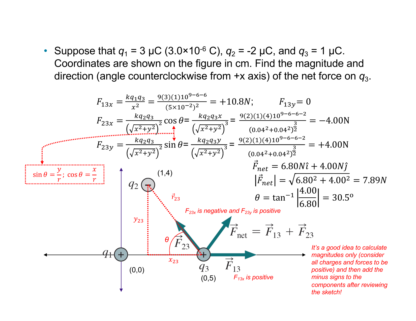
3-D Electric Field Caused by two identical Point Charges
- interaction is described in terms of
Electric
Forces
Charged Particles
The influence
and interactions
of
Today's story...
moving
3-D Electric Field Caused by two identical Point Charges
Biot-Savart Law
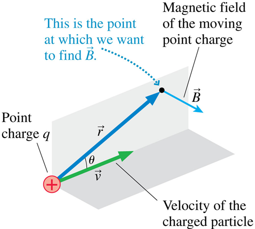
\vec{B}=\frac{\mu_0}{4\pi}\frac{q\ \vec{v}\ \times \ \hat{r}}{r^2}

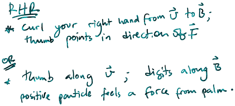
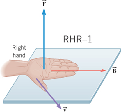
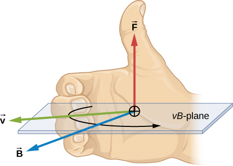
Direction is given by
Right-Hand-Rule
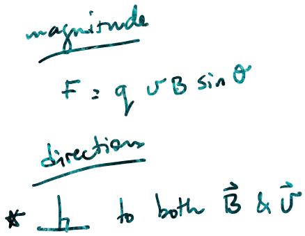
Magnitude is given by
{B}=\frac{\mu_0}{4\pi}\frac{q\ v\ \text{sin}\theta }{r^2}
\mu_0=4\pi\times 10^{-7} T\ m/A
[B]=\text{T for Tesla}
Biot-Savart Law
\vec{B}=\frac{\mu_0}{4\pi}\frac{q\ \vec{v}\ \times \ \hat{r}}{r^2}
Direction is given by
Right-Hand-Rule
Magnitude is given by
{B}=\frac{\mu_0}{4\pi}\frac{q\ v\ \text{sin}\theta }{r^2}
\mu_0=4\pi\times 10^{-7} T\ m/A
[B]=\text{T for Tesla}
Biot-Savart Law
\vec{B}=\frac{\mu_0}{4\pi}\frac{q\ \vec{v}\ \times \ \hat{r}}{r^2}
•Sources are moving charges
–If velocity is zero, magnetic field is zero!
–
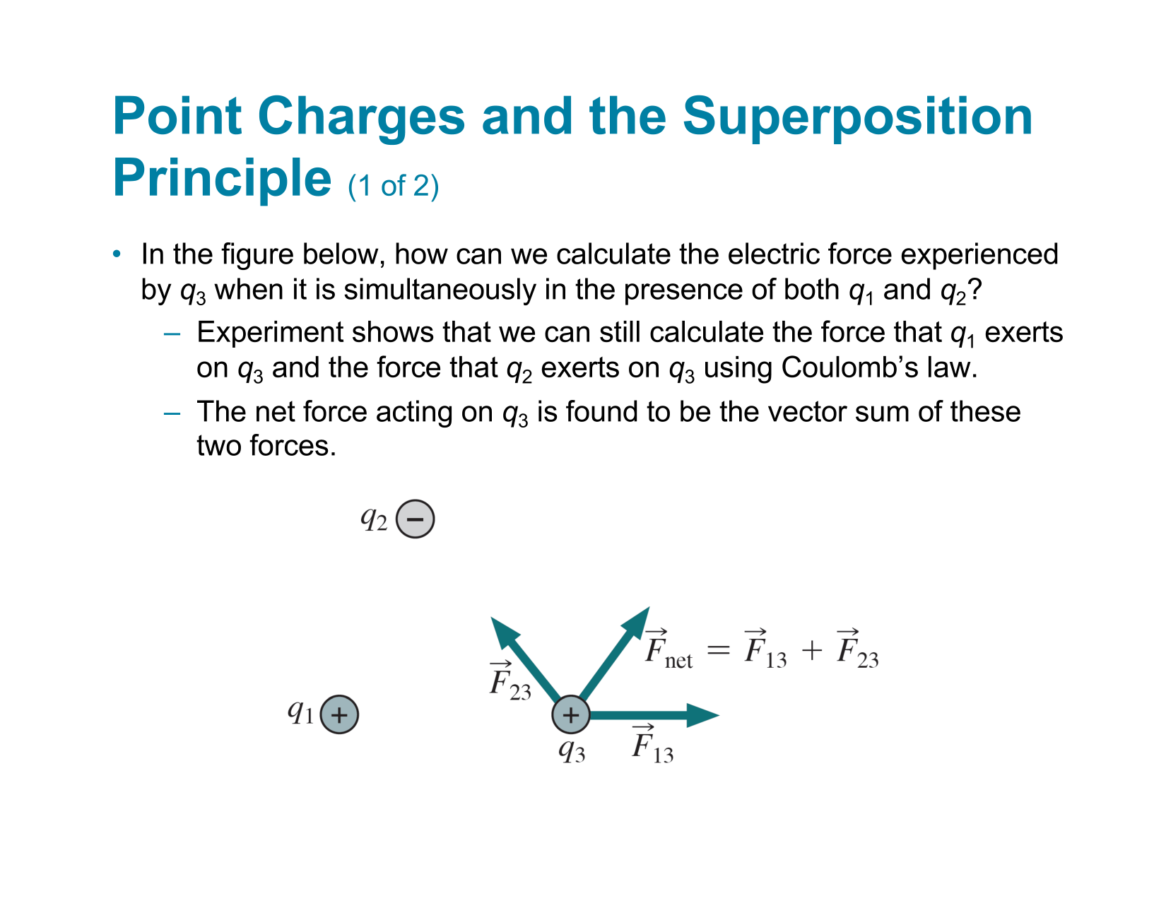
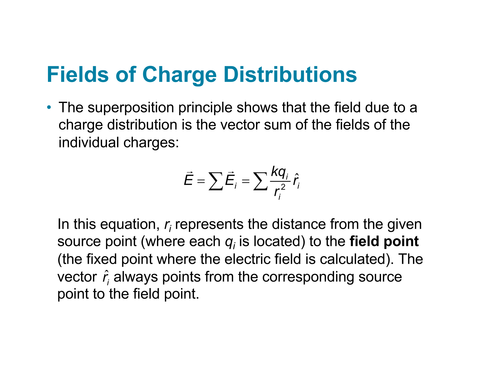
•Superposition principle applies
–Just like electric fields, magnetic field vectors add linearly!
–
•Biot-Savart Law
–Magnetic field strength has inverse square dependence on the distance from the moving charge
Important Highlights
Biot-Savart Law
\vec{B}=\frac{\mu_0}{4\pi}\frac{q\ \vec{v}\ \times \ \hat{r}}{r^2}
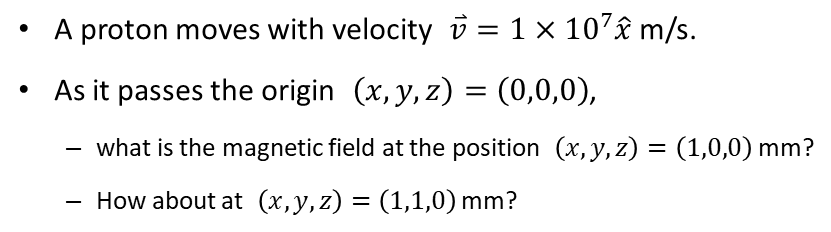
Example
Biot-Savart Law
d\vec{B}=\frac{\mu_0}{4\pi}\frac{I\ d\vec{l}\ \times \ \hat{r}}{r^2}
Magnetic Field due to a Current Segment
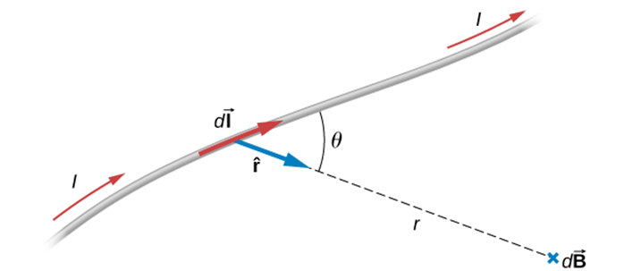
d\vec{B}=\frac{\mu_0}{4\pi}\frac{I\ d\vec{l}\ \times \ \hat{r}}{r^2}
\vec{B}=\frac{\mu_0}{4\pi}\frac{q\ \vec{v}\ \times \ \hat{r}}{r^2}
q \vec{v} = q \frac{d\vec{l}}{dt} = I\ d\vec{l}
Biot-Savart Law
d\vec{B}=\frac{\mu_0}{4\pi}\frac{I\ d\vec{l}\ \times \ \hat{r}}{r^2}
Magnetic Field due to a Current Segment
Magnetic Forces
Magnetic Forces
\vec{F}=q\ \vec{v}\ \times\ \vec{B}
A charge q moving with velocity v relative to a magnetic field B will experience a magnetic force F given by:
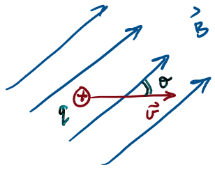
Force on a charge moving relative to a magnetic field
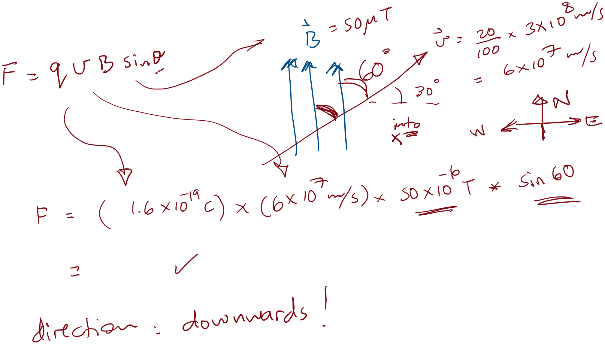
Eg. electron in Earth's field
An electron travelling at 20% the speed of light in a direction 30 degrees North of East, passes through a region where Earth’s magnetic field is uniform, pointing North, with a magnitude of 50 µT. What is (the magnitude and direction of) the magnetic force experienced by the electron?
The electric force
is parallel to
the electric field
The magnetic force
is perpendicular to
the magnetic field
\vec{F}=q\ \vec{v}\ \times\ \vec{B}
\vec{F}=q\ \vec{E}
Electromagnetic Forces
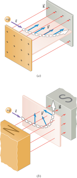
Application: Velocity Selector
A velocity selector is a device that allows charged particles with a particular velocity to pass through, while deflecting all other charged particles.
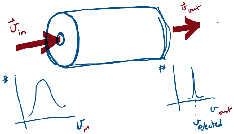
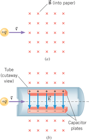
The device operates by applying electric and magnetic forces to the particle in such a way that these
forces balance.
For the situation shown in the figure, how should an electric field be applied so that the force it applies to the particle can balance the magnetic force?
For the situation shown in the figure, what is the selected velocity?
Application: Velocity Selector
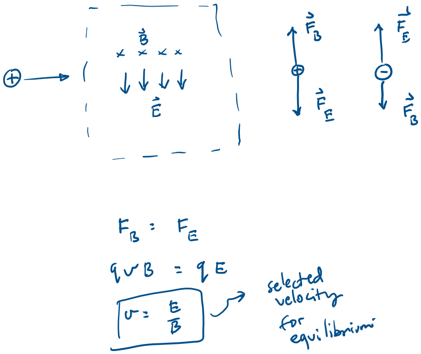
Application: Velocity Selector
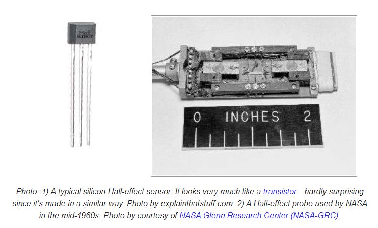
Application: Hall Effect Sensors
The electric force
is not perpendicular to
the motion
The magnetic force
is perpendicular to
the motion
W_\text{magnetic force} = 0
W_\text{electric force}\neq 0
particle speeds up or slows down
particle changes direction of motion
Work by Electromagnetic Forces
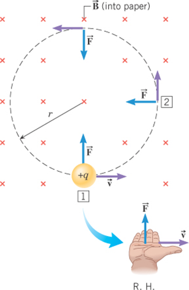
The magnetic force remains
perpendicular to the velocity and is
directed toward the center of the
circular path.
F_c = m\ \frac{v^2}{r}
q\ v\ B= m\ \frac{v^2}{r}
r= \frac{m\ v}{q\ B}
Uniform Circular Motion
m and q are intrinsic quantities
v is the speed (related to KE)
B is the magnetic flux density
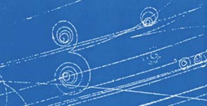
Application
Charged
Particles
in
Cloud/Bubble
Chambers
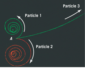
If the magnetic field is directed out of the "page"--
What are the signs of the charges of the three particles?
All 3 particles have the same mass and (magnitude of) charge--
which particle is initially moving most rapidly?
All 3 particles follow a spiraling path --
Are we able to explain why?
The tracks going counter clockwise are left by negatively charged particles.
The bigger the speed, the bigger the radius (for same q, m and B)
Loss of energy (signified by loss of speed, leads to ever decreasing radius)
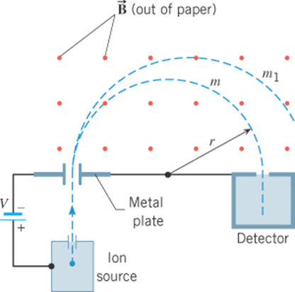
The mass-spectrometer
r= \frac{m\ v}{q\ B}
For fixed v, q, and B
r \propto m
Detector
particle injection
The Mass-Spectrometer
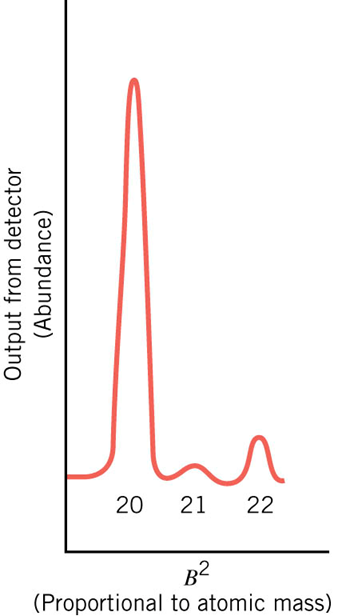
\tfrac{1}{2}mv^2=qV
r= \frac{m\ v}{q\ B}
\}
m=\left(\frac{q\ r^2}{2\ V}\right)\ B^2
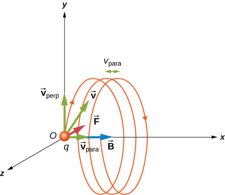
- The velocity component perpendicular to the magnetic field creates circular motion,
- The component of the velocity parallel to the field moves the particle along a straight line.
- The resulting motion is helical.
A charged particle
moving with a velocity
neither parallel nor perpendicular
to the magnetic field.

Force on a current-carrying wire
\vec{F}=\int I\ d\vec{l}\ \times\ \vec{B}
The magnetic forces on the confined charges add up, and manifest as a force on the current carrying wire.
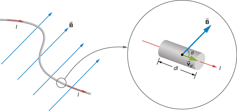
Force on a current-carrying wire
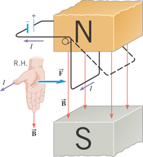
F= I\ L\ B \sin\theta
For a straight segment in a uniform magnetic field:
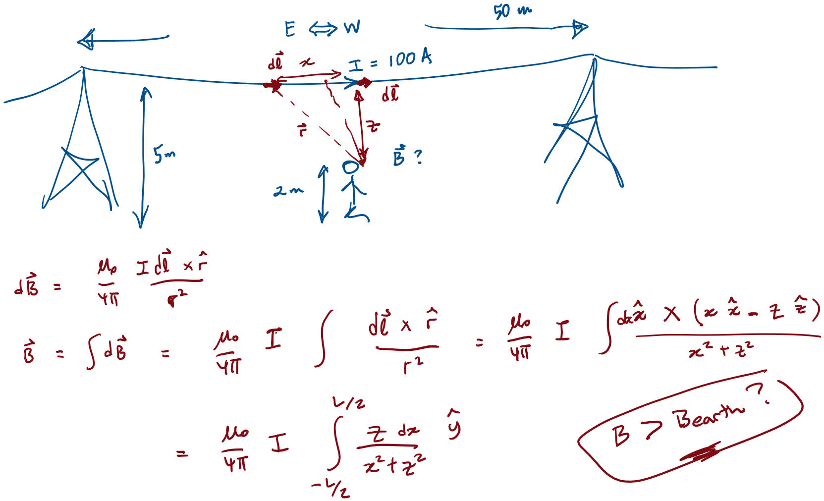
Force on a current-carrying wire
Example: Force on a cable due to Earth's field
Calculate the force per unit length on a power cable carrying 200 A directed eastwards, due to Earth's magnetic field at a location where Earth's field is 50uT pointing North. Is this force a reason for concern?
Force on a current-carrying wire
Example - force between parallel conductors:
Calculate the force per unit length between two cables running parallel to each other, carrying currents of 1.0A and 2.0 A in opposite directions.
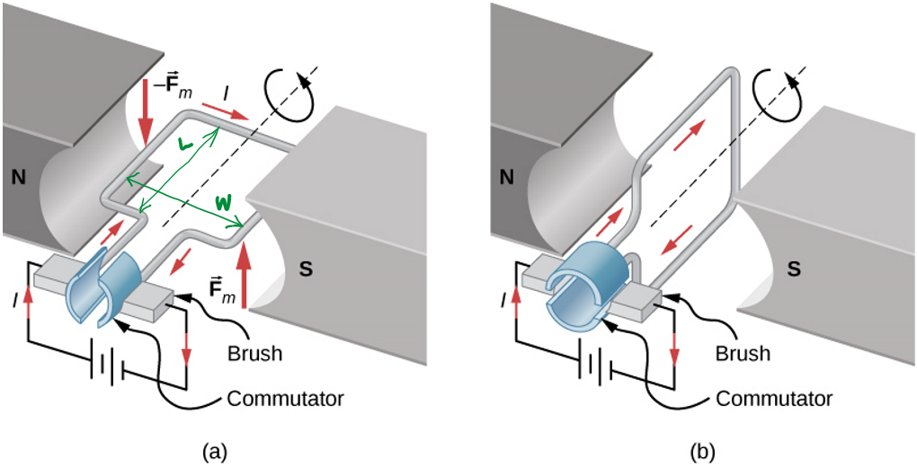
Torque on a current-carrying loop
Consider a rectangular loop, L x W, carrying a current I, in a uniform magnetic field of strength B
F= I\ L\ B \sin\theta
The magnitude of the force on each arm of the loop is given by
These forces are in opposite directions, as given by the RHR
\implies \Sigma\vec{F} =0\quad \&\quad \Sigma\vec{\tau} \ne0
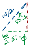
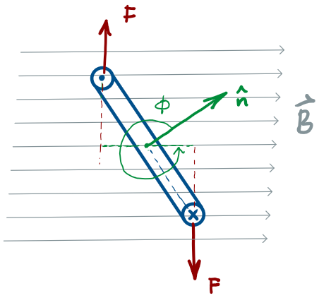
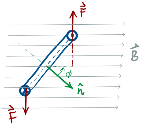
Torque on a current-carrying loop
\Sigma\vec{\tau}=2\times F\times (\frac{W}{2}\sin\phi)
=(ILB\sin\theta) (W\sin\phi)
=IAB\sin\phi
\vec{\tau}=\vec{\mu}\times\vec{B}
\vec{\mu}=IA\ \hat{n}
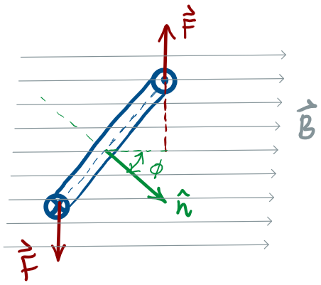
To calculate the net torque about the axis of rotation, consider the situation where the normal to the loop makes an angle with the magnetic field:
\phi
where
\implies
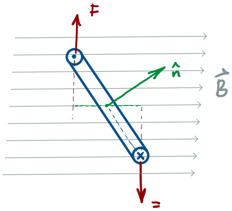
Torque on a current-carrying loop
Notice that the torque follows the sin function
\vec{\tau}=\vec{\mu}\times\vec{B}
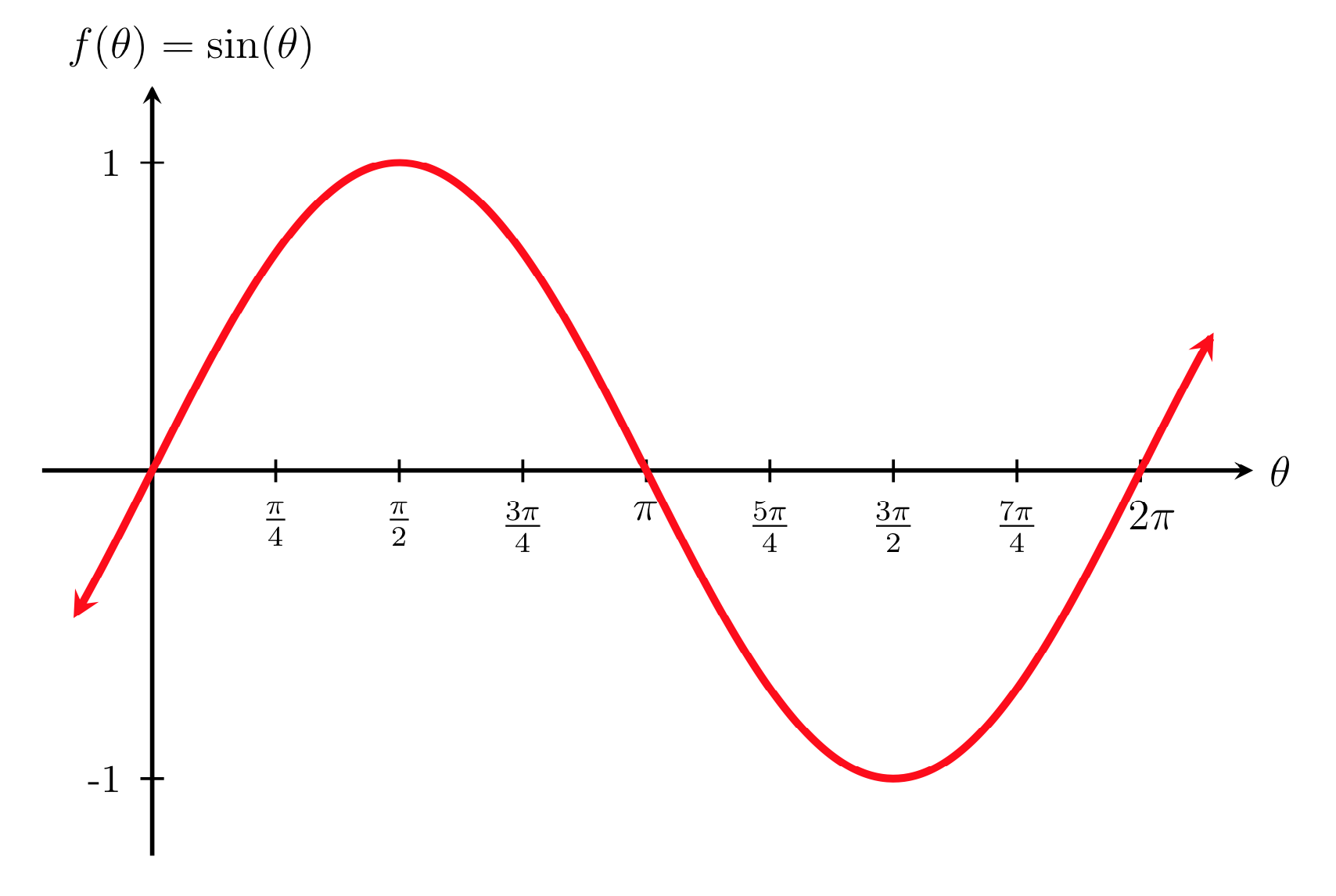
The torque on a current loop is a restoring torque!
(i.e. tends to align the normal to the loop with the field!)
no torque when
\implies
\hat{n}\ \parallel \vec{B}
\implies
Torque on a current-carrying loop

If you want to generate rotational motion, Opposite
Torques is a problem!
(Genius)
Solution:
Brush!


RC-Circuits
By omoussa


