Magnetic Forces
Magnetic Forces
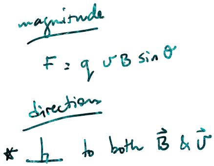
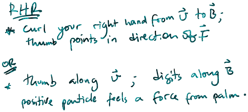
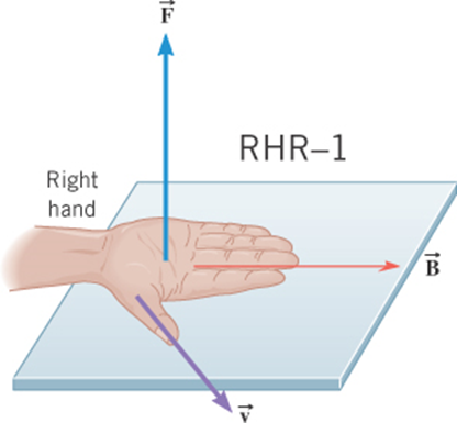
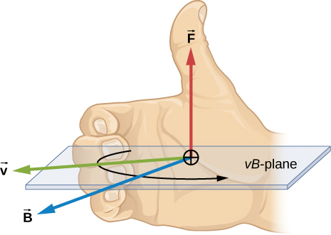
\vec{F}=q\ \vec{v}\ \times\ \vec{B}
A charge q moving with velocity v relative to a magnetic field B will experience a magnetic force F given by:
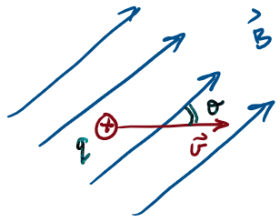
Force on a charge moving relative to a magnetic field
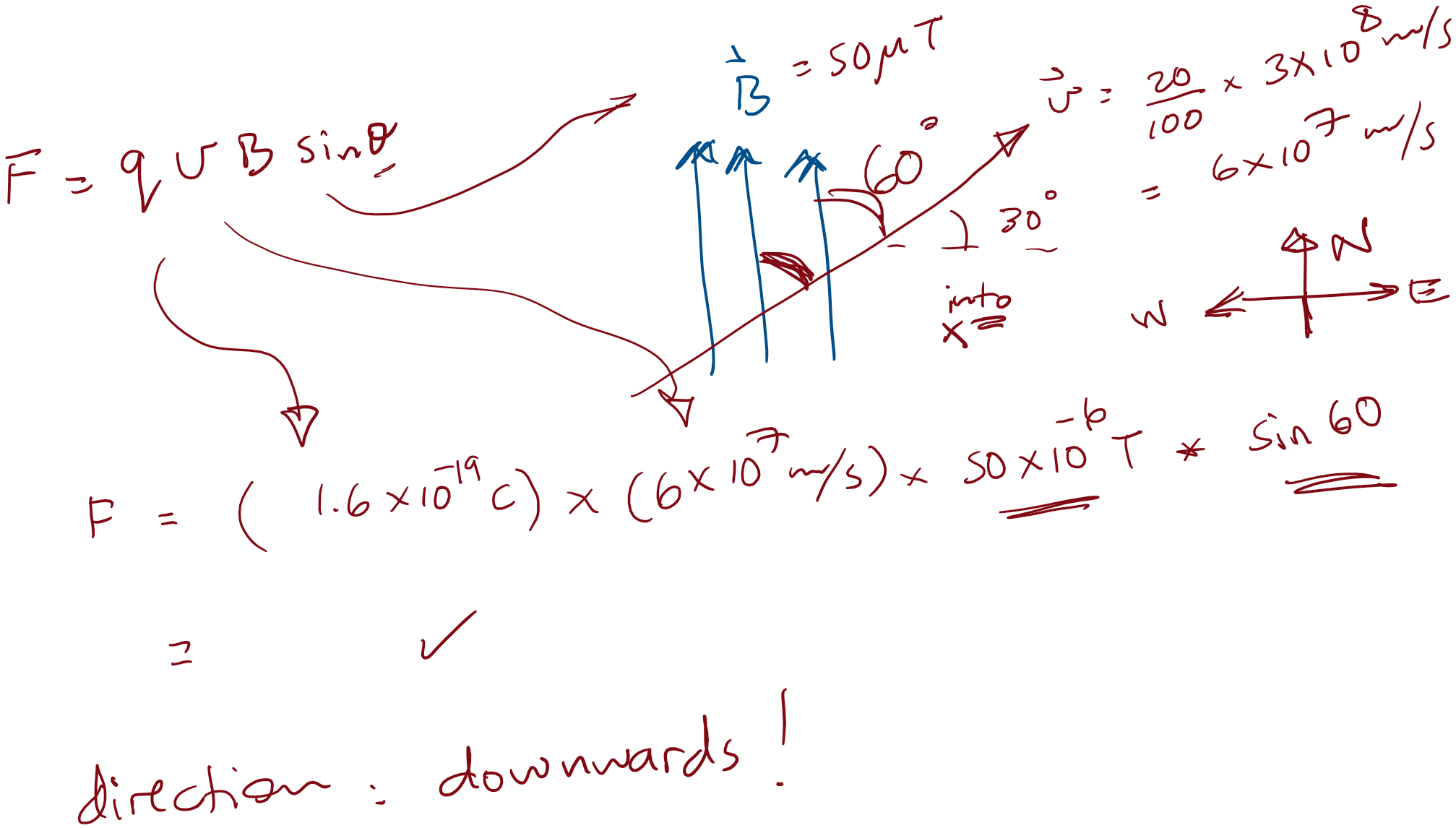
Eg. electron in Earth's field
An electron travelling at 20% the speed of light in a direction 30 degrees North of East, passes through a region where Earth’s magnetic field is uniform, pointing North, with a magnitude of 50 µT. What is (the magnitude and direction of) the magnetic force experienced by the electron?
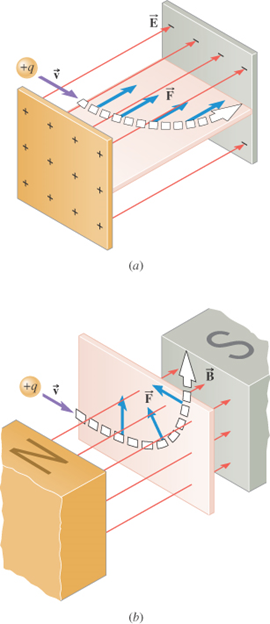
The electric force
is parallel to
the electric field
The magnetic force
is perpendicular to
the magnetic field
\vec{F}=q\ \vec{v}\ \times\ \vec{B}
\vec{F}=q\ \vec{E}
Electromagnetic Forces
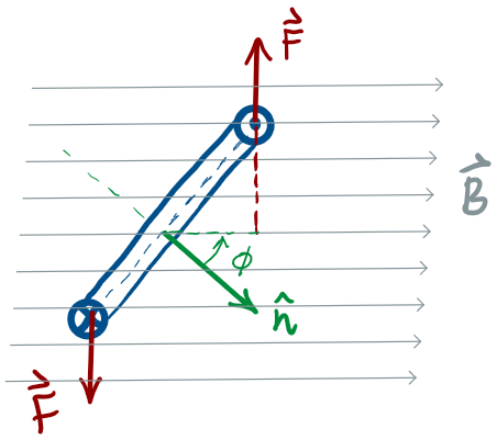
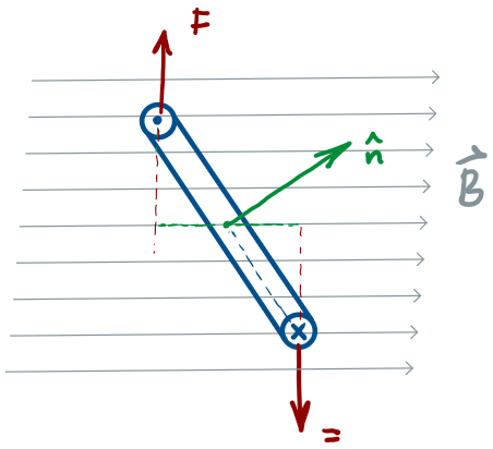
Application: Velocity Selector
A velocity selector is a device that allows charged particles with a particular velocity to pass through, while deflecting all other charged particles.
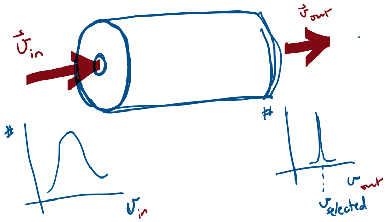
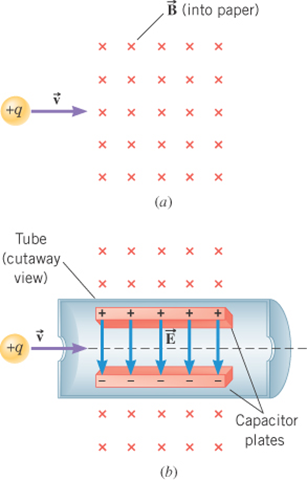
The device operates by applying electric and magnetic forces to the particle in such a way that these
forces balance.
For the situation shown in the figure, how should an electric field be applied so that the force it applies to the particle can balance the magnetic force?
For the situation shown in the figure, what is the selected velocity?
Application: Velocity Selector
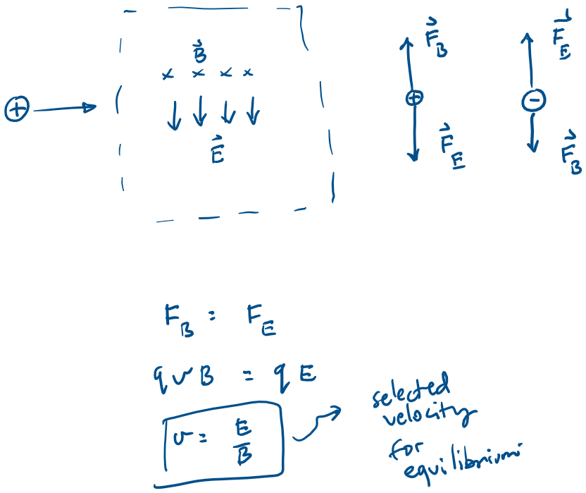
Application: Velocity Selector
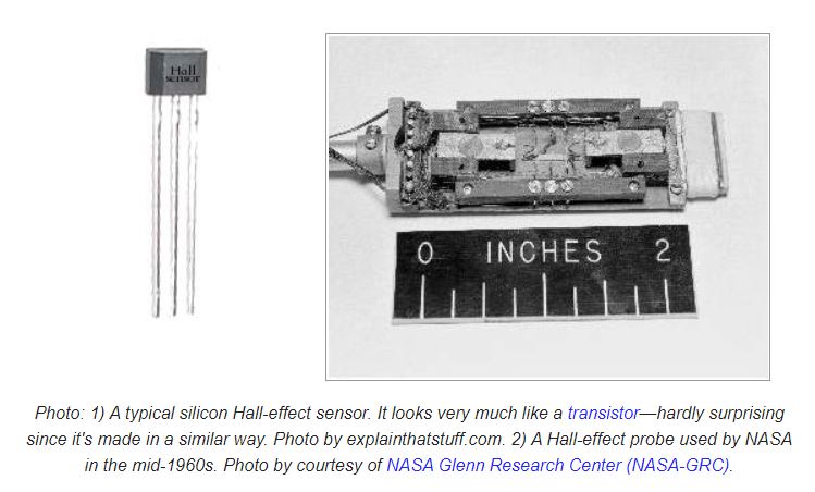
Application: Hall Effect Sensors
The electric force
is not perpendicular to
the motion
The magnetic force
is perpendicular to
the motion
W_\text{magnetic force} = 0
W_\text{electric force}\neq 0
particle speeds up or slows down
particle changes direction of motion
Work by Electromagnetic Forces
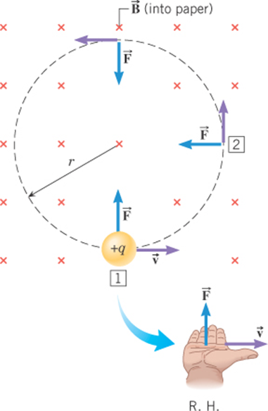
The magnetic force remains
perpendicular to the velocity and is
directed toward the center of the
circular path.
F_c = m\ \frac{v^2}{r}
q\ v\ B= m\ \frac{v^2}{r}
r= \frac{m\ v}{q\ B}
Uniform Circular Motion
m and q are intrinsic quantities
v is the speed (related to KE)
B is the magnetic flux density
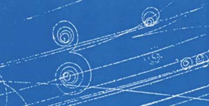
Application
Charged
Particles
in
Cloud/Bubble
Chambers
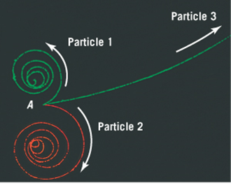
If the magnetic field is directed out of the "page"--
What are the signs of the charges of the three particles?
All 3 particles have the same mass and (magnitude of) charge--
which particle is initially moving most rapidly?
All 3 particles follow a spiraling path --
Are we able to explain why?
The tracks going counter clockwise are left by negatively charged particles.
The bigger the speed, the bigger the radius (for same q, m and B)
Loss of energy (signified by loss of speed, leads to ever decreasing radius)
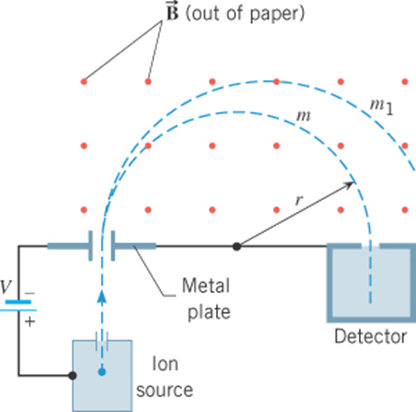
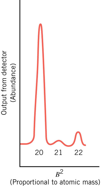
The mass-spectrometer
r= \frac{m\ v}{q\ B}
For fixed v, q, and B
r \propto m
Detector
particle injection
The Mass-Spectrometer
\tfrac{1}{2}mv^2=qV
r= \frac{m\ v}{q\ B}
\}
m=\left(\frac{q\ r^2}{2\ V}\right)\ B^2
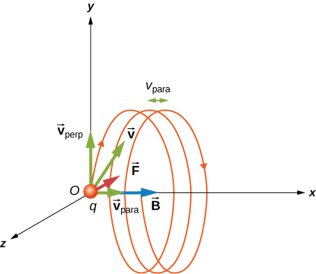
- The velocity component perpendicular to the magnetic field creates circular motion,
- The component of the velocity parallel to the field moves the particle along a straight line.
- The resulting motion is helical.
A charged particle
moving with a velocity
neither parallel nor perpendicular
to the magnetic field.

Force on a current-carrying wire
\vec{F}=\int I\ d\vec{l}\ \times\ \vec{B}
The magnetic forces on the confined charges add up, and manifest as a force on the current carrying wire.
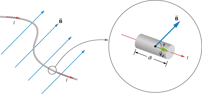
Force on a current-carrying wire
F= I\ L\ B \sin\theta
For a straight segment in a uniform magnetic field:
Force on a current-carrying wire
Example: Force on a cable due to Earth's field
Calculate the force per unit length on a power cable carrying 200 A directed eastwards, due to Earth's magnetic field at a location where Earth's field is 50uT pointing North. Is this force a reason for concern?
Force on a current-carrying wire
Example - force between parallel conductors:
Calculate the force per unit length between two cables running parallel to each other, carrying currents of 1.0A and 2.0 A in opposite directions.
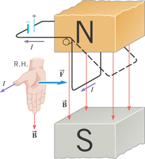
Torque on a current-carrying loop
Consider a rectangular loop, L x W, carrying a current I, in a uniform magnetic field of strength B
F= I\ L\ B \sin\theta
The magnitude of the force on each arm of the loop is given by
These forces are in opposite directions, as given by the RHR
\implies \Sigma\vec{F} =0\quad \&\quad \Sigma\vec{\tau} \ne0
Torque on a current-carrying loop
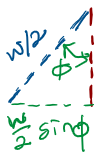
\Sigma\vec{\tau}=2\times F\times (\frac{W}{2}\sin\phi)
=(ILB\sin\theta) (W\sin\phi)
=IAB\sin\phi
\vec{\tau}=\vec{\mu}\times\vec{B}
\vec{\mu}=IA\ \hat{n}
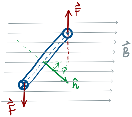
To calculate the net torque about the axis of rotation, consider the situation where the normal to the loop makes an angle with the magnetic field:
\phi
where
\implies
Torque on a current-carrying loop
Notice that the torque follows the sin function
\vec{\tau}=\vec{\mu}\times\vec{B}
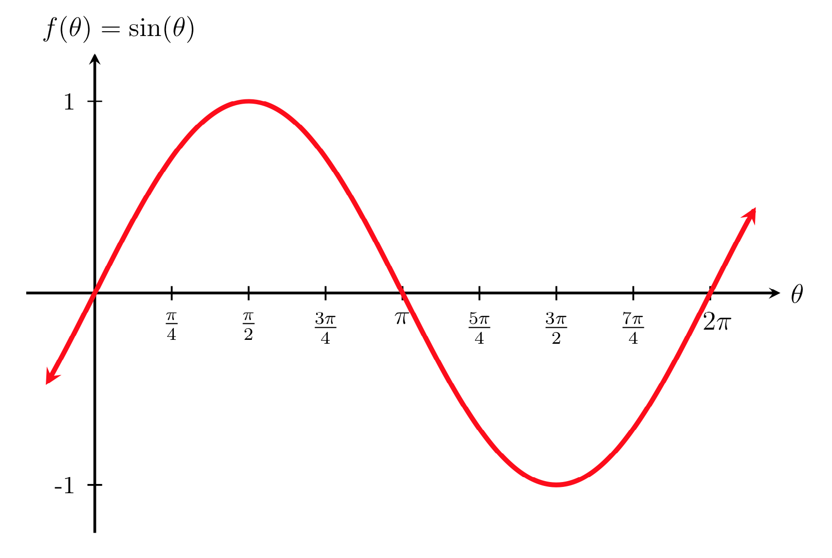
The torque on a current loop is a restoring torque!
(i.e. tends to align the normal to the loop with the field!)
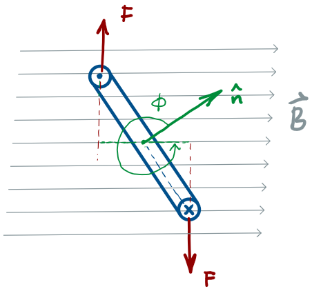
no torque when
\implies
\hat{n}\ \parallel \vec{B}
\implies
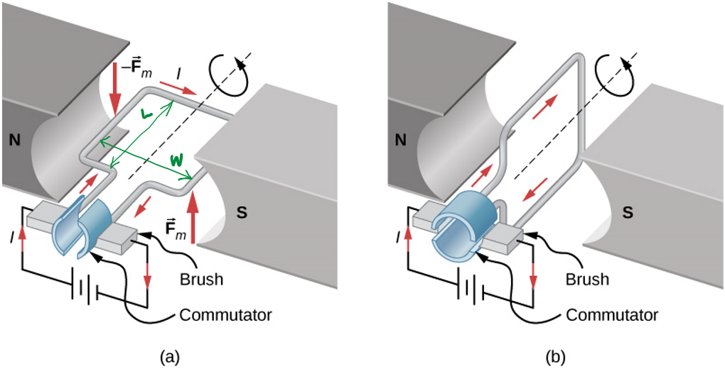
Torque on a current-carrying loop

If you want to generate rotational motion, Opposite
Torques is a problem!
(Genius)
Solution:
Brush!
Magnetic Forces
By omoussa


