Engineering design
W7-1
Professor: Oscar Alonso Rosete Beas
Agenda
-
Unit 2 introduction
- Orthographic Projection
- Multiview drawings
Course outline
| Description | Assigned time | |
|---|---|---|
| Unit 1 | Mechanical drawing | 12 hrs |
| Unit 2 | Orthographic multiview drawings/projections | 24 hrs |
| Unit 3 | Dimensioning | 10 hrs |
| Unit 4 | Isometric projection | 10 hrs |
Portfolio draft (10)
Portfolio draft (11)
A view of an object is called a projection. By projecting multiple views from different directions in a systematic way, you can completely describe the shape of 3D objects.
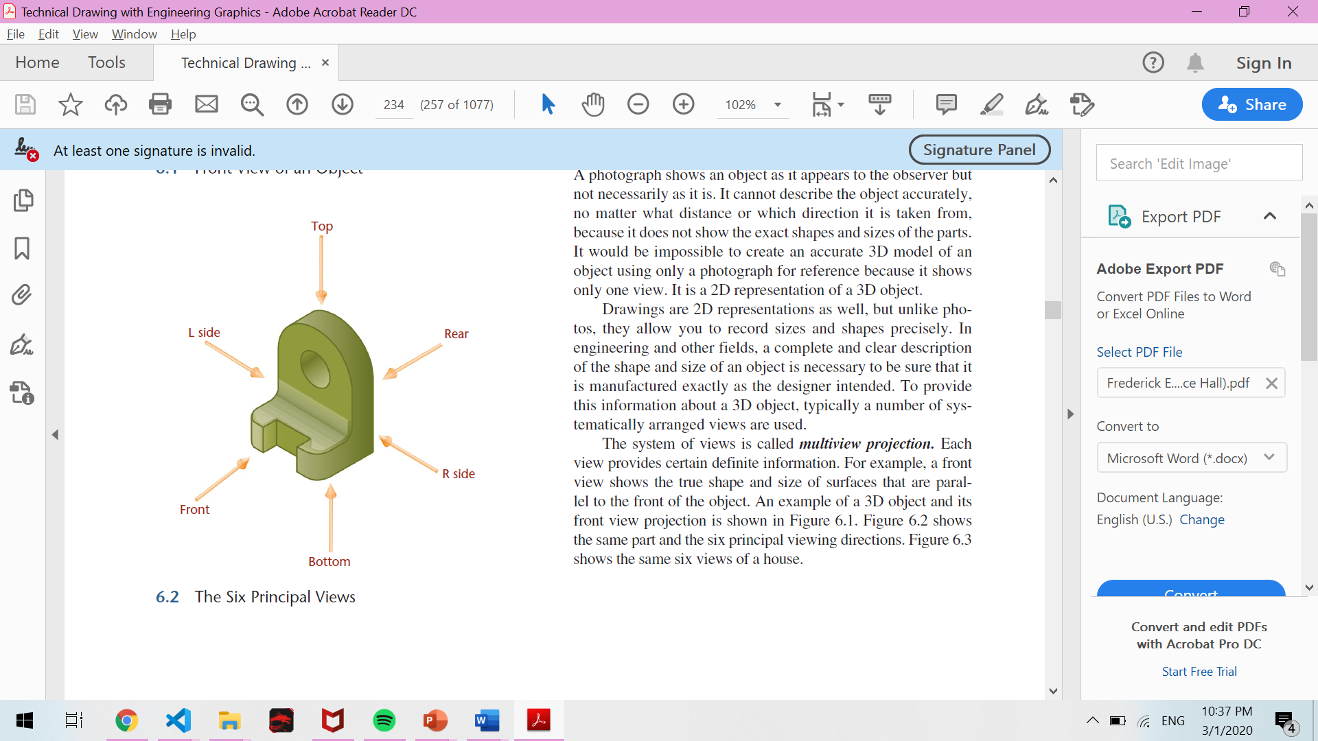
A photograph shows an object as it appears to the observer but not necessarily as it is. It cannot describe the object accurately, no matter what distance or which direction it is taken from, because it does not show the exact shapes and sizes of the parts.
Orthographic Projection
There are certain standard practices that you must know to create sketches and documentation drawings that can be easily interpreted.
To provide information about a 3D object, typically a number of systematically arranged views are used. The system of views is called multiview projection. Each view provides certain information.
Orthographic Projection
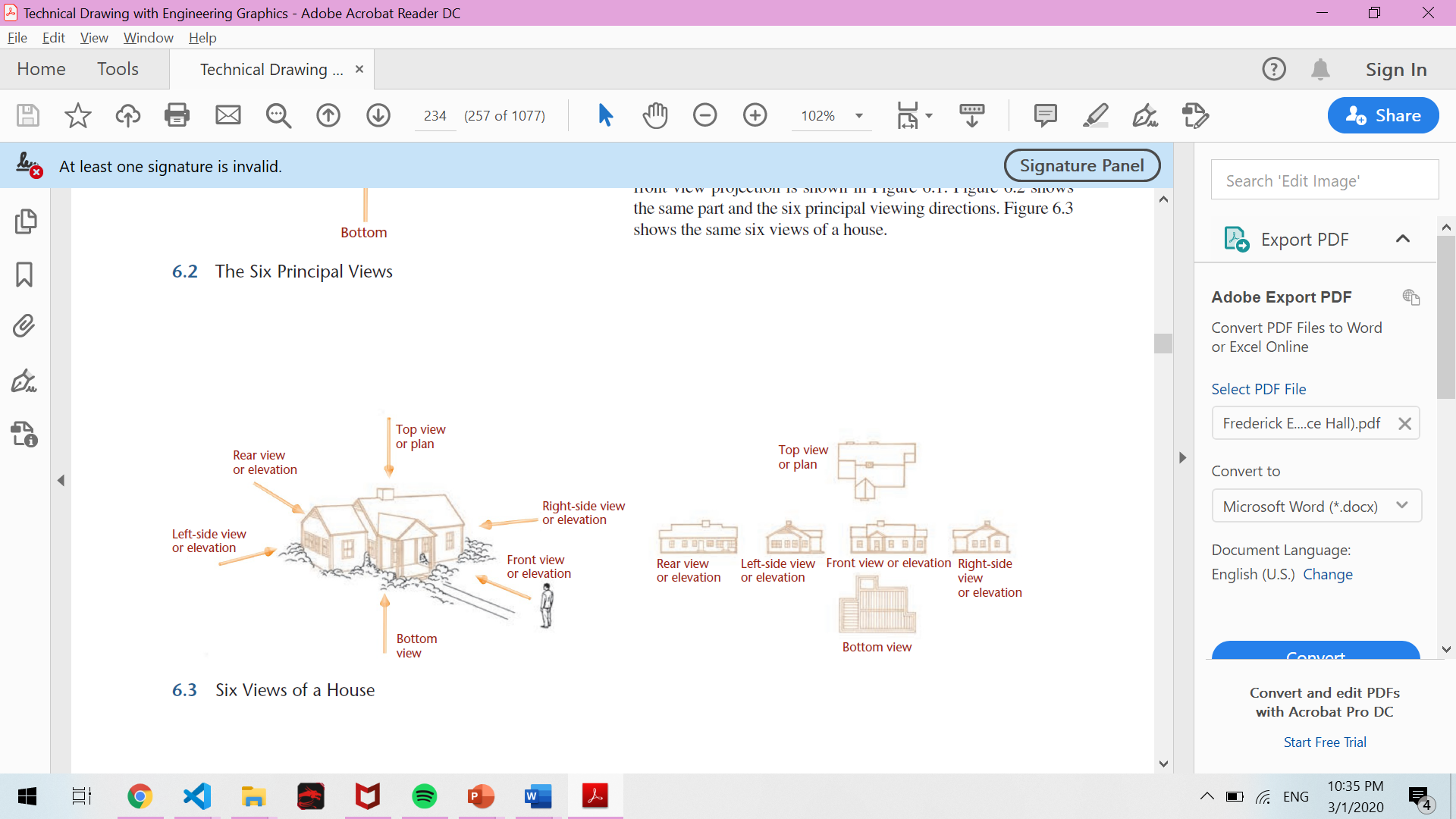
Any object can be viewed from six mutually perpendicular directions, as shown in Figure. These are called the six principal views.
You can think of the six views as what an observer would see by moving around the object.
Orthographic Projection
Principal Dimensions
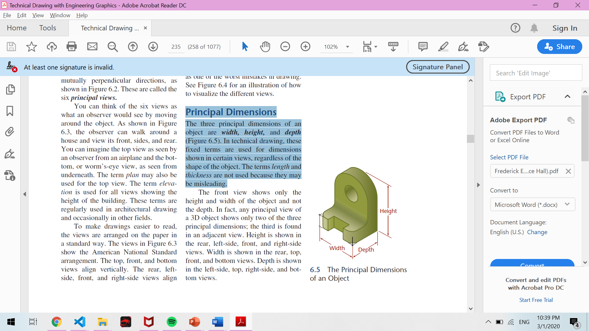
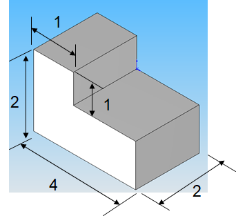
The three principal dimensions of an object are width, height, and depth.
In technical drawing, these fixed terms are used for dimensions shown in certain views, regardless of the shape of the object. The terms length and thickness are not used because they may be misleading.
Orthographic Projection
The Glass Box
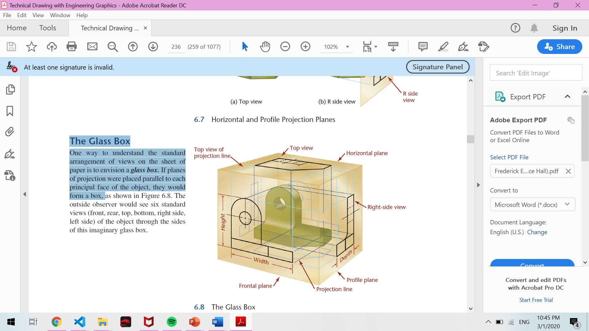
One way to understand the standard arrangement of views on the sheet of paper is to envision a glass box. If planes of projection were placed parallel to each principal face of the object, they would form a box.
Orthographic Projection
Unfolding the Glass Box
Orthographic Projection
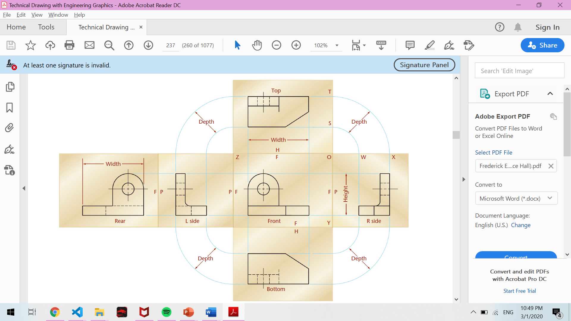
The previous figure shows that any object depicts its principal dimensions in the following manner:
- The front and bottom views show the height and the width, but not the depth.
- Right and left side views show height and depth, but not the width.
- Top and bottom views show width and depth but not the height.
Note that any view shows two dimensions of an object. This implies that any tridimensional object requires at least two views to describe it, and frequently three or more depending on the complexity.
Summary
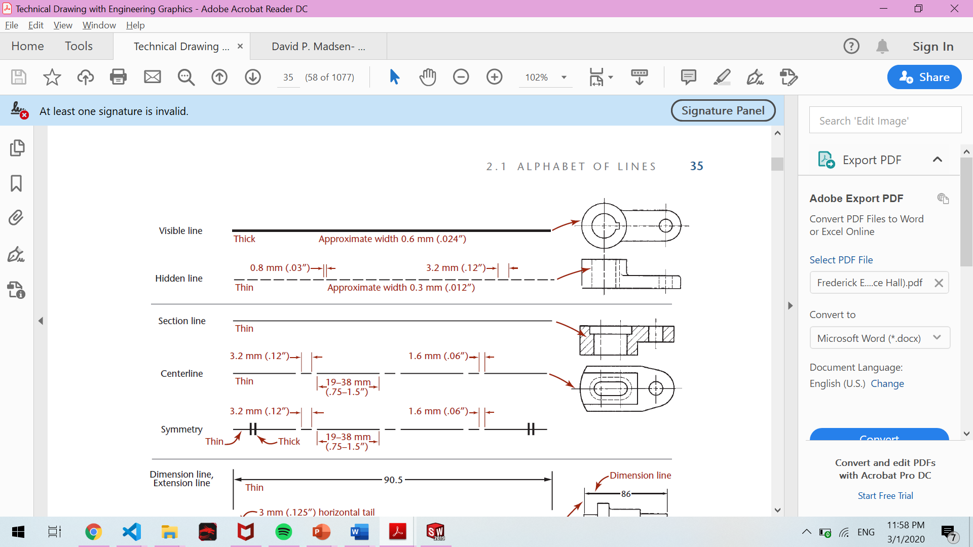
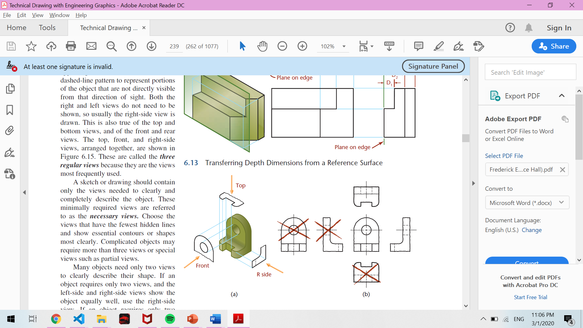
Right and left side views are essentially mirror images of each other, only with different lines appearing hidden. Hidden lines use a dashed-line pattern to represent portions of the object that are not directly visible from that direction of sight.
Necessary views
Both the right and left views do not need to be shown, so usually the right-side view is drawn.
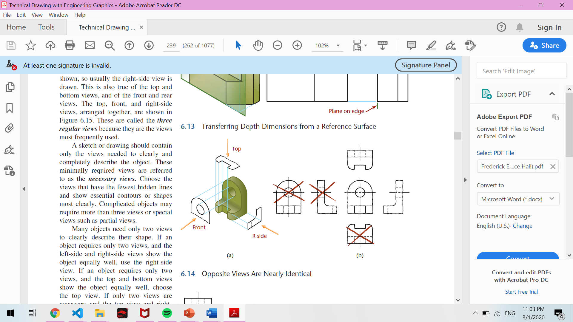
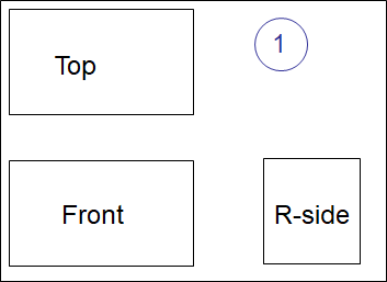
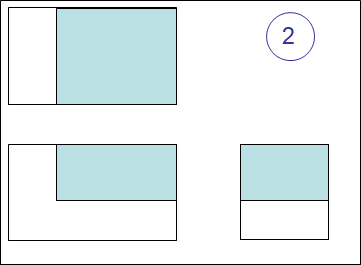
This is also true of the top and bottom views, and of the front and rear views. The top, front, and right-side views, arranged together are called the three regular views because they are the views most frequently used.
Necessary views
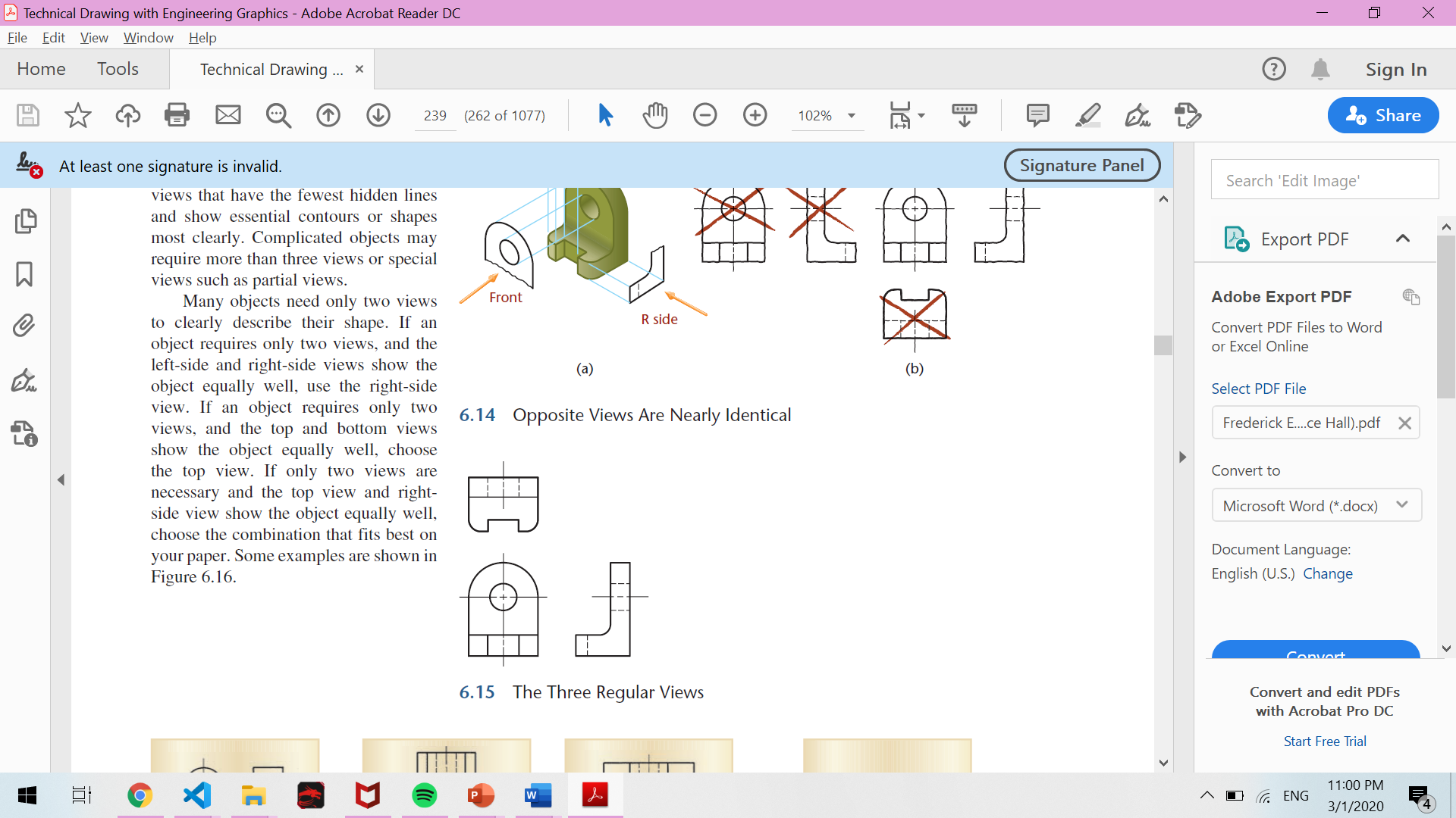
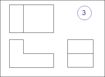
The three regular views
A sketch or drawing should contain only the views needed to clearly and completely describe the object. These minimally required views are referred to as the necessary views.
Choose the views that have the fewest hidden lines and show essential contours or shapes most clearly. Complicated objects may require more than three views or special views such as partial views.
Necessary views
Usually, you should select the front view first. The front view is generally the most important view and, as you learned from the glass box description, it is the origin of all other views. There is no exact way for everyone to select the same front view always, but there are some guidelines to follow. The front view should:
Selecting the Front View
- Represent the most natural position of use.
- Provide the best shape description or most characteristic contours.
- Have the longest dimension.
- Have the fewest hidden features.
- Be the most stable and natural position.
Walkthrough
Frame of 1 cm
Include the title block in the bottom right corner
Title block (ANSI):
-
Name: CETYS, Title: Draft #12, drafted by: your initials, Additional Approval: OARB,Size: A, Drawing Number: 12
-
Include the date in which it was drawn.
Units expressed in cm. Multiply by a factor of 2.
Try to horizontally and vertically center your draft on the remaining blank space.
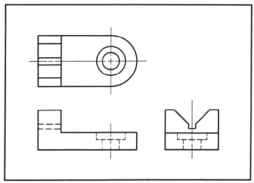
Draw the three regular views of the component as seen on the previous procedure.
Include the annotations
Multiview-drawing
Portfolio draft (12)
Technical Drawing W7-1
By oscaralonso11


