Engineering design
W8-2
Professor: Oscar Alonso Rosete Beas
Agenda
-
Unit 2 introduction
- Orthographic Projection
- Multiview drawings
- Third-angle vs First-angle projection
Portfolio draft (10)
Portfolio draft (11)
Portfolio draft (12)
Portfolio draft (13)
MACHINED FEATURE AND DRAWING
REPRESENTATIONS
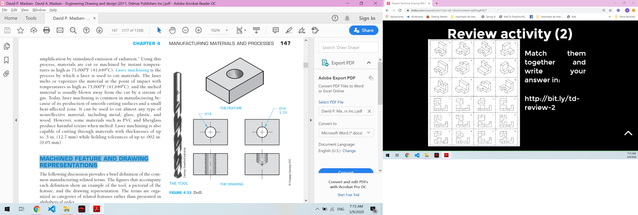
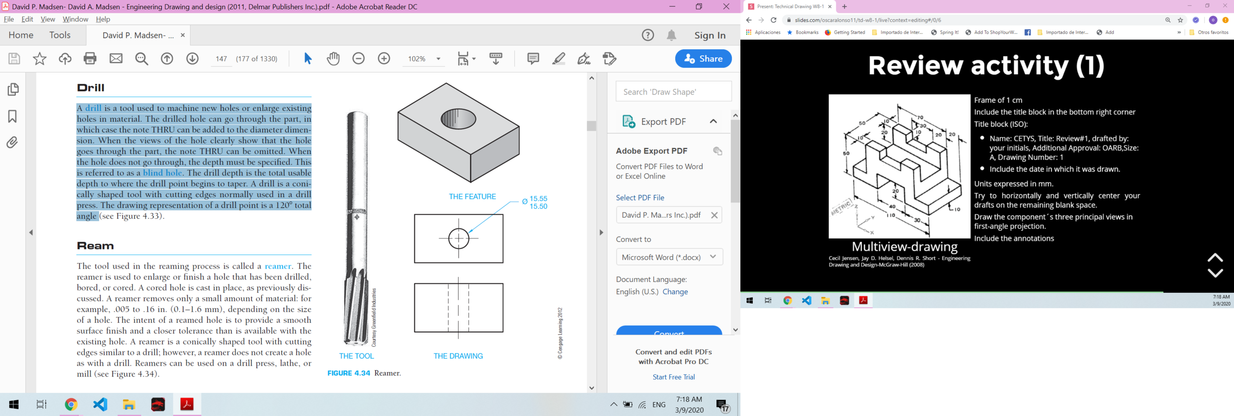
Drill
A drill is a tool used to machine new holes or enlarge existing holes in material. The drilled hole can go through the part, in which case the note THRU can be added to the diameter dimension.
When the views of the hole clearly show that the hole goes through the part, the note THRU can be omitted. When the hole does not go through, the depth must be specified. This is referred to as a blind hole.
MACHINED FEATURE AND DRAWING
REPRESENTATIONS
David P. Madsen- Engineering Drawing and design
Drill
The drill depth is the total usable depth to where the drill point begins to taper. A drill is a conically shaped tool with cutting edges normally used in a drill press.
The drawing representation of a drill point is a 120° total angle.
Drill point
(blind hole)
Centerline
Hidden line
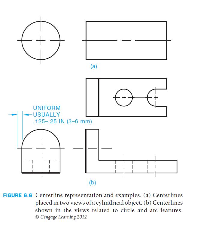
Centerlines
Centerlines are also used to show the centers in a circle pattern or the paths of motion in a mechanism.
Recommendations:
- Half as thick as visible lines for contrast.
- Long dash is about 19–35 mm long.
- Spaces between dashes are about 1.5 mm.
- Short dash about 3 mm long.
- Centerlines should start and end with long dashes and extend uniformly a short distance, such as 3 mm or 6 mm past an object.
David P. Madsen- Engineering Drawing and design
MACHINED FEATURE AND DRAWING
REPRESENTATIONS
David P. Madsen- Engineering Drawing and design
Ream
The reaming process is used to enlarge or finish a hole that has been drilled, bored, or cored.
A reamer is a conically shaped tool with cutting edges similar to a drill; however, a reamer does not create a hole as with a drill. Reamers can be used on a drill press, lathe, or mill. A reamer removes only a small amount of material
MACHINED FEATURE AND DRAWING
REPRESENTATIONS
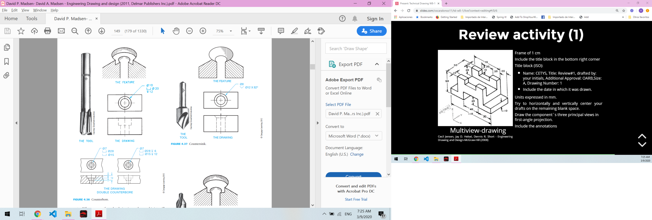
Counterbore
The counterbore is used to enlarge the end(s) of a machined hole to a specified diameter and depth. The machined hole is made first, and then the counterbore is aligned during the machining process by means of a pilot shaft at the end of the tool.
Countersink
A countersink is a conical feature at the end of a machined hole. Countersinks are used to recess the conically shaped head of a fastener such as a flathead machine screw. The drafter should specify the countersink note so that the fastener head is recessed slightly below the surface.
MACHINED FEATURE AND DRAWING
REPRESENTATIONS

David P. Madsen- Engineering Drawing and design
MACHINED FEATURE AND DRAWING
REPRESENTATIONS
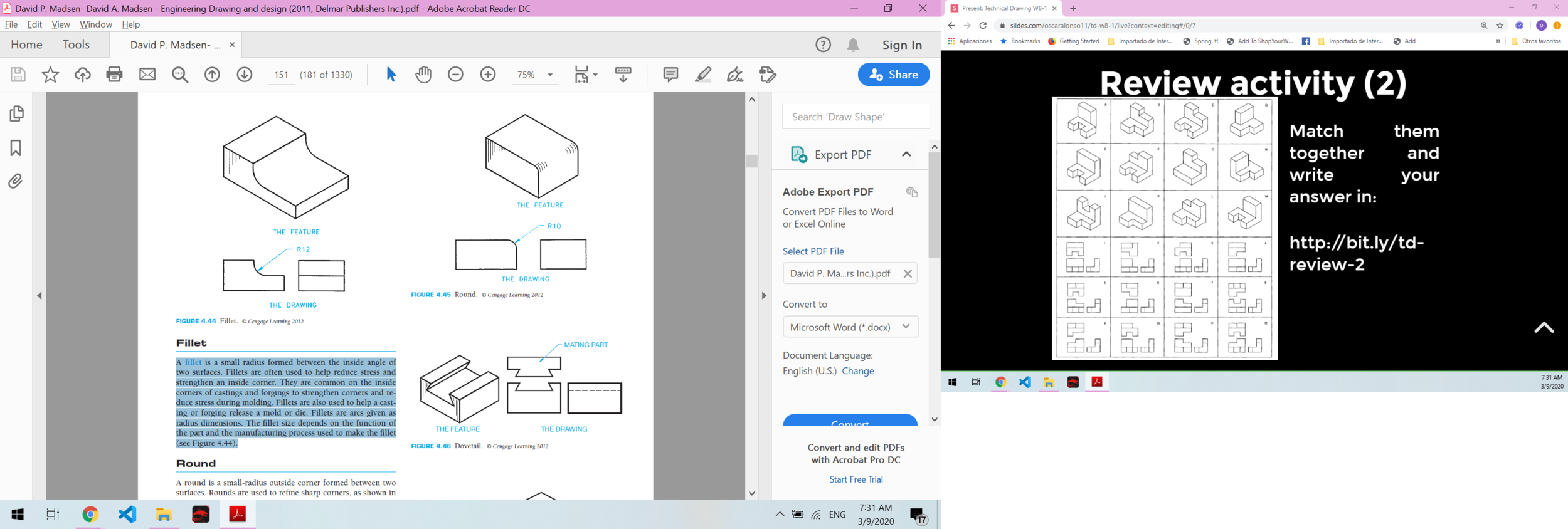
Round
A round is a small-radius outside corner formed between two surfaces. Rounds are used to refine sharp corners.
David P. Madsen- Engineering Drawing and design
Summary video
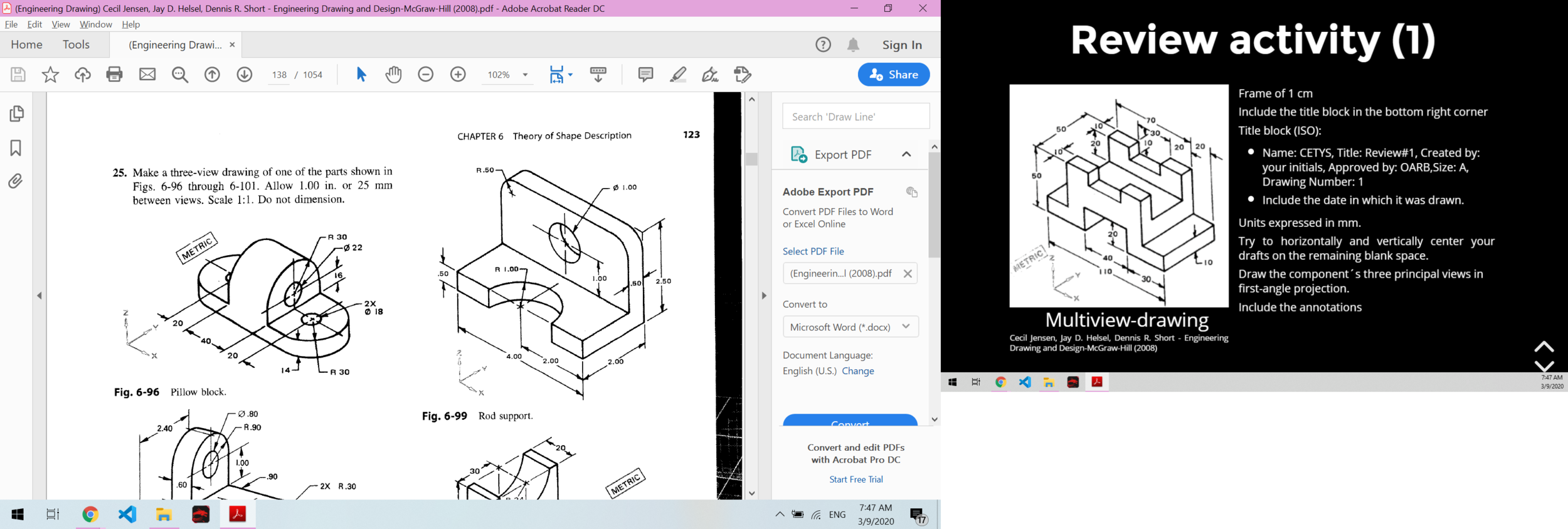
Frame of 1 cm
Include the title block in the bottom right corner
Title block (ANSI):
-
Name: CETYS, Title: Draft #14, drafted by: your initials, Additional Approval: OARB,Size: A, Drawing Number: 14
-
Include the date in which it was drawn.
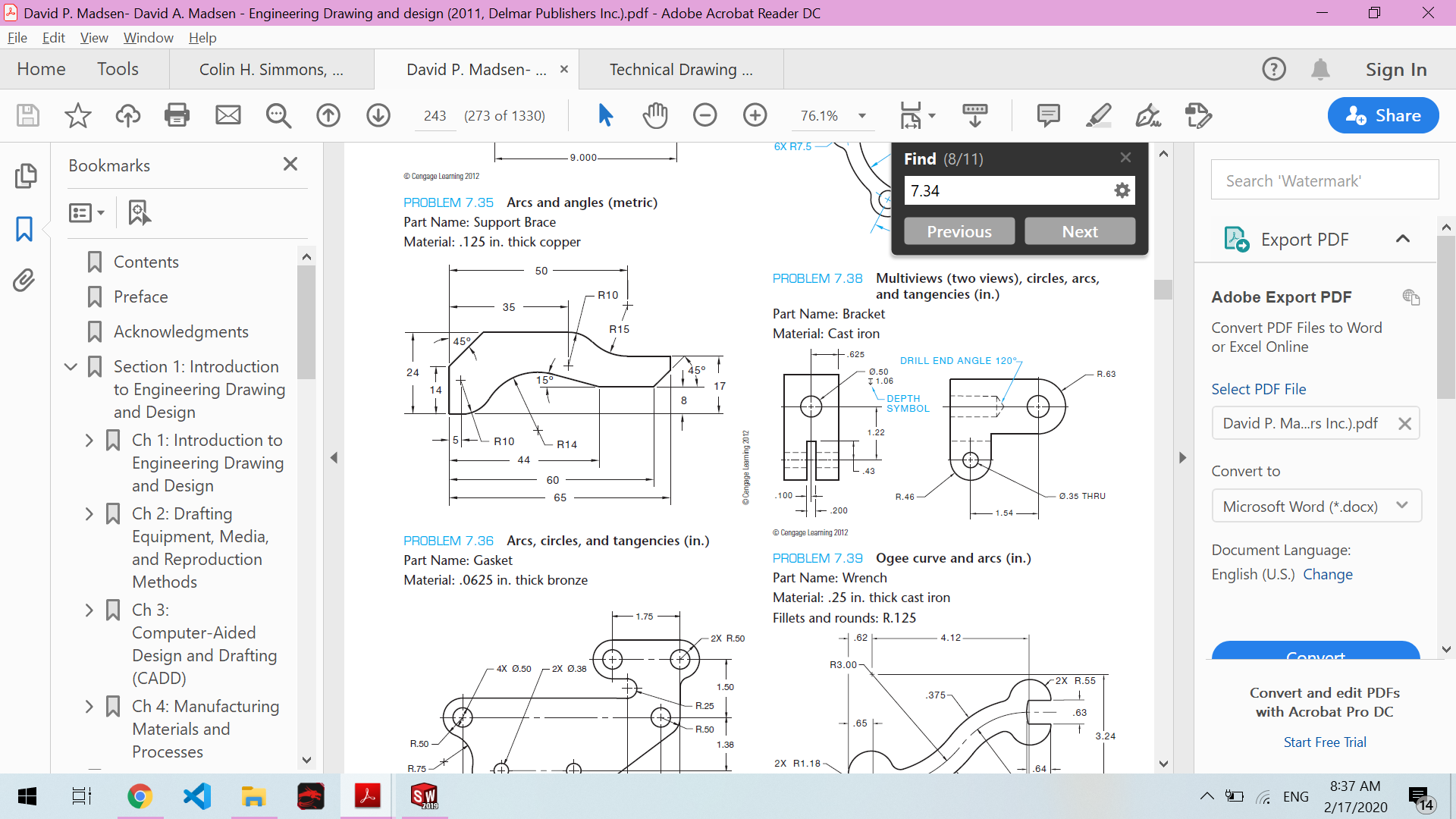
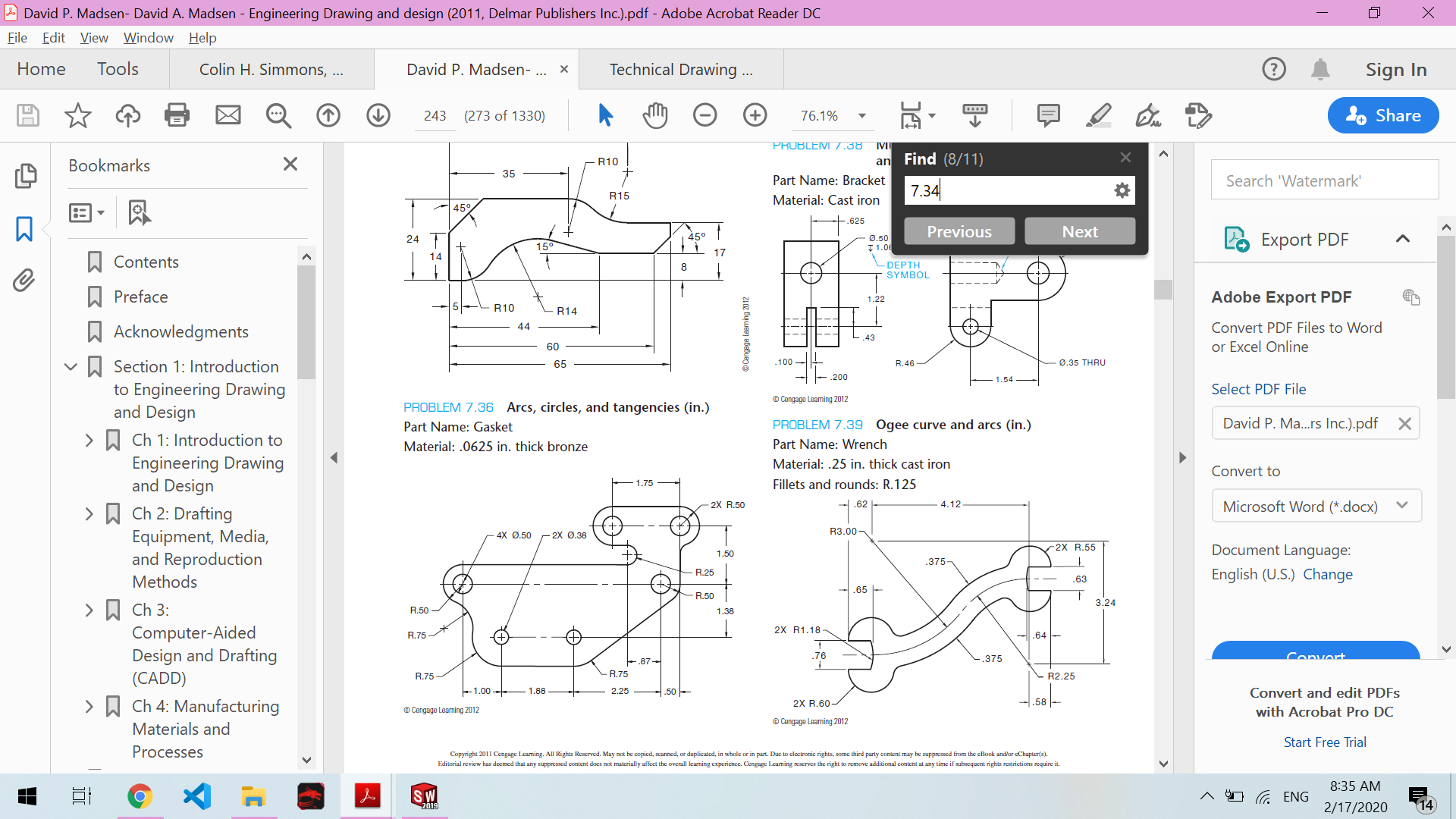
Units expressed in inches.
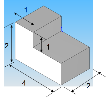
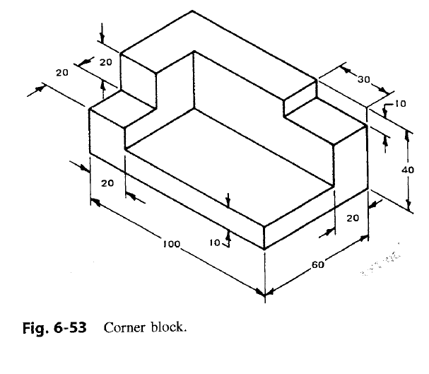
Draw the component´s three principal views in third-angle projection.
Try to horizontally and vertically center your drafts on the remaining blank space.
Include the annotations
Multiview-drawing
Portfolio draft (14)
Cecil Jensen-Engineering Drawing
Technical Drawing W8-2
By oscaralonso11


