Engineering design
W2-2
Professor: Oscar Alonso Rosete Beas
Previous session
-
Mechanical drawing part of technical drawing
-
Introducing the geometry set
-
15 degrees
-
Our first portfolio drafts
Agenda
- Sheet drawing sizes
- Title block
-
Portfolio drafts continuation
- 3.-15 degree increments with triangle set
- 4.-Complex pattern of angled lines
First activity

Second activity

Third activity
Drawing Standards
There are ANSI/ASME standards for international and U.S. sheet sizes. They describe the height and width of these standard sheets, the letters used to refer to them, and their margins and zones.
Drawing Standards
Note that drawing sheet size is given as height × width. Most standard sheets use what is called a “landscape” orientation.

Drawing Standards
Margins and Borders
Each layout begins with a border drawn inside the sheet margin. Drawings in the U.S. use a .50" margin. Refer to Table 2.2 for international sheet sizes and margins.
Some companies use slightly larger sheets to allow drawings to be bound into a set. This extra allowance should be added on to the standard sheet size so that the drawing border meets the size standards (see Figure 2.32). Figure 2.33 shows the alternative orientation of an A size drawing.
Drawing Standards
Zones
You have probably seen zone numbers on maps, where the margin is subdivided by letters along one side and by numbers along the other. These are also used along the outer edges of technical drawings so that you can refer to items by the area on the sheet where they are located.
This is particularly useful when a client calls with a question. You can use zone numbers to make sure you are talking
about the same item. Zone numbers are also useful for locating revisions. You should provide zone numbers on all
sheets larger than size B.
Drawing Standards

Drawing Standards
The title block is located in the lower right corner of the format.
Standard areas in the title block provide the following information:
Name Show the name of the originating company or
business (and address if desired).
Drawing Title Briefly describe the item using a singular noun or noun phrase and modifiers if necessary to distinguish it from similar items. Do not use the terms “for” or “or” in the title. For example, “Dust Cap” would be preferred over “Cap or Cover for Dust Protection,” which is too wordy.
Drawing Standards
Drawing Number Give each drawing a unique number,
using the company’s numbering system.
Sheet Revision Block Track the drawing version using
the number of the revision. The original release of the drawing typically shows revision 0.
Approval Block List the name(s) of the person(s) approving
the drawing and the date it was approved. Additional areas
of this block can be used for various design activities, if separate approval is required. For example, a company may use separate areas for structural design or manufacturing engineering approvals (Figure 2.36).
Scale List the predominant scale for the drawing. Drawings
may include details at other scales, which should be noted
below the detail. If the drawing is not made to a particular scale,
note NONE in the scale area.
Drawing Standards
Scale List the predominant scale for the drawing. Drawings
may include details at other scales, which should be noted
below the detail. If the drawing is not made to a particular scale, note NONE in the scale area.
Drawing Size List the sheet size used for the drawing.
This helps track the original size when the drawing is reproduced at a smaller size.
Sheet Number List the number of the sheet in the set,
using whole numbers starting at 1. A format that lists this sheet out of the total number helps keep track of the entire set, for example, 1 OF 2.
Drawing Standards
DAI List the Design Activity Identification in this area
when it is required. This block may be left blank or the block
removed if it is not needed. Examples of DAI include: design
activity name, activity name and address, and Commercial and Government Entity (CAGE) codes if applicable. CAGE codes are numbers assigned to entities that manufacture items for the government, based on the DAI.
Weight List the actual or estimated weight of the part if
required (Figure 2.37).
Drawing terminology
A particular size sheet with a drawing border is called a layout. Using a CAD system, you may often be able to select from standard layouts or templates that set the sheet size limits, the border, and even the title block as the starting point for your drawing.
Regardless of whether you draw by hand or use CAD or 3D modeling methods, you need to plan your sheet so that the information will fit and show clearly.
A point is used to represent a location in space but has no width, height, or depth (Figure 3.19). A point in a drawing is represented by the intersection of two lines (Figure 3.19a), by a short crossbar on a line (Figure 3.19b), or by a small cross (Figure 3.19c). Do not represent points by simple dots on the paper. This makes the drawing look “blobby” and is not as accurate.

Drawing terminology
Edge of a solid is formed where two surfaces intersect.
Vertex (plural, vertices) of a solid is formed where three or more surfaces intersect. The end of an edge is a vertex.
Lines are used in drawings to represent the edge of a solid object.
Drawing terminology

Alphabet of lines

We have only used visible lines (HB) for the frame and construction lines (2H) to find the centerof the layout and for the 1 cm divisions.
Bisecting horizontal or vertical lines

Bisecting any line or circular arc

Divide a line in equal parts

Divide a line in equal parts
If you use uniform divisions for the previous steps you will get equal parts. Examples of practical applications are shown

An angle is formed by two intersecting lines. A common symbol for angle is .
A degree is divided into 60 minutes (60'), and a minute is divided into 60 seconds (60"). The angle value 37°26'10" is read 37 degrees, 26 minutes, and 10 seconds.


Drawing terminology
Given angle BAC to be bisected
Bisecting an angle

Sketching an arc


Sheet orientation

Drawing Standards

Drawing Standards
Note that drawing sheet size is given as height × width. Most standard sheets use what is called a “landscape” orientation.
The use of the basic sheet size, 8.5 × 11.0 or 210 mm × 297 mm, and its multiples permits filing folded prints in
standard files with or without correspondence. These sizes can
be cut from standard rolls of media.
Laboratory sessions
CAT´S LAB A

Portfolio draft (4)
All of your activities need to be made on a letter size blank sheet of paper. For this excercises draw a frame of 1 cm from the border of the page.
1
Activity description:
In landscape orientation, divide the sheet in 2 equal sections and draw the following:
Title block
- Title: Fourth draft, Created by: your name, Approved by: professor name, Date of issue: Today, Document type: Draft, Legal Owner: CETYS
1) Parallel lines of 105 degree every 2cm and alternating perpendicular lines every 3.5cm.
2) Parallel lines of 15 degree every 2cm and alternating perpendicular lines every 3.5cm.


1
2
3
Title block A4 sheet

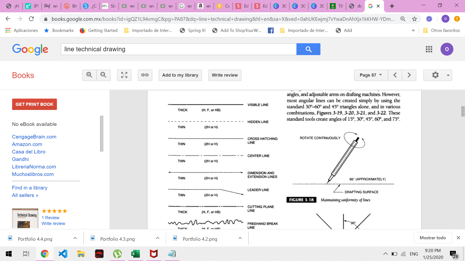
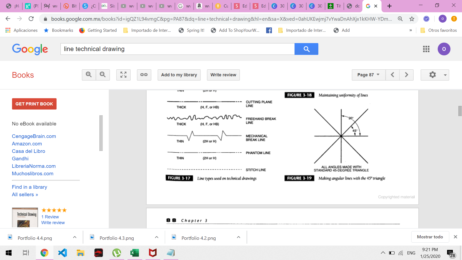
Drawing lines
Twelve basic types of lines are used in manual drafting, each has its own individual characteristics.
15º increments with triangles

Portfolio draft (3)
All of your activities need to be made on a letter size blank sheet of paper. For this excercises draw a frame of 1 cm from the border of the page.
Activity description:
- Draw a frame of 1 cm
-
Draw a title block and fill the corresponding sections with relevant information (180x 27 mm)
- Title: Third draft, Created by: your name, Approved by: professor name, Date of issue: Today, Document type: Draft, Legal Owner: CETYS
- Draw a central axis of 18 cm
- Draw angled lines every 15 degrees .
Portfolio draft (4)

Laboratory sessions
CAT´S LAB A
Equal divisions in a box
Drawing
Bisector line
Technical Drawing W2-3
By oscaralonso11


