Watching Superconducting Qubits with Microwaves


Justin Dressel
Institute for Quantum Studies, Chapman University
Keio University, July 17 2018



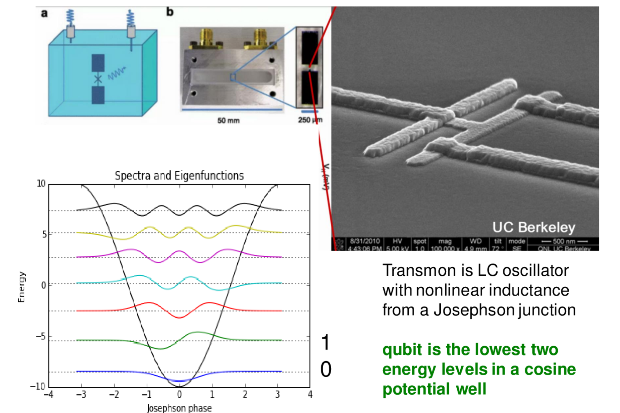
Superconducting Qubits
Mesoscopic quantum coherence of collective charge motion at \(\mu\)m scale
EM Fields produced by charge motion described by Circuit QED
Lowest levels of anharmonic oscillator potentials treated as artificial atoms

Typical Transmon Parameters
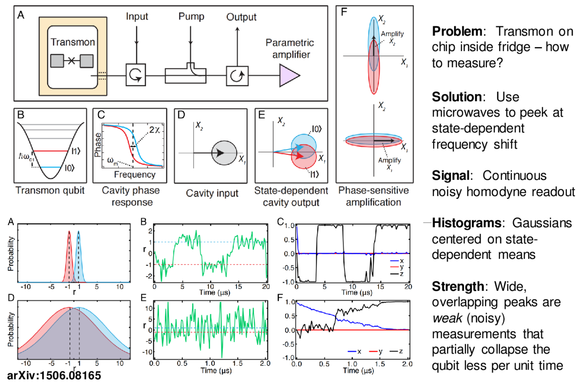
Microwave Measurement
Note : Without a quantum-limited amplifier, this doesn't work!
The Josephson Parametric Amplifier (JPA) and Traveling Wave Parametric Amplifier (TWPA) boost signal enough for later HEMTs in the readout chain to resolve the information.

"3D Transmon"
Cavity mode:
Detuned (dispersive) regime (RWA):
X-X Coupling:
Korotkov group, Phys. Rev. A 92, 012325 (2015)
Martinis group, Phys. Rev. Lett. 117, 190503 (2016)
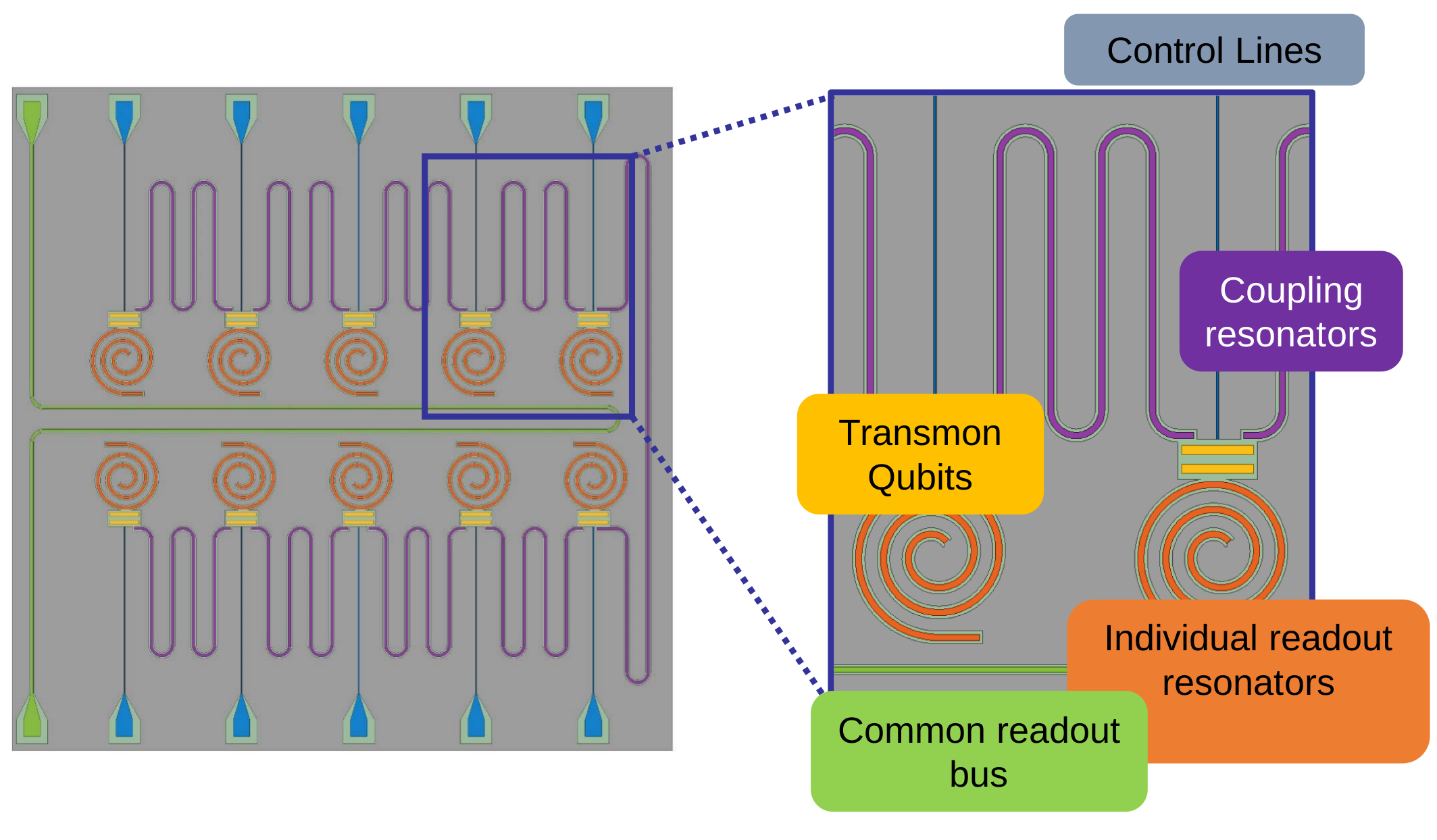
2D planar chip schematic

Bus acts as Purcell filter, coupled to traveling wave parametric amplifier (TWPA)
Similar parameters:
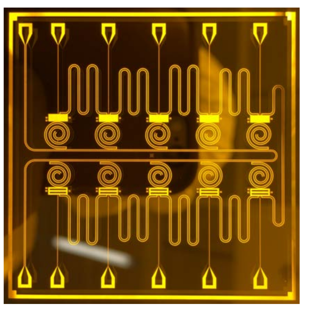
v1
v3
Coming soon: two-layer design of 20+ qubits
separated from control circuitry
(similar to Google Bristlecone + IBM Q)
Now on v8+
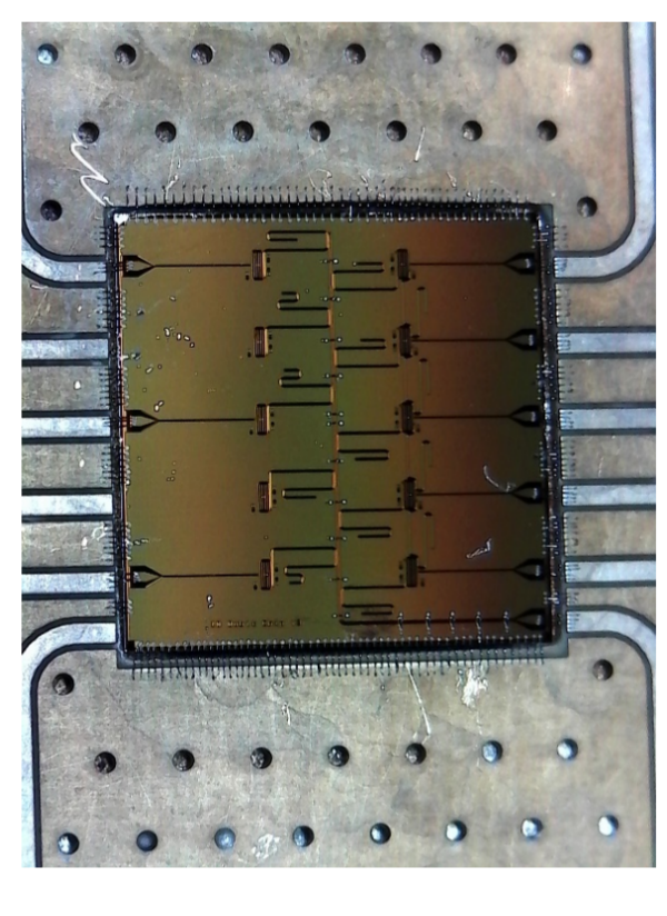
UCB 2D planar chip
Multiplexed 10 qubit control and readout

Single shot "projective" readout :
typical quantum computing goal
Microwave Measurement

"Continuous" weak measurements :
more gentle monitoring
Microwave Measurement
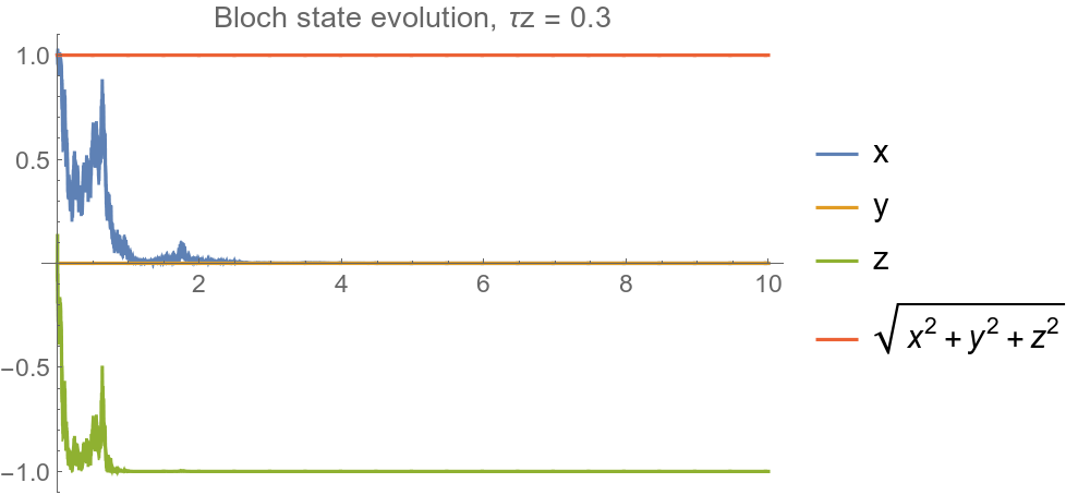
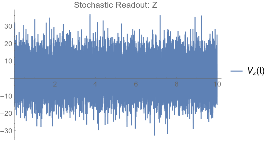
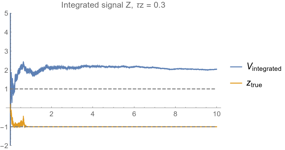
Voltage value identified with Z=-1
Example: QND projective collapse to Z = -1
Location of qubit eigenvalues on the voltage axis are determined by the steady-state averaged voltages observed in the projective readout
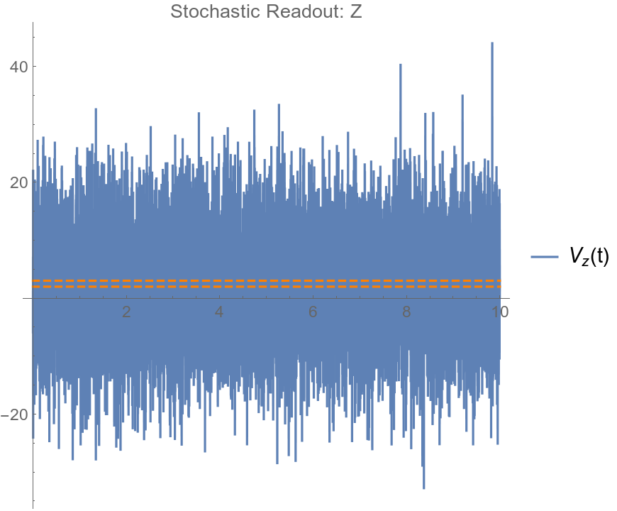
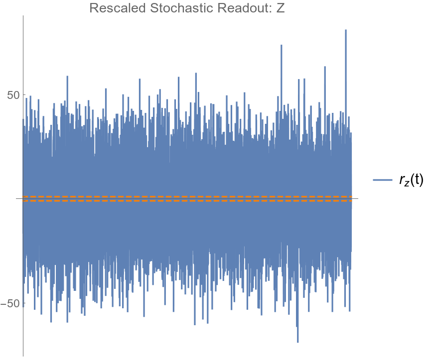
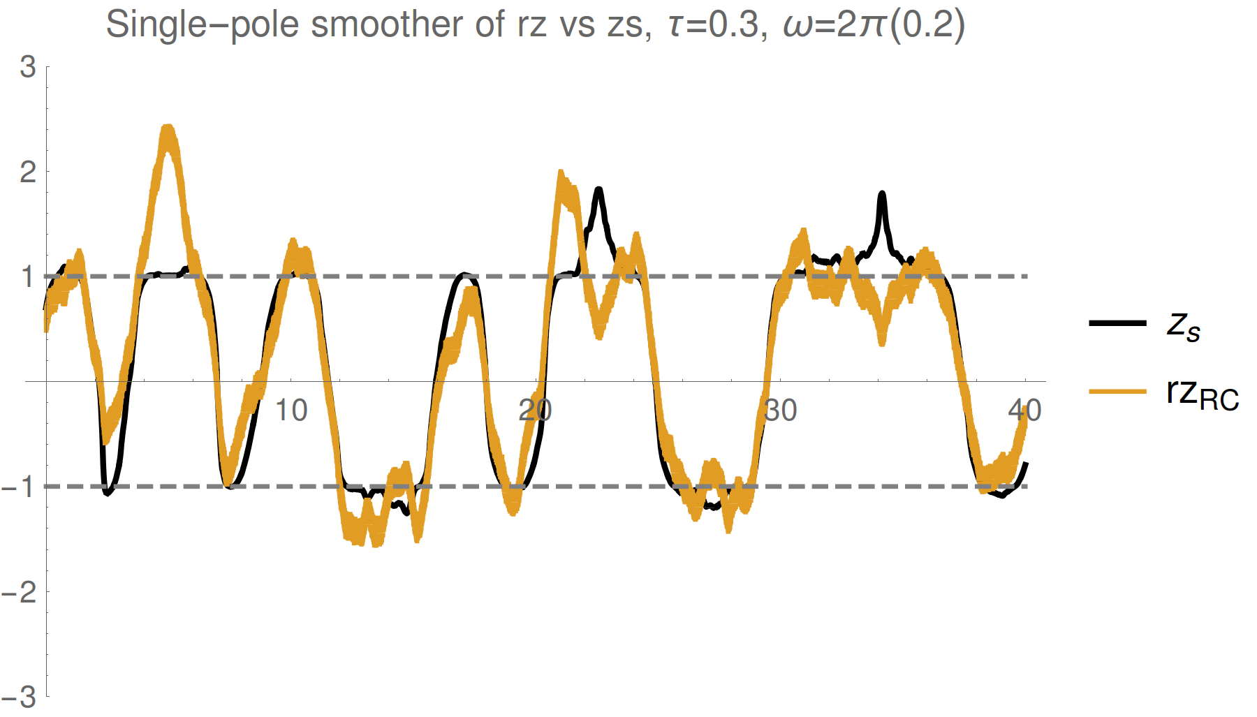
Observed average voltages from separate projective measurement calibration experiments
Rescaling to match Z
Markovian Qubit Filtering
Discrete Update Model:
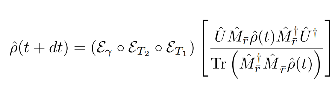
(Approximately Gaussian readout with phase-backaction, depends on quadrature phase of amplifier)
Koroktov, Phys. Rev. A 94, 042326 (2016)
JD group, Phys. Rev. A 96, 022311 (2017)
Assumptions:
- Finite detector bandwidth \(\Rightarrow\) discrete voltages \(V_k\) averaged over time bins of length dt
- Resonator in steady state
- The qubit dynamics slow compared to relaxation to resonator steady state
- The timescale for achieving unit signal-to-noise when integrating the normalized signal remains constant
Phenomenological nonidealities:
Stochastic master equation model:
Alternative View: Continuous Limit
Effective stochastic readout:
JD group, Phys. Rev. A 94, 062119 (2016)
JD group, Phys. Rev. A 96, 022311 (2017)

Calibration parameters required:
Common approach in literature, but less useful for data processing
A Brief Tour of Recent Results
Individual quantum state trajectories filtered from the readout are verified via spot checking predicted subensembles with tomography
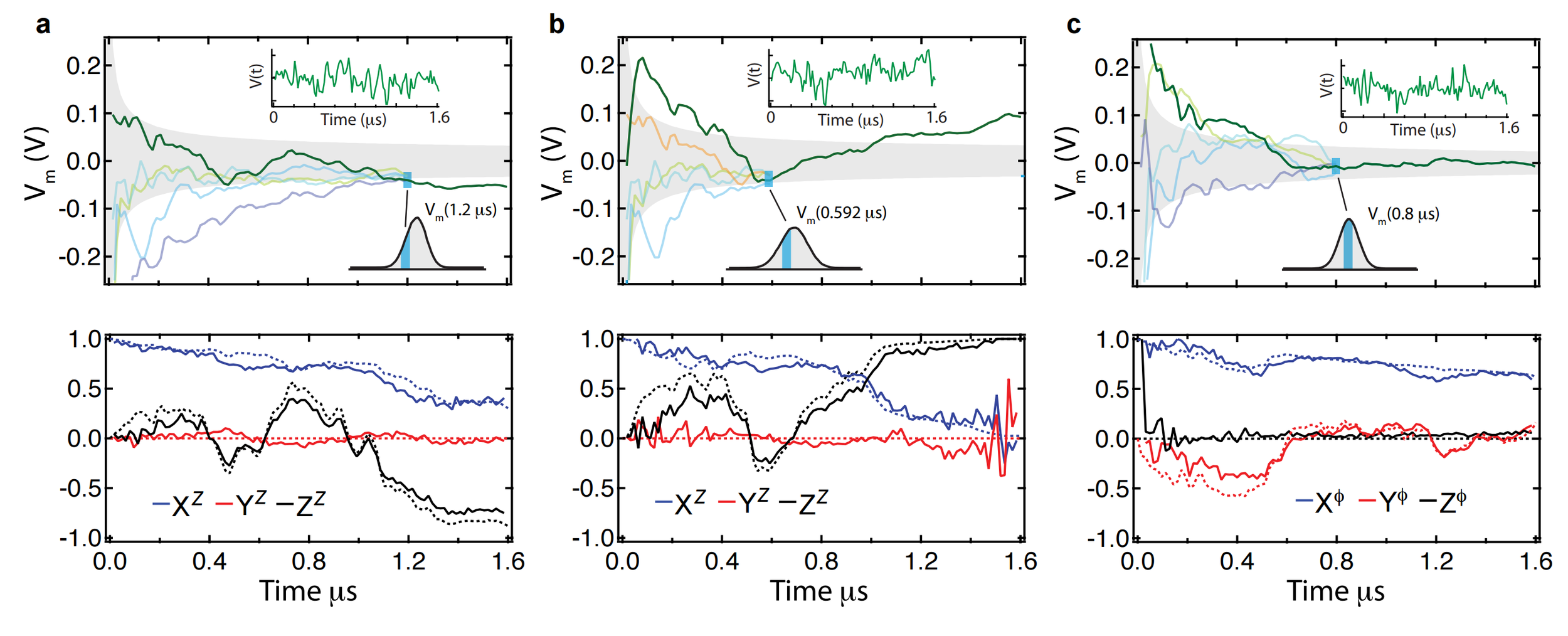
Approach:
- Perform a random tomographic pulse at the end of each data run
- Spot check subensembles of data to verify tomography of final state
Quantum Trajectories
Murch et al., Nature 502, 211 (2013)
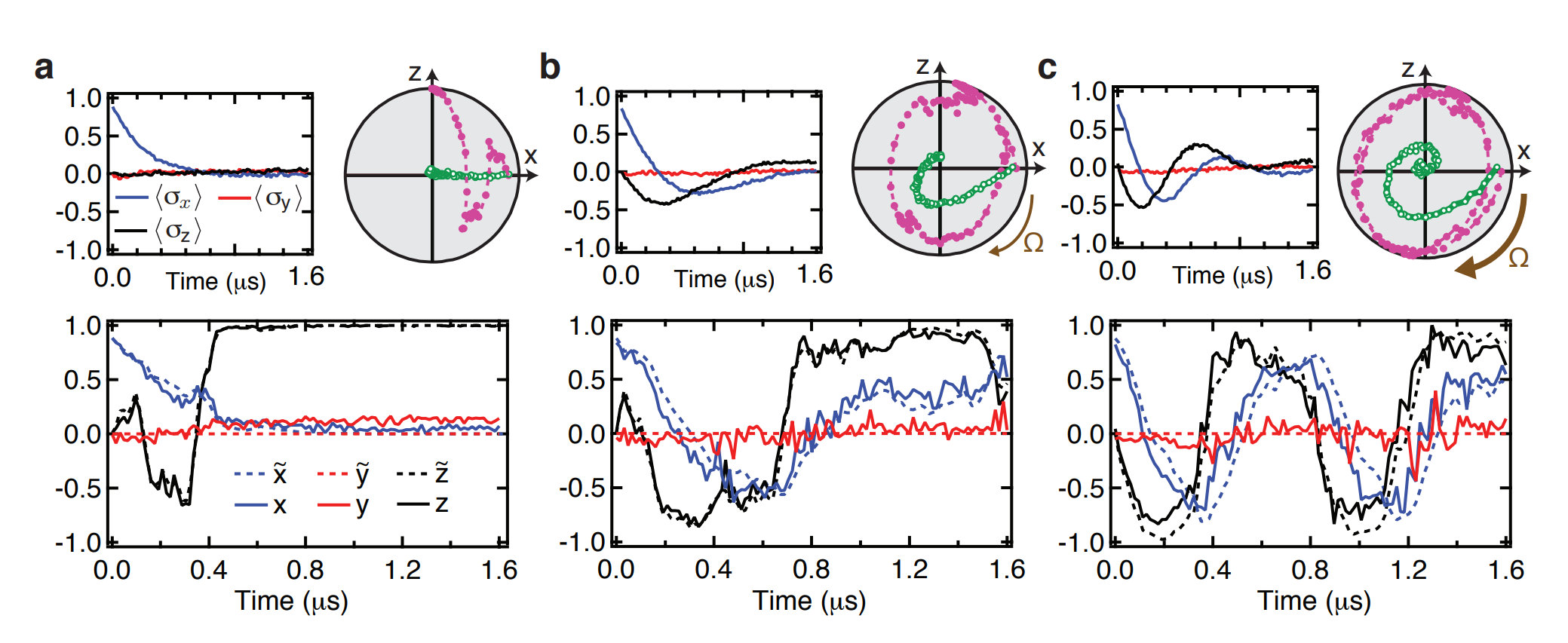
Monitored Rabi Drive
JD and Siddiqi Group, Nature 511, 570 (2014)
Partial collapses compete with unitary dynamics
Ensemble-averaging the stochastic evolution recovers the usual Lindblad dynamics
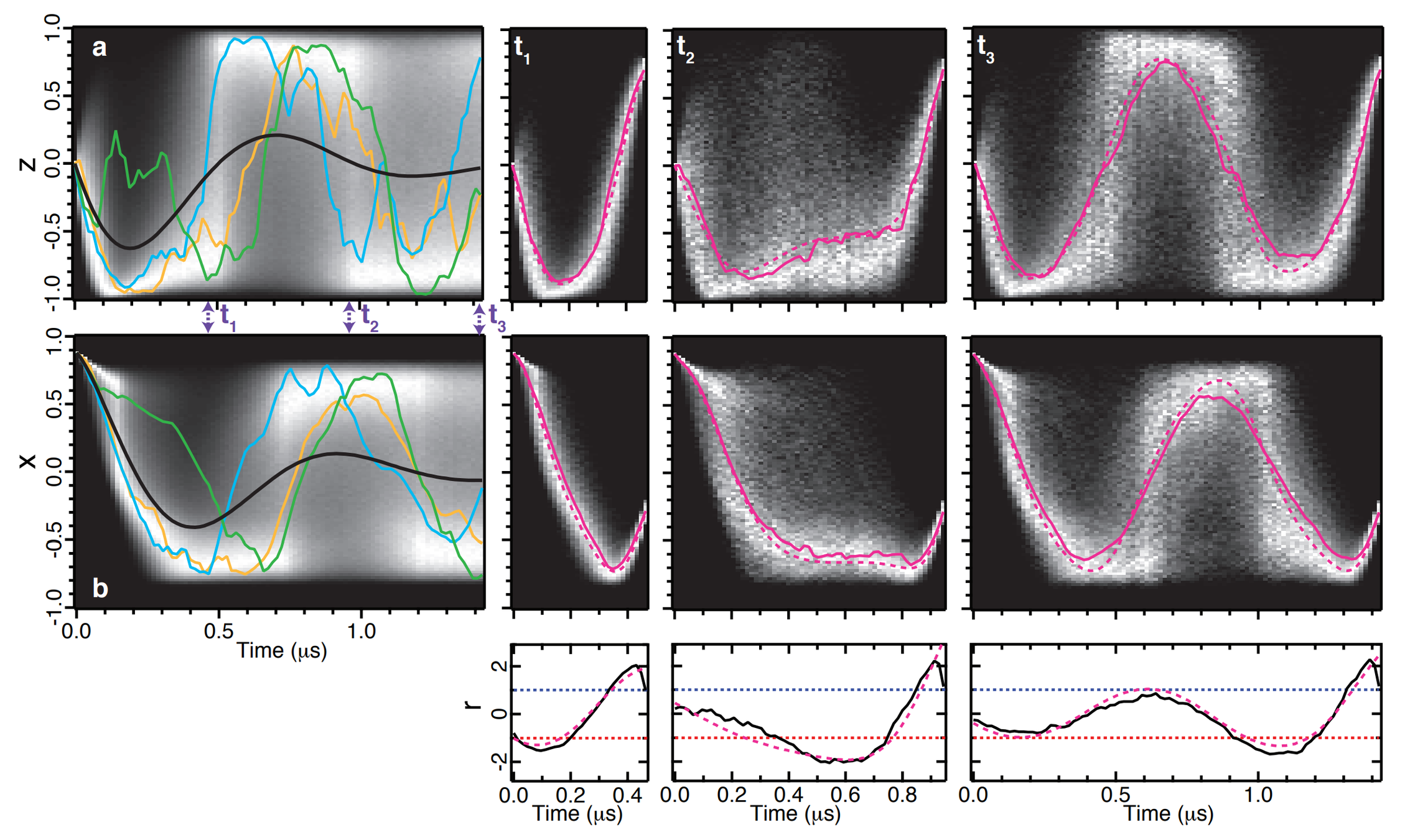
Conditioned State Dynamics
JD and Siddiqi Group, Nature 511, 570 (2014)
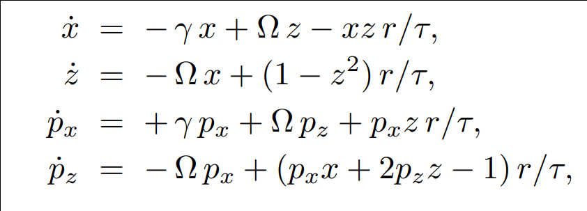
Experimental most probable path matches ODE solution derived from stochastic path integral
JD and Jordan Group, PRA 88, 042110 (2013)

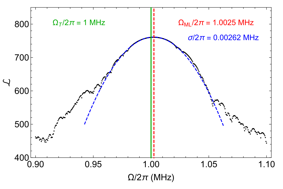
Tracking Drifting Parameters
Maximum likelihood techniques allow extraction of parameters drifts from stochastic records with reasonable precision
JD and Jordan Group, PRA 95, 012314 (2017)
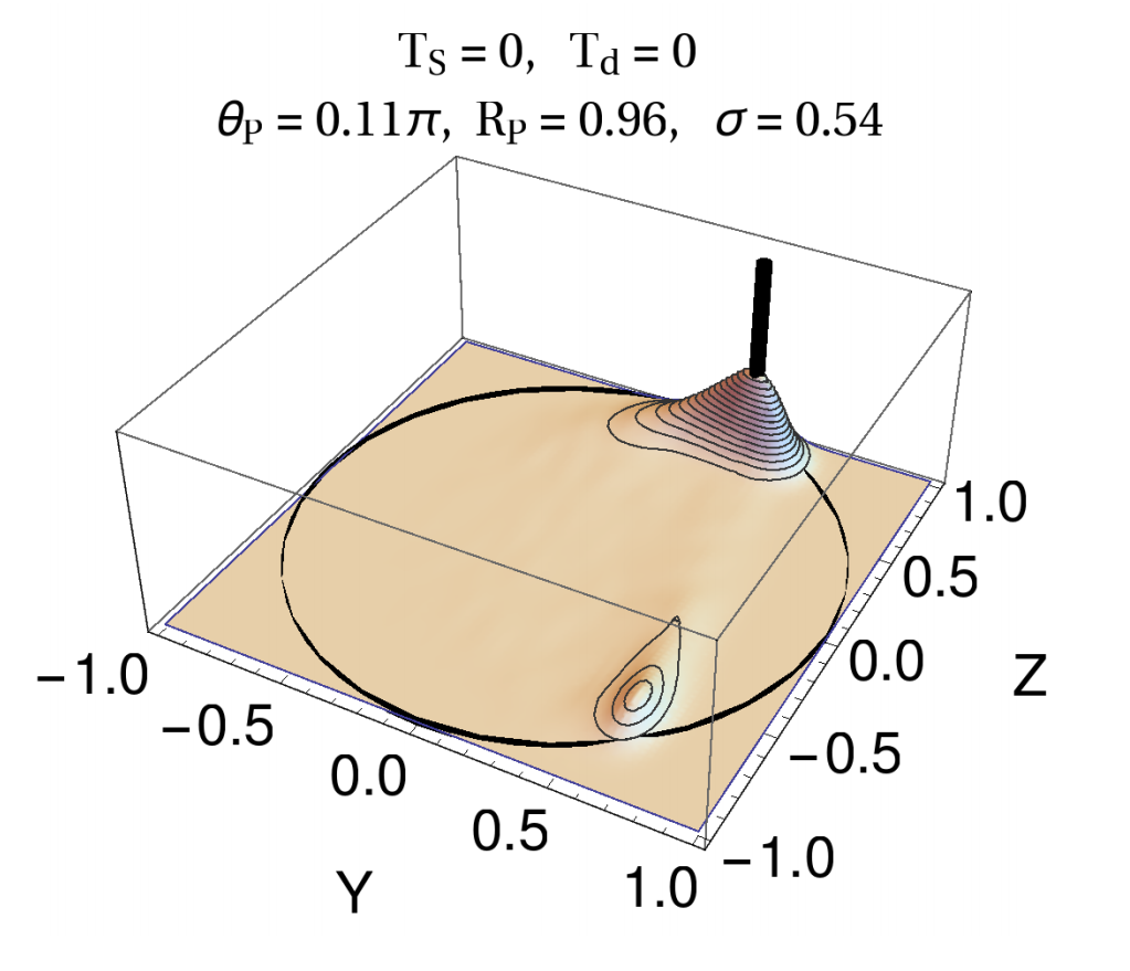
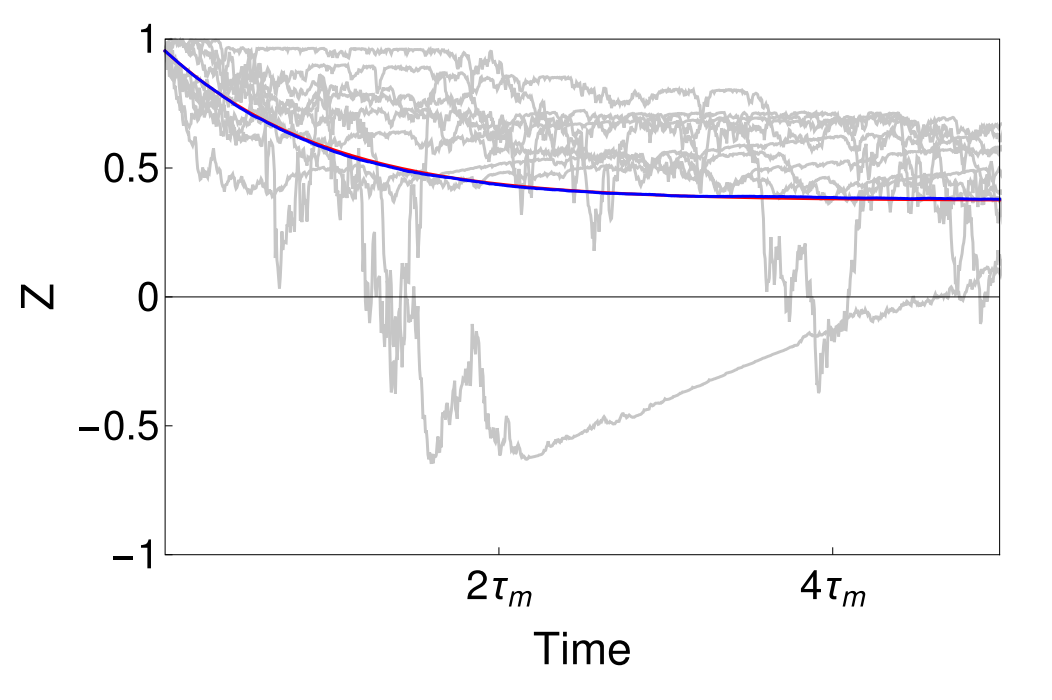
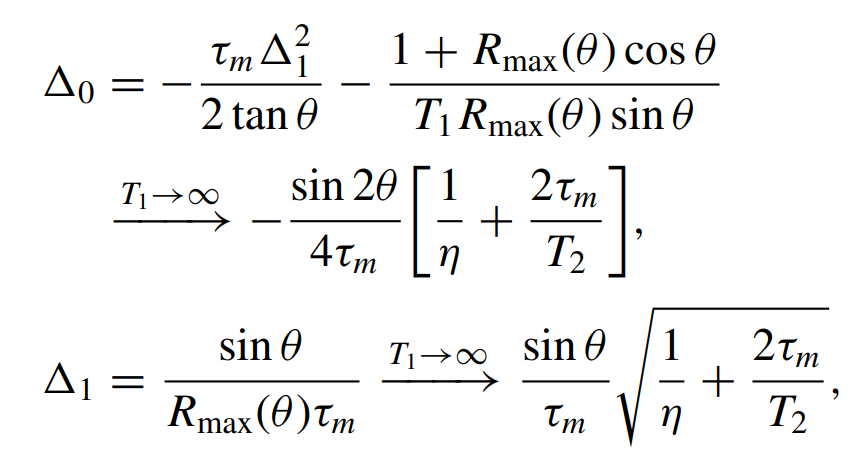
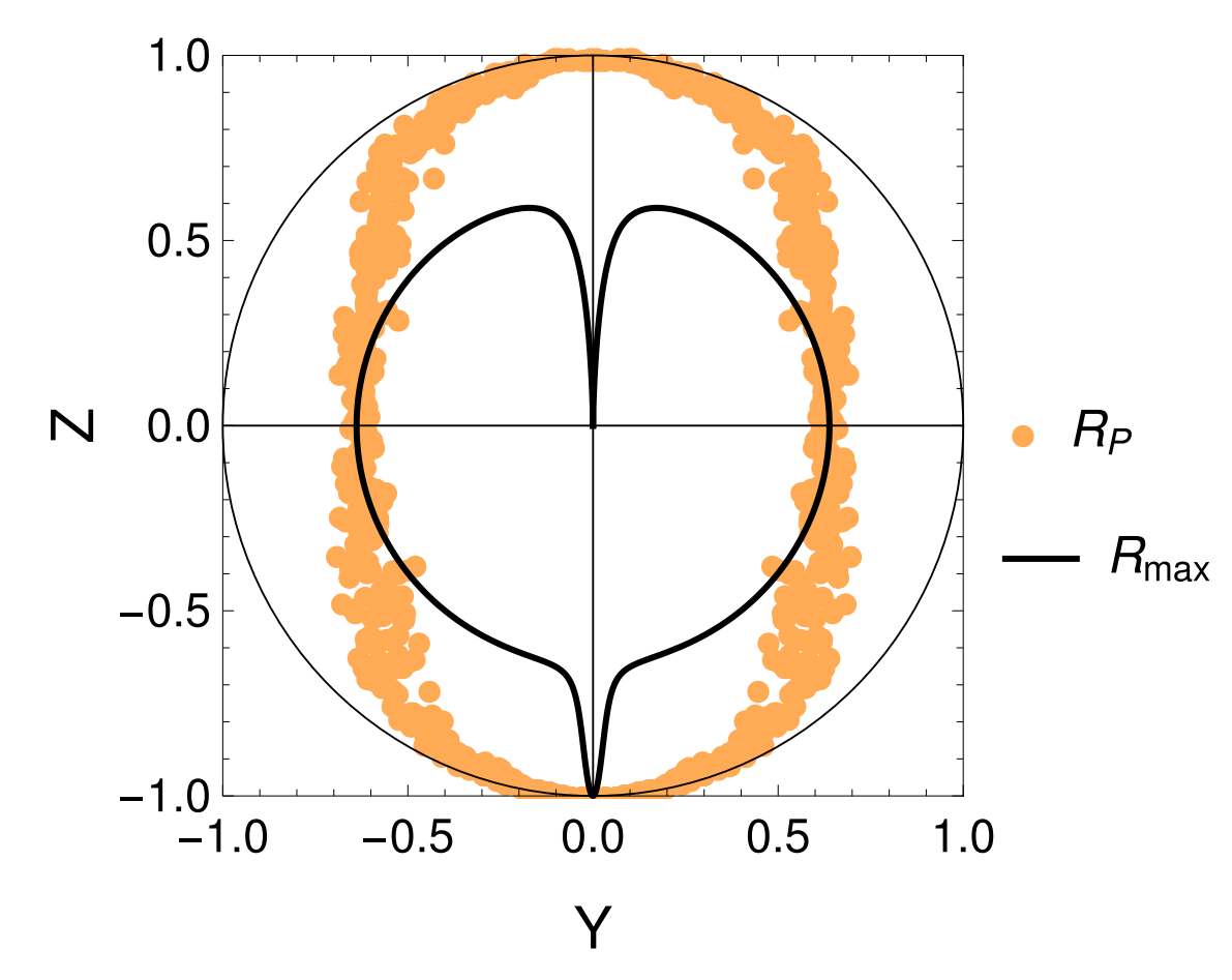
Feedback State Stabilization
Linear feedback (with very small temporal delays) can stabilize the qubit state to targeted regions of the Bloch sphere.
JD and Jordan Group, PRA 96, 022311 (2017)

- Symmetrically detuned pumps
- Beats stroboscopically measure rotating qubit
- Yields displacement coupling
- Allows tunable measurement axis
- Multiple cavity modes = multiple observables
Displacement coupling:
Siddiqi group, Nature 538, 491 (2016)
Stroboscopic Displacement Coupling
Rotating frame:
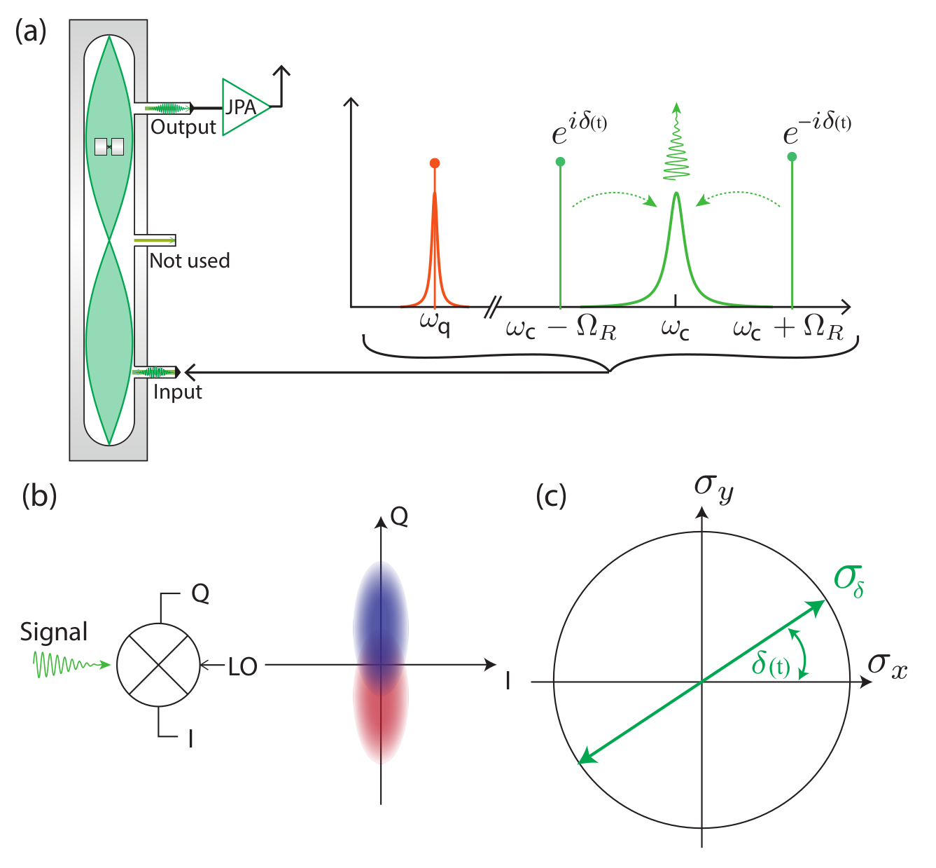
Incoherent Zeno-Dragging Qubit Gate
Idea : use time-varying measurement axes to drag the quantum state around the Bloch sphere using the quantum Zeno effect
The record tracks the state well in this regime, so can be used as a herald for high-fidelity gates
Non-unitary gate
(measurement-based)

Stroboscopic displacement coupling can be time-varying
JD, Siddiqi group, PRL 120, 020505 (2018)
Jumps : Faster drag speeds allow trajectories to jump to the opposite pole, decreasing ensemble-averaged dragging fidelity
Jump-axis : Dragging dynamics causes lag of actual Zeno-pinned behind the measurement axis by a fixed angle
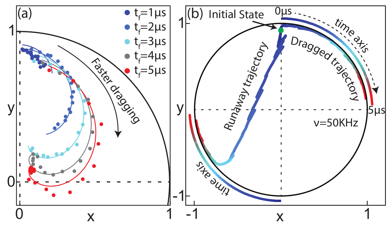

JD, Siddiqi group, PRL 120, 020505 (2018)
Pinned to poles : Other than the jumps, state remain pinned to lagged measurement poles
Incoherent Zeno-Dragging Qubit Gate
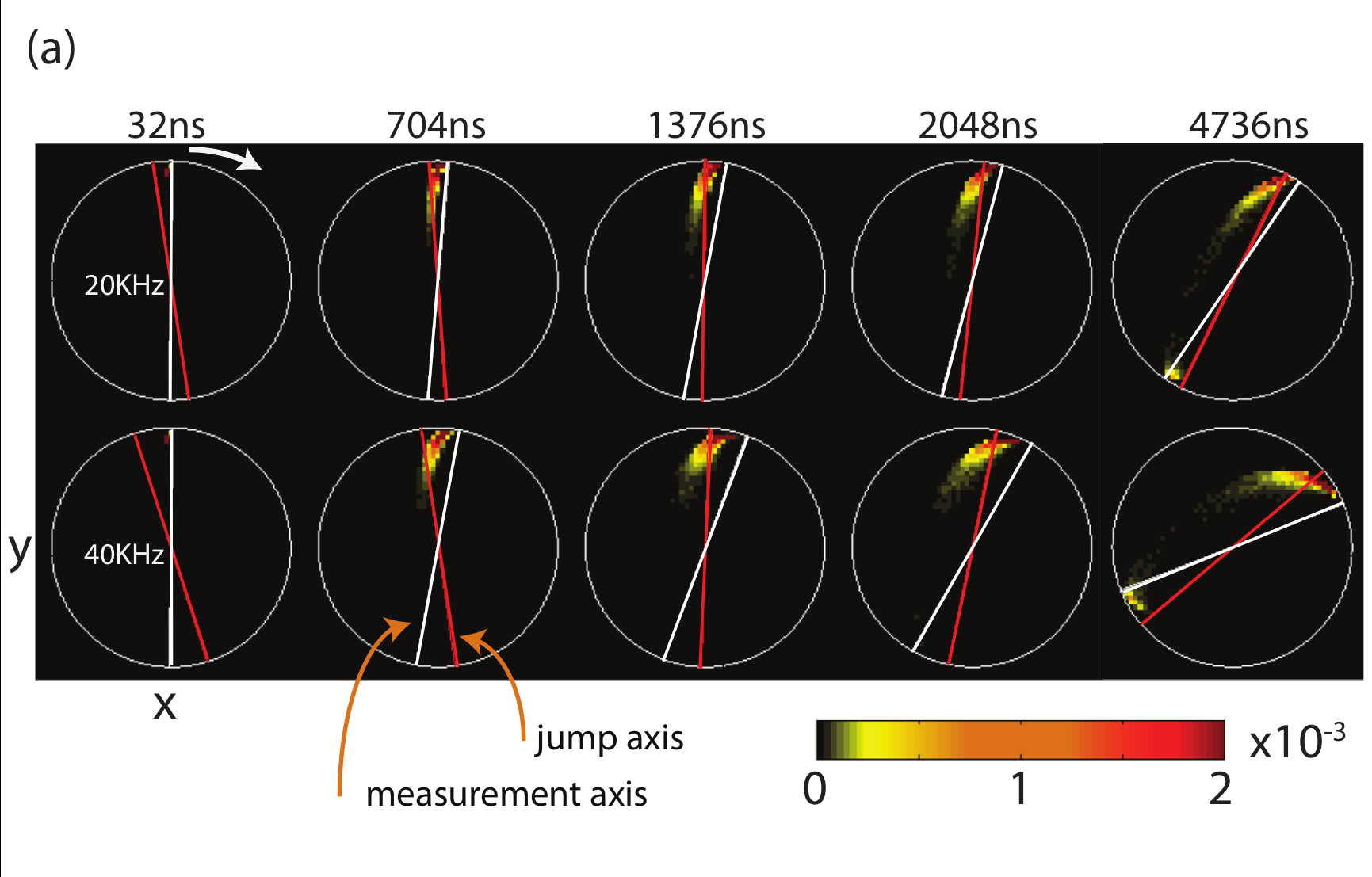

State collapses to jump-axis
JD, Siddiqi group, PRL 120, 020505 (2018)
Incoherent Zeno-Dragging Qubit Gate
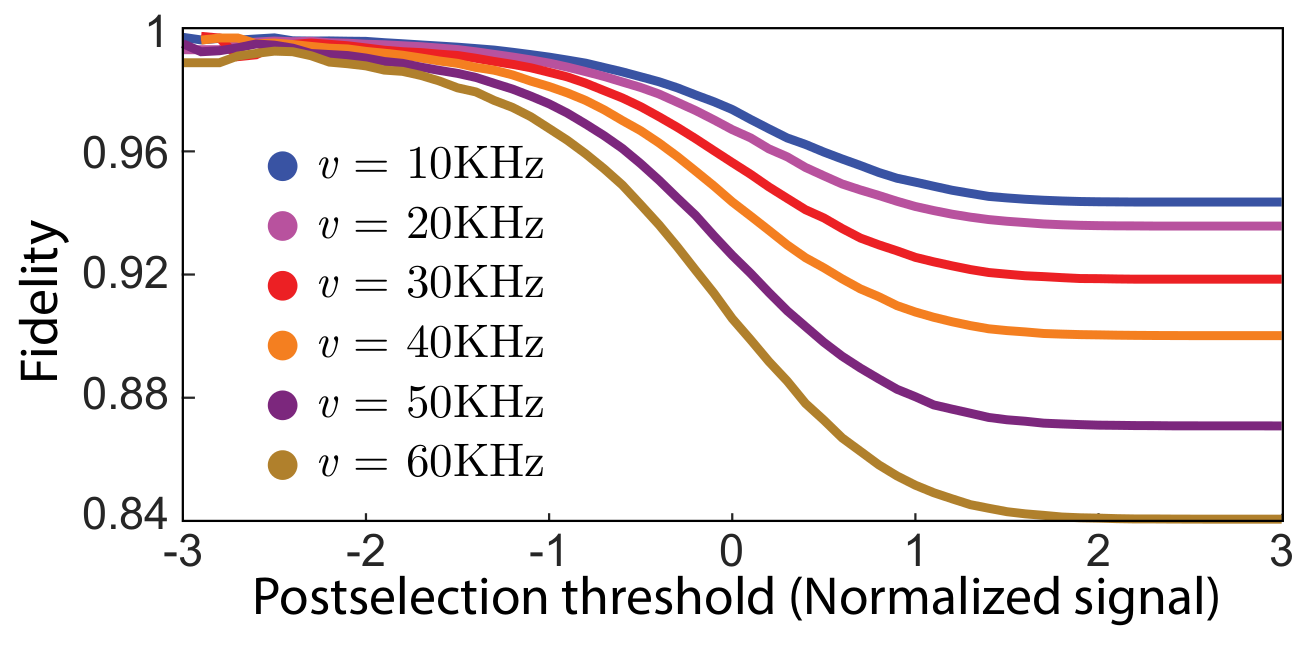
Post-selecting on trajectories with an average readout with a value >1 keeps only trajectories that did not jump, heralding a reasonably high-fidelity dragging gate for that subset
Alternatively, the jump may be observed, then corrected later
JD, Siddiqi group, PRL 120, 020505 (2018)
Incoherent Zeno-Dragging Qubit Gate
Siddiqi group, Nature 538, 491 (2016)
4 pumps, symmetrically detuned from 2 resonator modes
2 simultaneous noncommuting observables
Partial collapses compete with each other, preventing full collapse to a stationary state
If observables are maximally non-commuting, creates persistent phase-diffusion in Bloch sphere
Noncommuting Observable Measurement
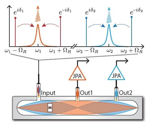
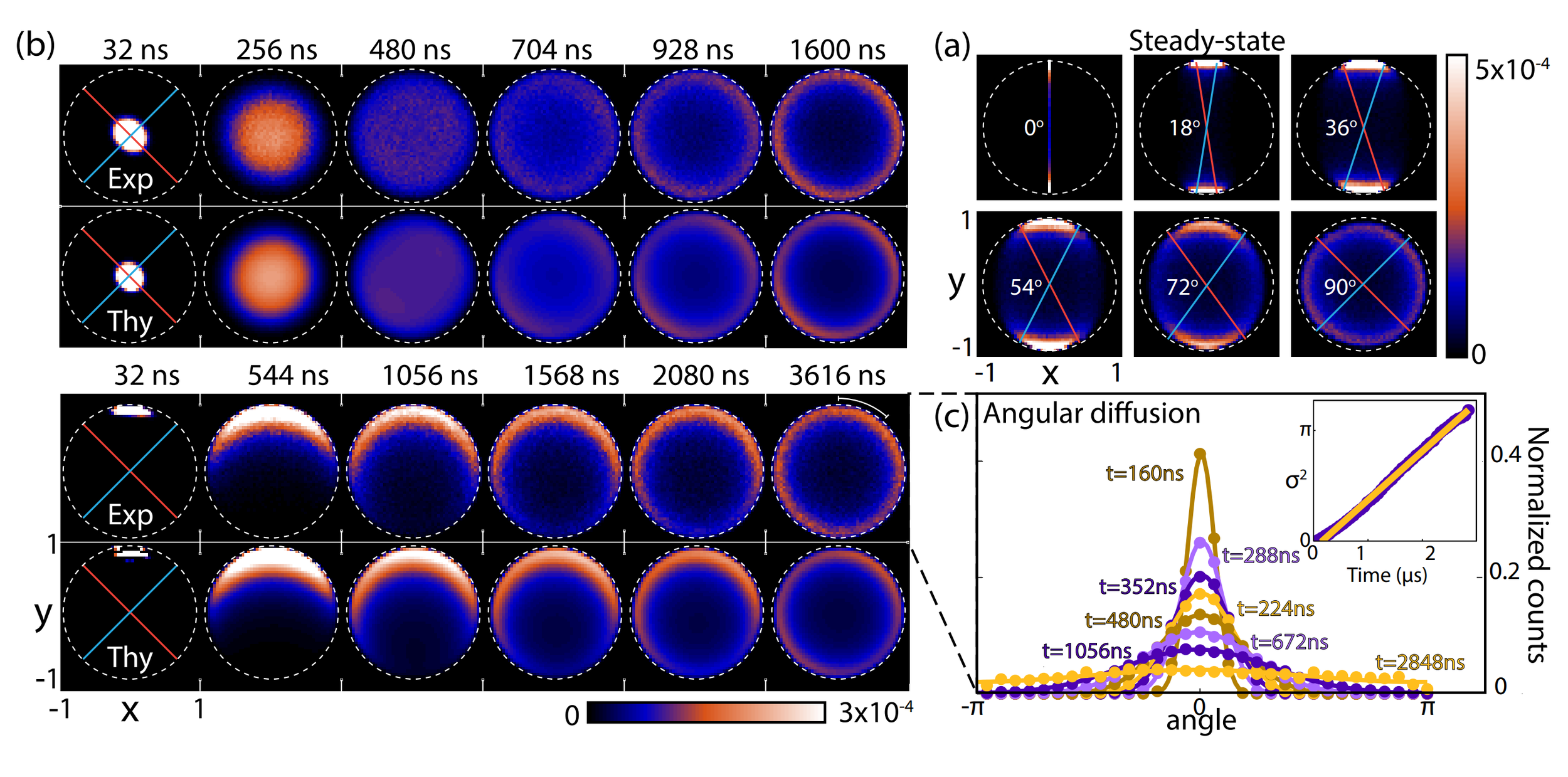
Siddiqi group, Nature 538, 491 (2016)
State purifies, but diffuses randomly
Basins of attraction if measurement axes are nearly aligned
Noncommuting Observable Measurement
Siddiqi group, Nature 538, 491 (2016)
State disturbance can be measured
Result agrees with the lower bound set by the Maccone-Pati relation involving the sum of variances:
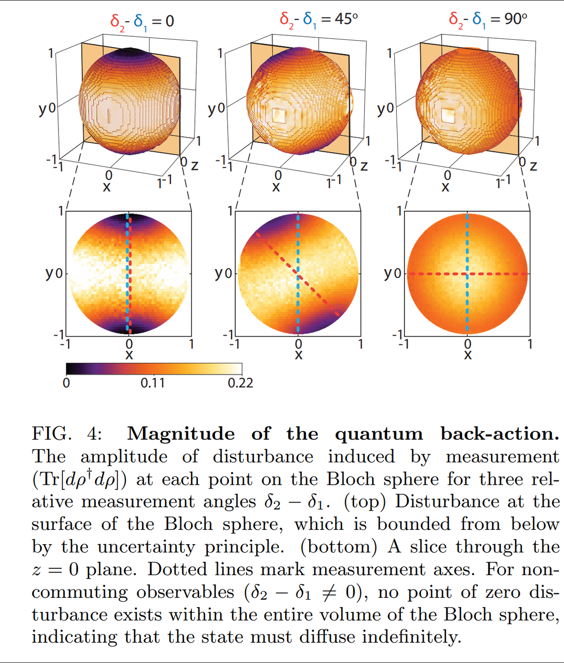

Uncertainty relation forces the random state diffusion when measuring incompatible axes
Noncommuting Observable Measurement
- Allows squeezed pump field
Siddiqi group, Phys. Rev. X 6, 031004 (2016)
Squeezed Displacement Coupling

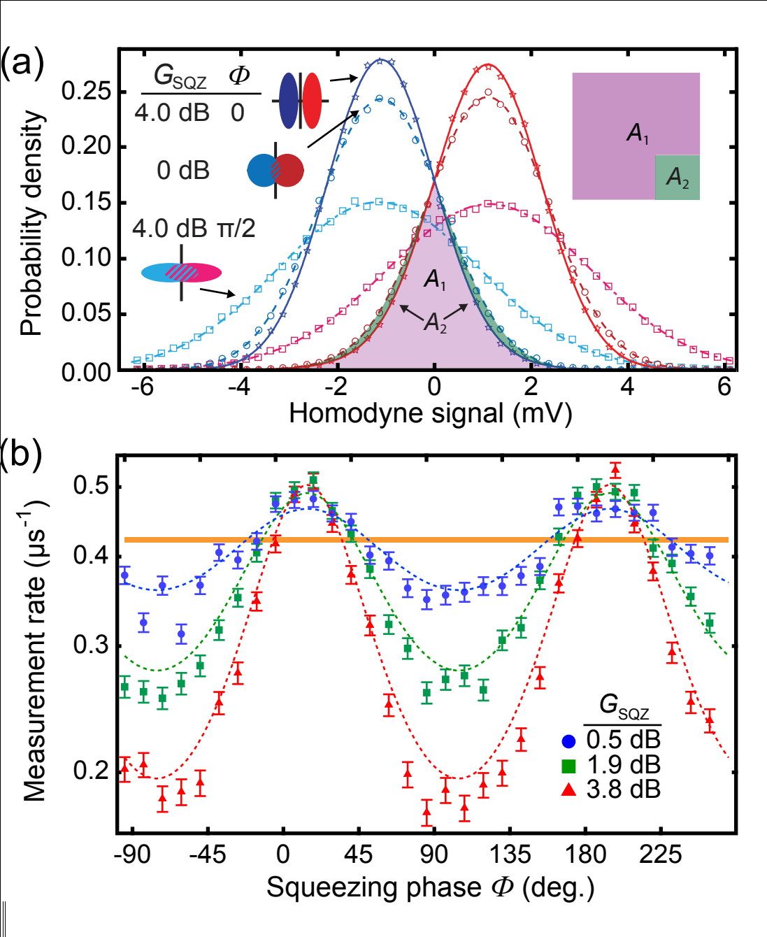
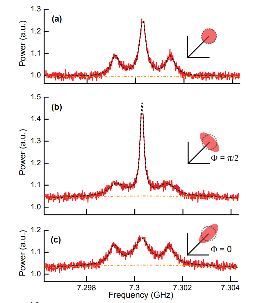
Siddiqi group, Phys. Rev. Lett. 120, 040505 (2018)
- Faster/slower measurement rates
- Squeezed Mollow triplets
Justin Dressel (PI)
José Raúl Gonzales Alonso (postdoc)
Razieh Mohseninia (postdoc)
Shiva Barzili (grad student)
Aaron Grisez (undergrad)
Michael Seaman (undergrad)
Amy Lam (undergrad)
William Parker (undergrad)
Luis Pedro García-Pintos (postdoc - now at UMB)
Taylor Lee Patti (undergrad - now at Harvard)

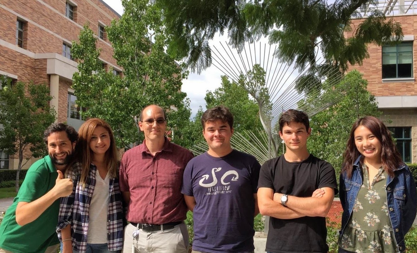
Chapman Crew
Conclusions

- Continuous measurements of quantum trajectories can now be realized in the laboratory with superconducting transmon circuits
- 10+ qubit planar 2D transmon designs in-hand at UCB
- Both dispersive and displacement measurements are possible
- Many interesting results so far, with more to come:
- Monitored Rabi drive and conditioned statistics
- Most probable path analyses
- Drifting parameter estimation
- State stabilization with feedback control
- Incoherent gates with Zeno-dragging
- Noncommuting observable measurement
- Squeezed state backaction
Thank you!
Circuit QED (Technical Details)
Definitions:
- Map hardware into a circuit of nodes
connected by branches (e.g., capacitor, inductor, etc.)
- Define voltage and current for each branch via EM fields,
as well as the flux and charge stored in each element:
- Define ground node and tree of active nodes connecting both capacitors and inductors - the fluxes to ground are the dynamical circuit variables
Vool, U., and Devoret, M. (2017) . doi: 10.1002/cta.2359.
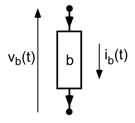
Branches \(b\in\mathcal{B}\) in path connecting node \(n\) to ground through capacitors
charge conjugate to node flux \(\phi_n\)
(\(+1\) capacitive, \(-1\) inductive)
- Primary circuit elements:
capacitor, inductor, and Josephson junction
Vool, U., and Devoret, M. (2017) . doi: 10.1002/cta.2359.
"Kinetic" energy:
"Potential" energy:
- Canonical quantization : (equivalent to quantizing \(\vec{E},\vec{B}\) )
Circuit QED (Technical Details)
(An)harmonic Oscillators
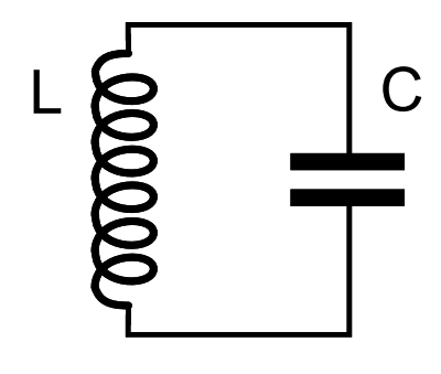
- Resonator:
Vool, U., and Devoret, M. (2017) . doi: 10.1002/cta.2359.
- Transmon:

Josephson junction shunted by large capacitance:
\(E_J/E_C \sim 100, \; E_J = \frac{(\hbar/2e)^2}{L_J}, \; E_C = \frac{e^2}{2C_J} \)
Qubit - Resonator Coupling
- Resonator + Transmon:
Vool, U., and Devoret, M. (2017) . doi: 10.1002/cta.2359.


Dispersive approximation, including rotating-wave approx (RWA):
Resonator frequency depends
on transmon energy levels
Watching Superconducting Qubits with Microwaves
By Justin Dressel
Watching Superconducting Qubits with Microwaves
QCMC2018, Baton Rouge LA, 3/13/2018 ; Keio University, 7/17/2018
- 2,706


