


Swapnil Kalhapure
Learner, researcher, hobby roboticist and backyard inventor.
Introductary session
23th August 2019
Swapnil Kalhapure
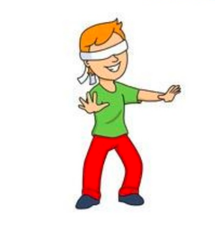
The ability to navigate in its environment, avoiding dangerous situations such as collisions and unsafe conditions (temperature, radiation, exposure to weather, etc.).
If the robot has a purpose that relates to specific places in the robot environment, it must find it.
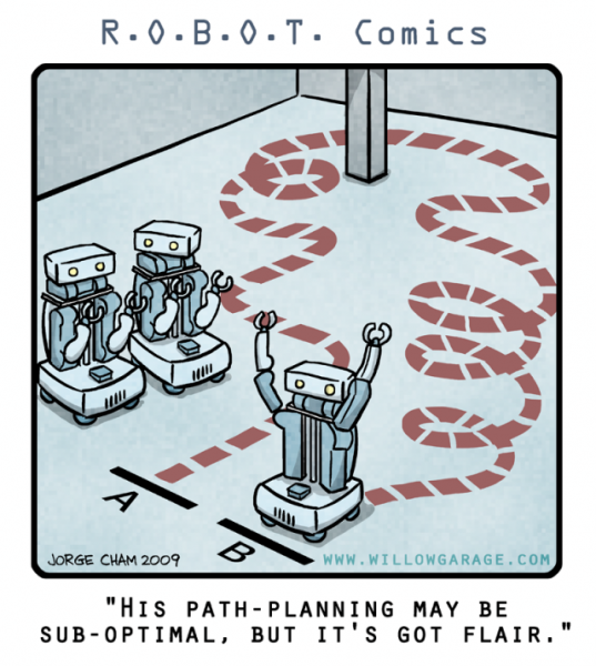
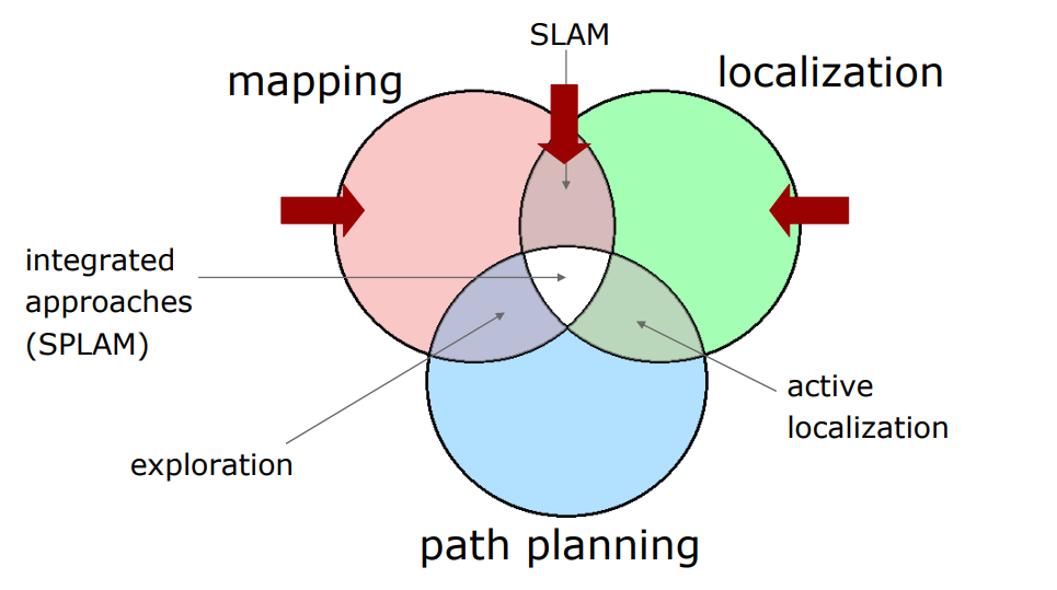
Robot navigation means the robot's ability to determine its own position in its frame of reference and then to plan a path towards some goal location.
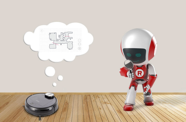
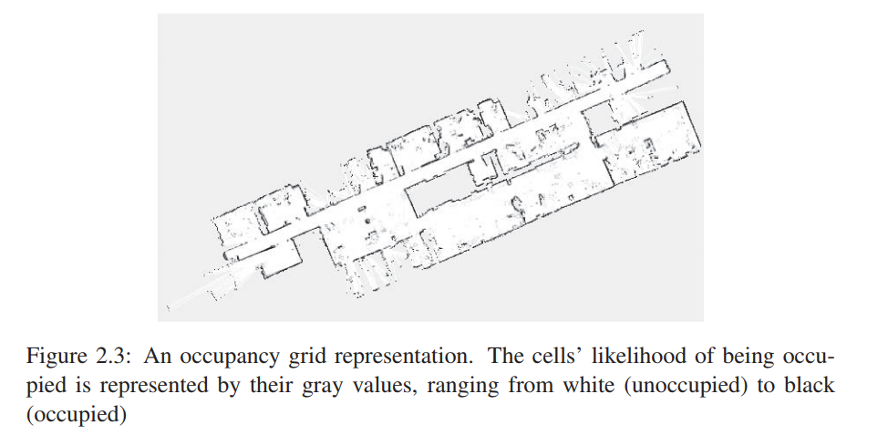
In order to navigate in its environment, the robot or any other mobility device requires representation, i.e. a map of the environment and the ability to interpret that representation.
Key Idea :
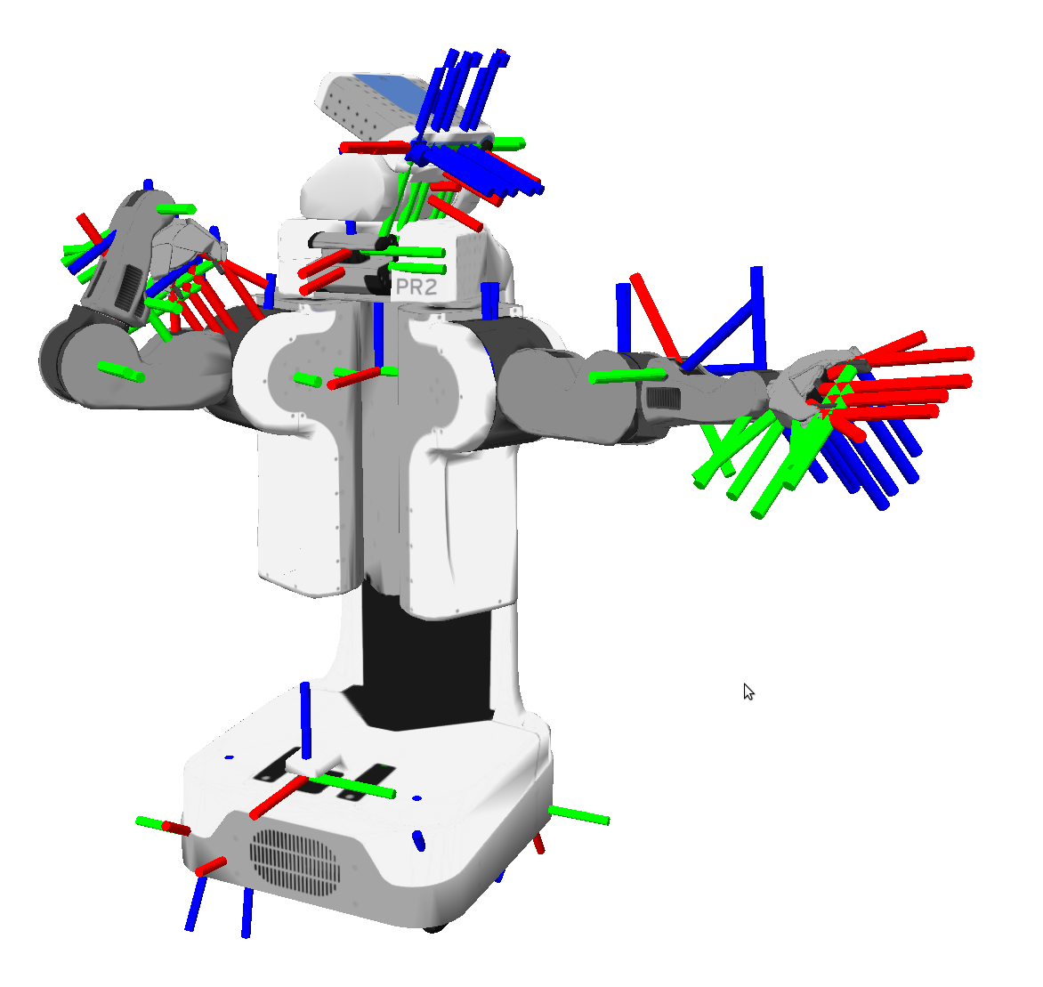
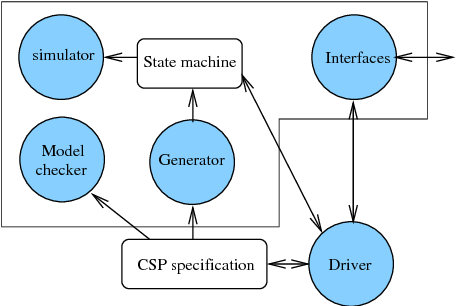
Robot's mechanical specifications
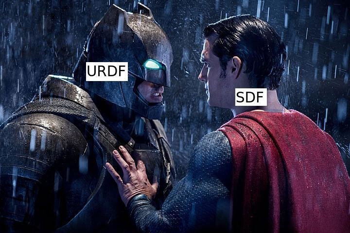
URDF: Unified Robot description format.
SRDF: Semantic robot description format.
kdl_parser: a kinematic and dynamic model from a urdf robot description.
convex_decomposition: A tool to auto-generate convex decomposed meshes for collision and visualization of robot links.
collada_urdf: A package to convert urdf files into collada files.
Source : http://wiki.ros.org/robot_model
URDF :
SRDF :
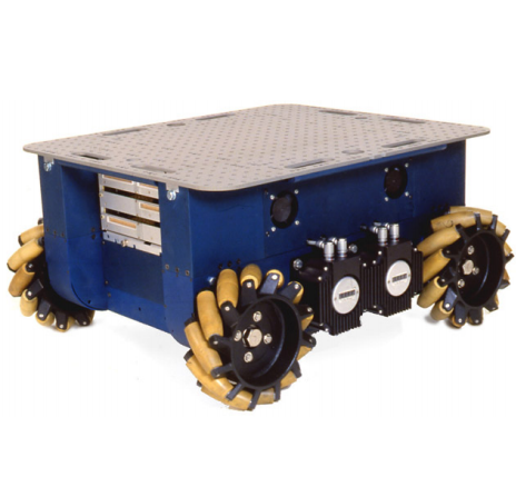
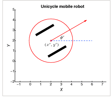
Robot's drive mechanism specifications :
Non-holonomic drive
Holonomic drive
Robot's motion specifications :
Robot motion is inherently uncertain! How can we model this uncertainty? a.k.a. probabilistic kinematics model.
Often finds two types of motion models:
Odometry-based.
Velocity-based.
Odometry-based models are used when systems are equipped with position feedback sensors.
Velocity-based models have to be applied to calculate the new pose based on the velocities and the time elapsed.
Odometry based motion model :
Velocity-based motion model :
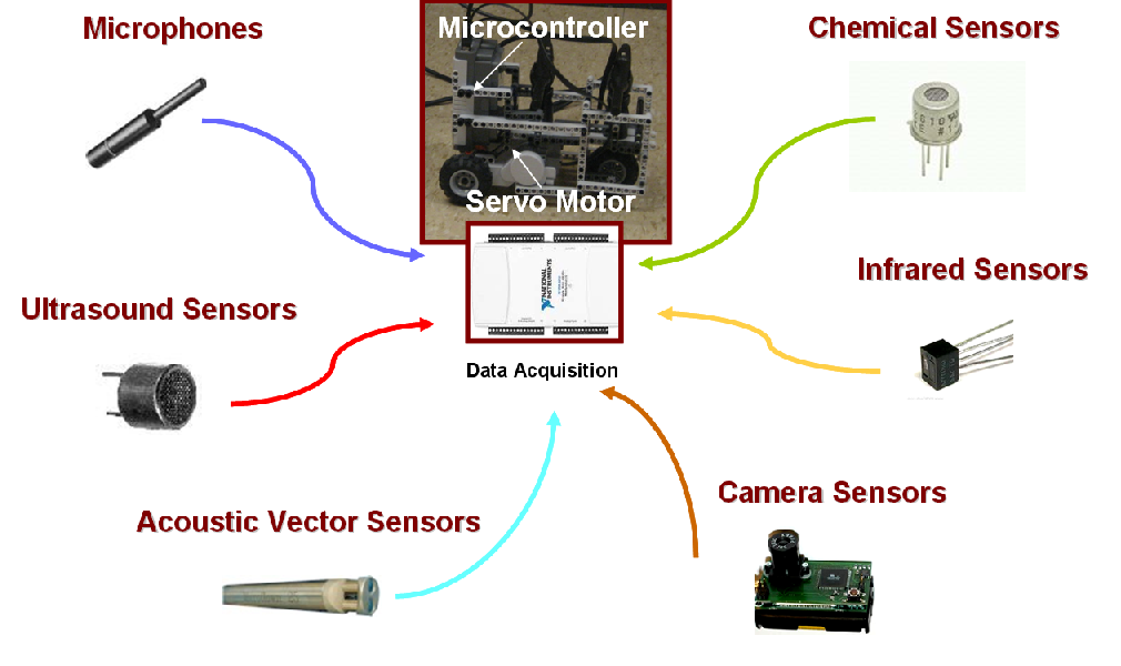
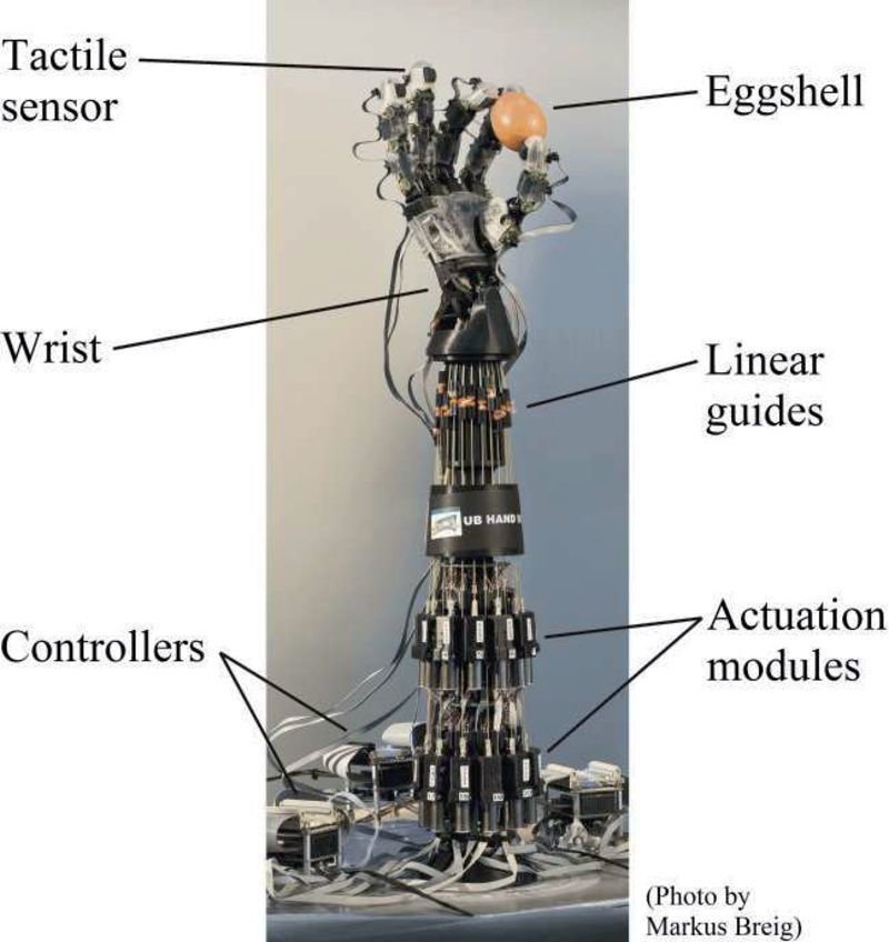
Robot's sensor devices specifications
Helps is discretizing real-world physical quantities.
Sensing is proximation only, will always be noisy.
Sensor data is usually subjected to post-processing, as in image processing, signal processing, etc.
3D vision, Lidar, Radars, Wheel encoders, IMU, monocular cameras, bump switch, etc.
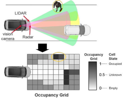
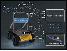
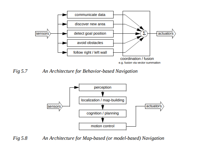
Robot's sensory data fusion
Combining of sensory data or data derived from disparate sources such that the resulting information has less uncertainty than would be possible when these sources were used individually.
Uncertainty reduction.
Direct fusion is the fusion of sensor data from a set of heterogeneous or homogeneous sensors, soft sensors.
Indirect fusion uses information sources like a priori knowledge about the environment and human input.
Sensor fusion is the art of combining multiple physical sensors to produce accurate "ground truth", even though each sensor might be unreliable on its own
Blind spots get smaller the more sensors you have
But the math gets harder in order to deal with the resulting fuzziness
Modern algorithms for doing sensor fusion are “Belief Propagation” systems—the Kalman filter being the classic example
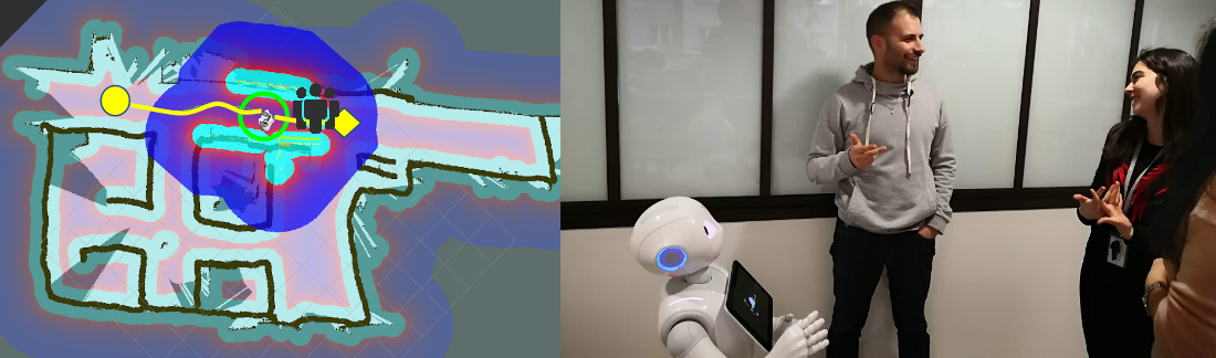
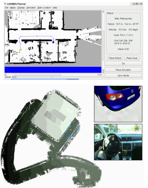
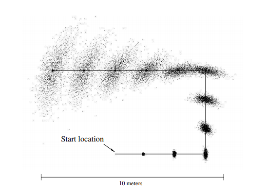
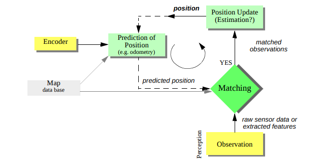
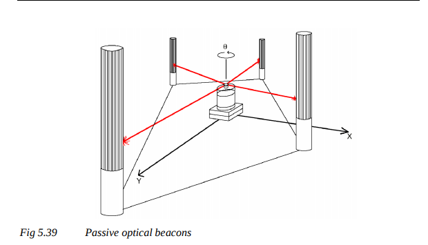
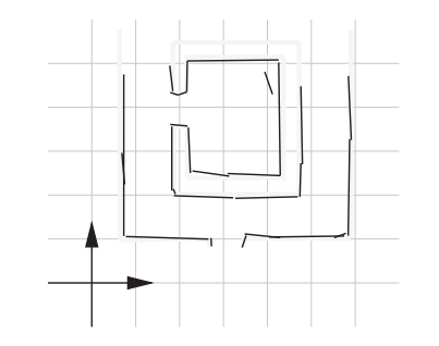
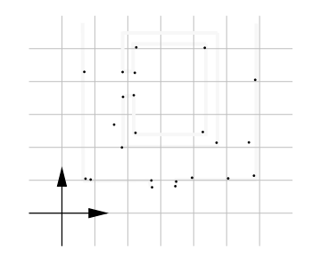
General schematic for mobile robot localization
Source : http://wiki.ros.org/amcl
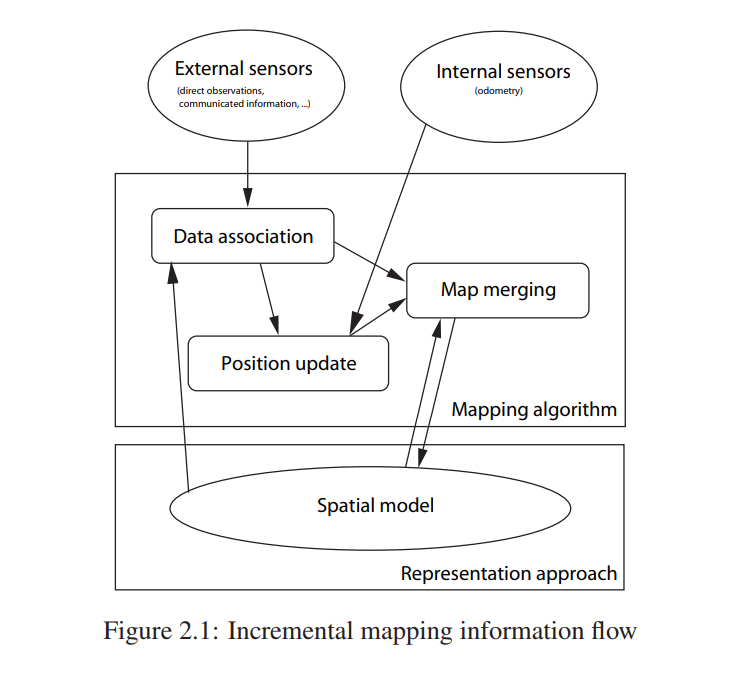
Most approaches to robot mapping are incremental, in the sense
Localization step -> data association step - > position update
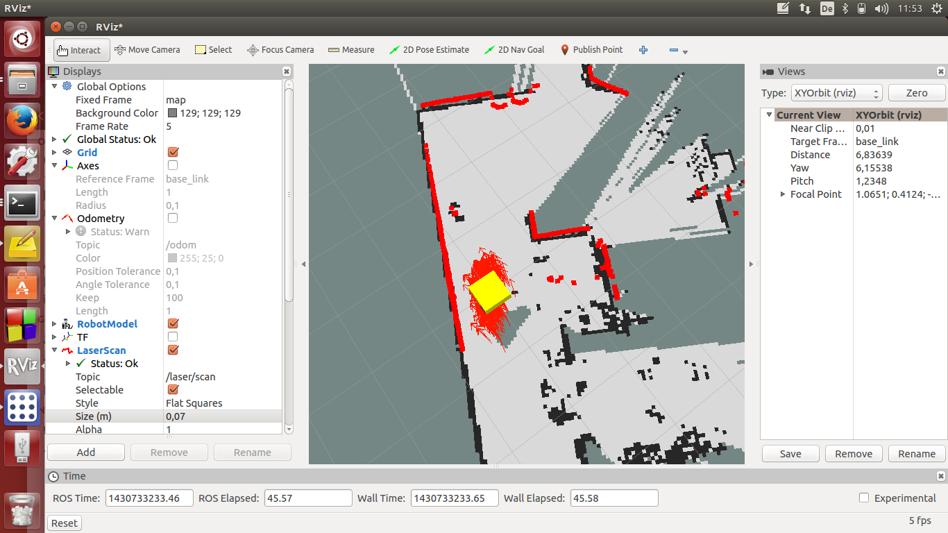
Gmapping :
Hector :
Cartographer :
Source : http://wiki.ros.org/map_server
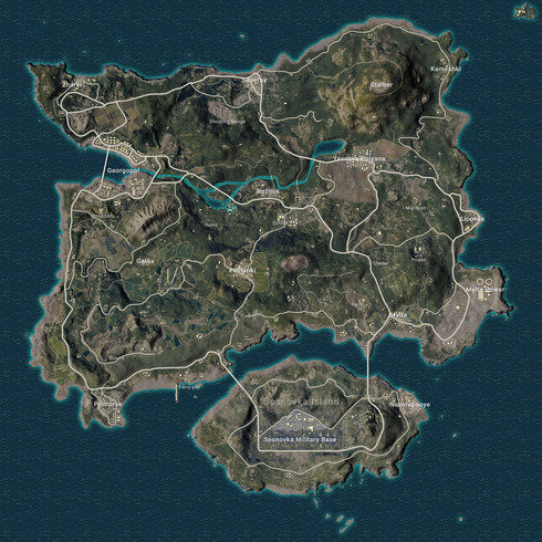
Source : https://pubgmap.io/
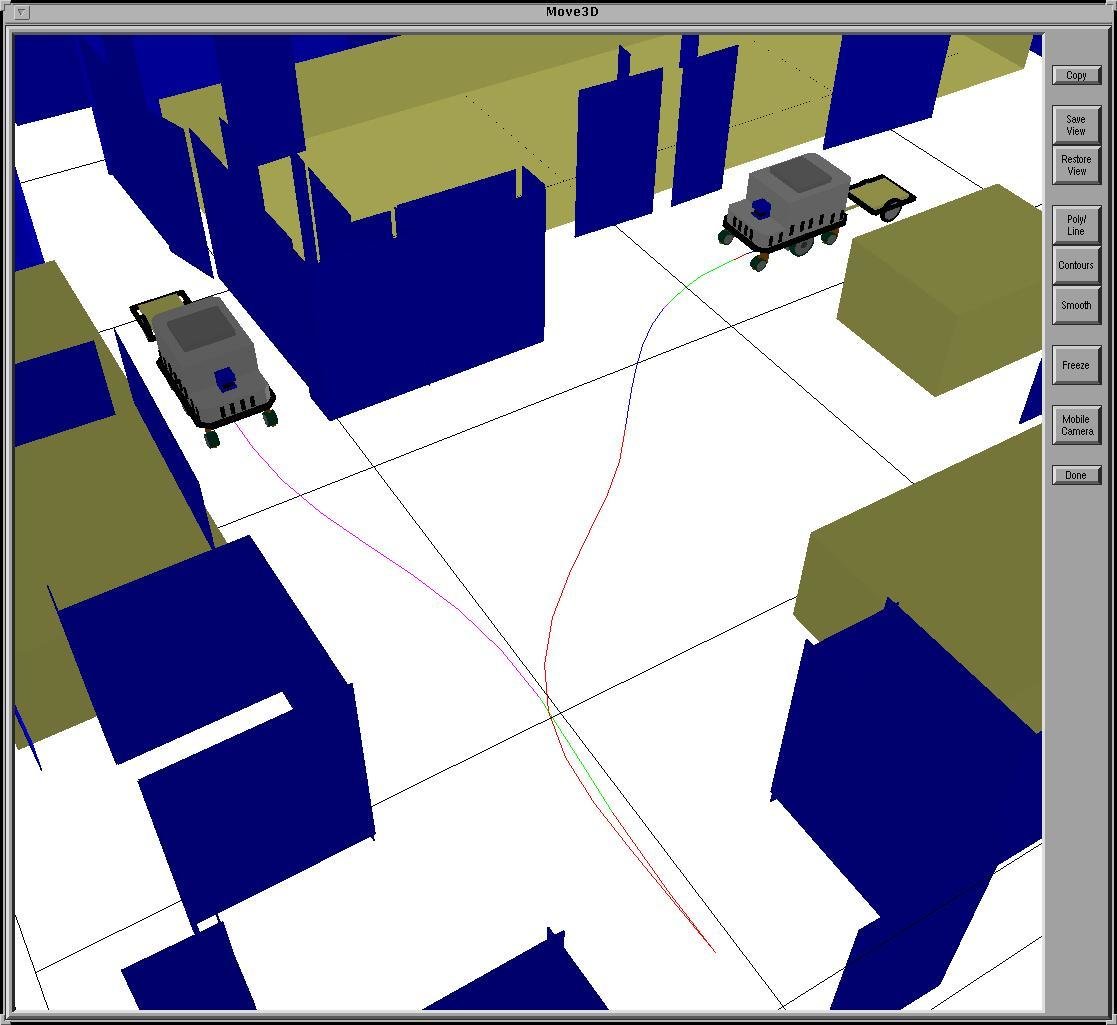
The problem of motion planning can be
stated as follows. Given:
Find a path that moves the robot
gradually from start to goal while
never touching any obstacle
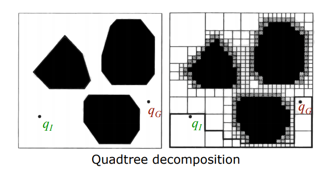
Combinatorial planning :
Sampling-based planning :
C- Planning :
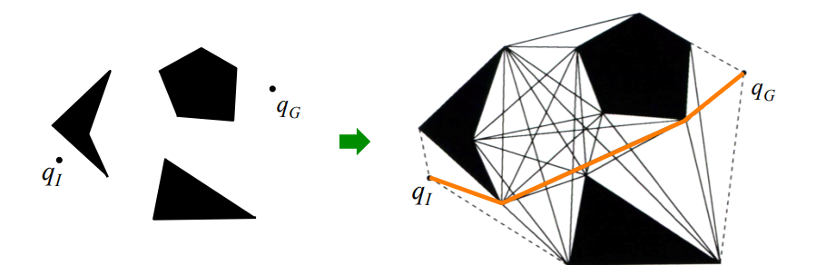
Visibility graph methods
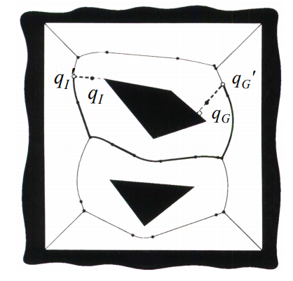
Voronoi Diagram methods
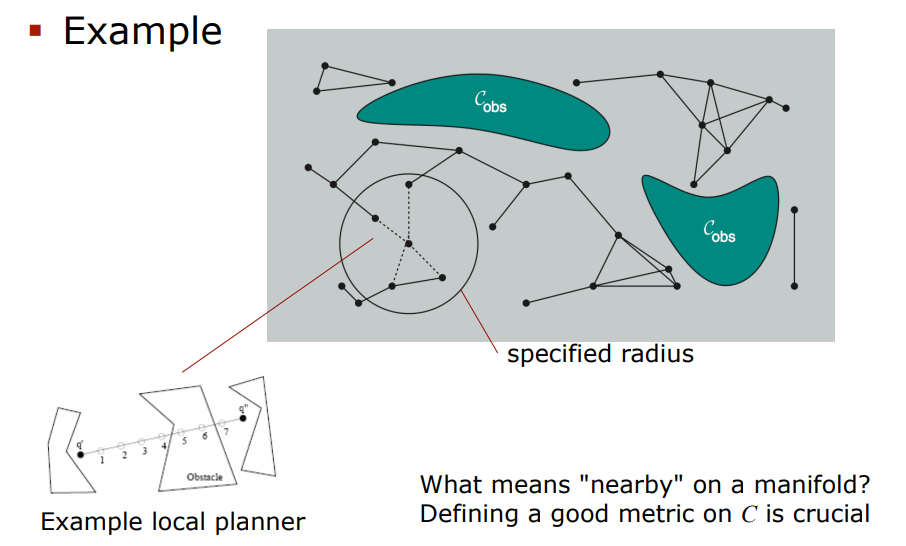
Probabilistic Road Maps
Take random samples from C,
declare them as vertices if in C-free, try to
connect nearby vertices with local planner
The local planner checks if line-of-sight is
collision-free (powerful or simple methods)
Options for nearby: k-nearest neighbors
or all neighbors within specified radius
Configurations and connections are added
to graph until roadmap is dense enough
Do not construct C-space Do not work well for some problems, narrow passages
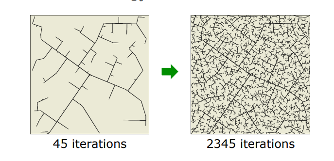
Rapidly Exploring Random Trees (RRT) :
The explored territory is marked by a
tree rooted at q0
Most modern-day planners use it, computational efficient.
planners are more efficient in most practical problems but offer weaker guarantees
They are probabilistically complete: the probability tends to 1 that a solution is found if one exists (otherwise it may still run forever)
Uninformed search
Informed search :
The problem of search: finding a sequence of actions (a path) that leads to desirable states (a goal)
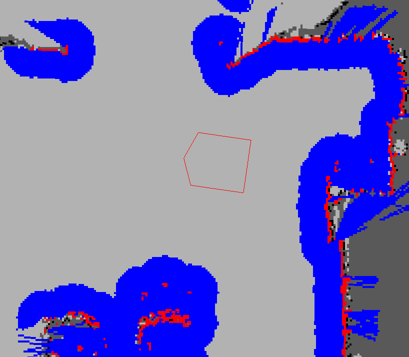
Source : http://wiki.ros.org/costmap_2d
Idea:
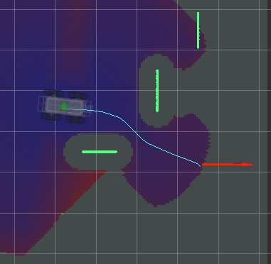
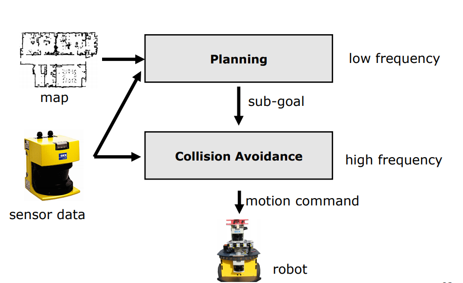
This can be handled by techniques called
collision avoidance (obstacle avoidance)
DWA approach :
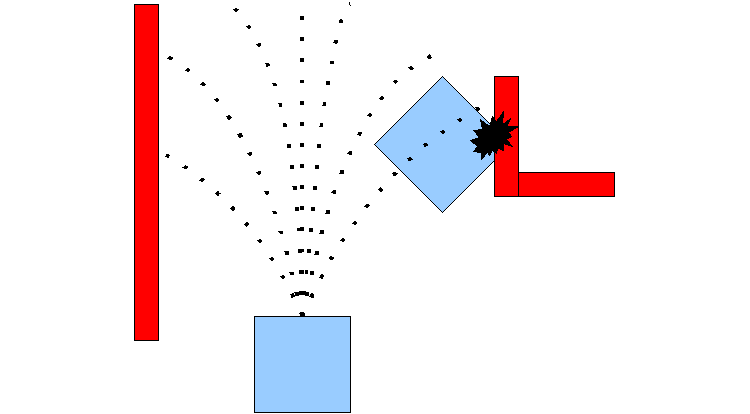
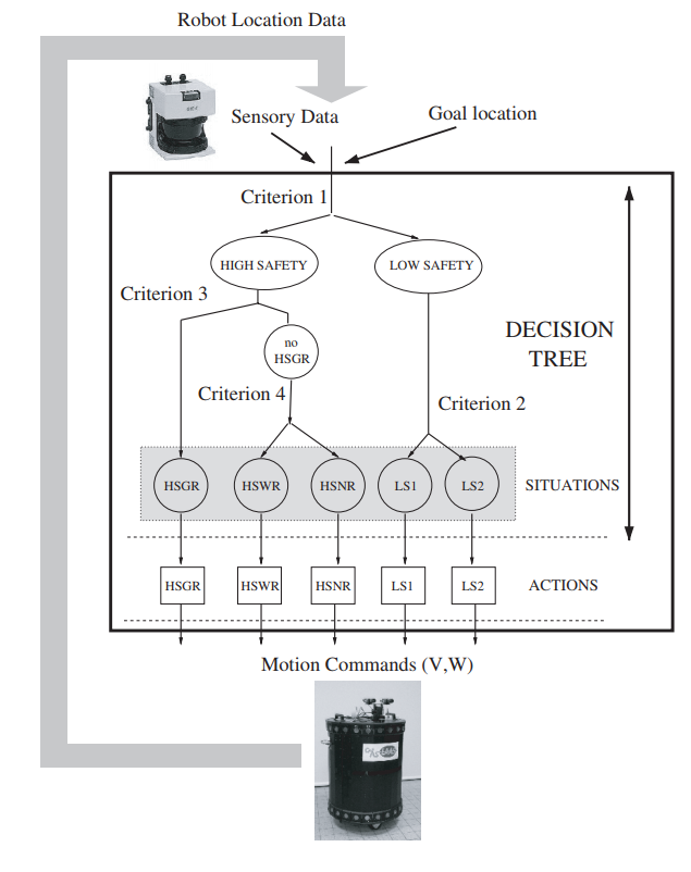
Nearest diagram approach :
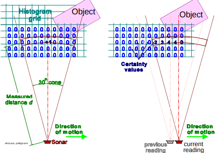
Vector Field Histogram:
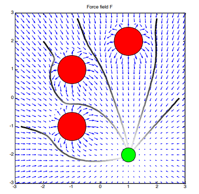
Extended potential Fields :
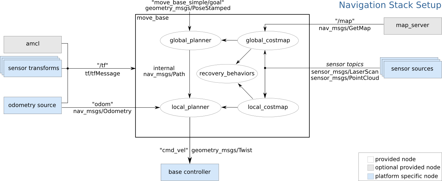
Source :http://wiki.ros.org/navigation
Source : http://wiki.ros.org/move_base
Modules integration for navigation
amcl :
Happy Navigating ..!
By Swapnil Kalhapure
Introduction to robot navigation