
"Propelling GCC towards greater achievements in the 21st century"
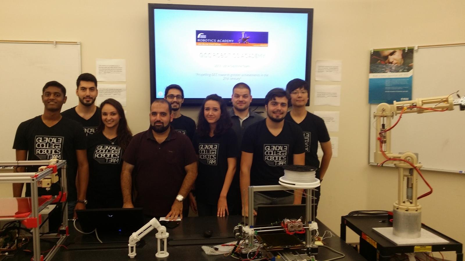
GCC Robotics Academy
2013 - 2014 Capstone Team
Capstone 2013-2014 Team
Outline
Vision
Mission
Goals
Approach
Organization
Results
Conclusion
Vision
Let's build something "legit"
Mission
Creating a team
Pursuing an opportunity
Goals
Specifics
Measurable
Achievable
Relevant
Timely
specifics
3D Printer
Robotic Arm Prometheus

measurable
Producing tangible results periodically
Achievable
Time management
Reasonably challenging projects
Passion
Mentor help
Relevant
Inter-disciplinary
Pertains to our studies at GCC
Enhancing our skill sets for internships/future jobs
Timely
-
Team Meetings: Every other Friday @ Noon
- Progress report
- Team coordination
- Goal Setting
- Sub-Teams had additional individual meetings

Approach
Active Learning by
Productive Struggle
- Research
- Reference Design: Bukobot
- Designing a New Printer
- Trial & Error
- Mentor/Team Support
Organization
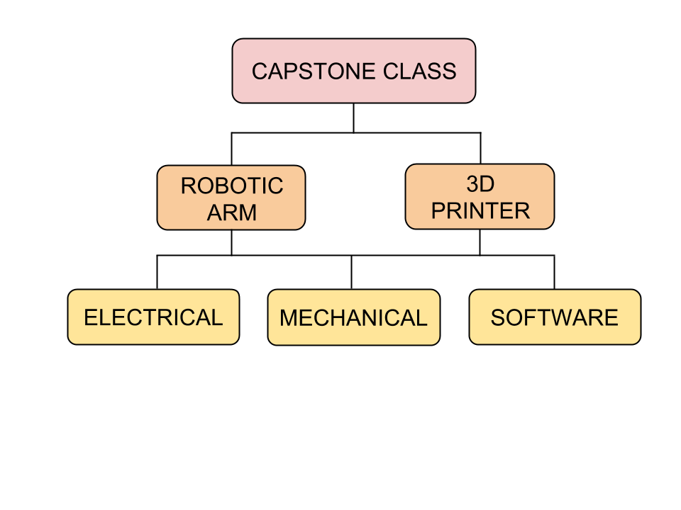
Challenges With Organization


Team Structure
Software
Mechanical
Electrical
Prometheus TEAM
E
A
M
T
3
3
D
P
R
I
N
T
E
R
PROCESSES
Self-Teaching
Communication
Leadership
Engaging GCC
Self-TEACHing
Experiencing New Tools
Experience by Trial & Error
Documentation
Communication
Leadership

Engaging GCC
Engaging Faculty
Inspiring Students
Results
Values Learned:
Leadership
Teamwork
Organization skill-set
Plan/Execute
Commitment
Time Management
Communication Platform/Skillset
Problem Solving
Abstraction
Engineering Skills
Technical Documentation
Presentation Skills
Leadership
Teamwork
Organization skill-set
Plan/Execute
Commitment
Time Management
Communication Platform/Skillset
Problem Solving
Abstraction
Engineering Skills
Technical Documentation
Presentation Skills
Conclusion
Special Thanks:
Technology & Aviation Division
Physical Sciences Division
Purchasing Office
GCC U.S. Department of Education Grants Team
BREAK!

GCC ROBOTICS ACADEMY
2013 - 2014 Capstone Team
CAPSTONE 2013-2014 TEAM

ROBOTIC ARM
3D PRINTER
Mission
Organization
Requirements
Mechanical Overview
Electrical Overview
Software Overview
Results
Requirements
Mechanical Overview
Electrical Overview
Software Overview
Outline
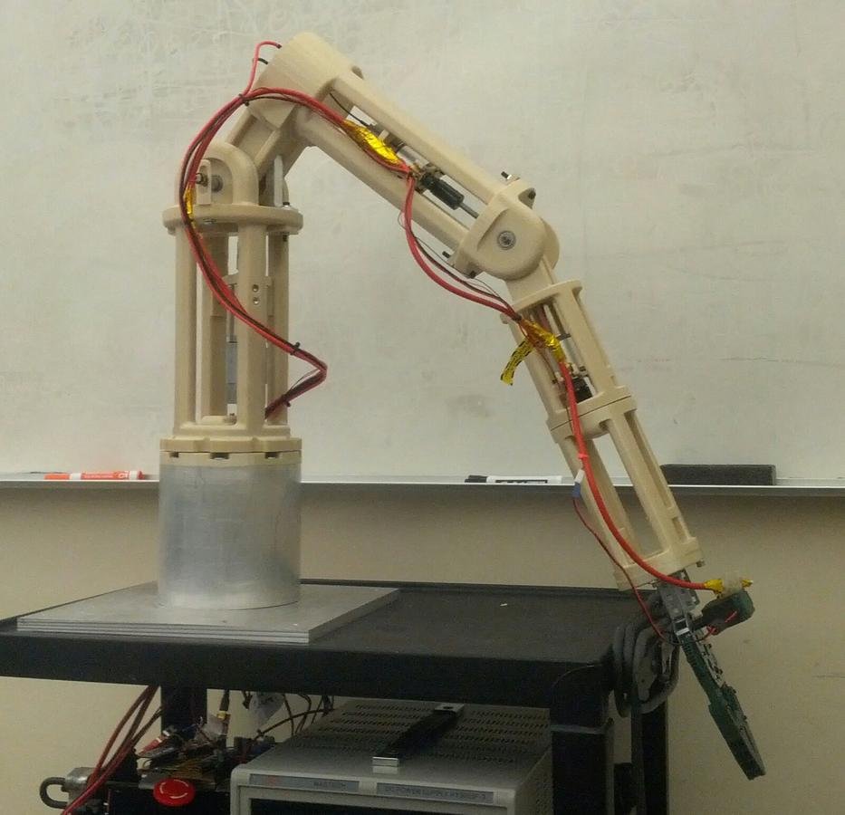
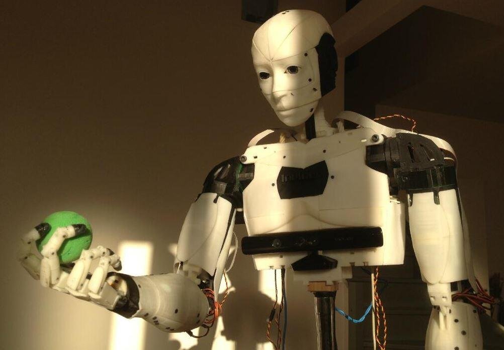
Prometheus
Project Overview
- The robotic arm - "Prometheus"
- Continued project from previous group
- Non-functional state
- All the code as well as electrical schematics and STLs for the 3D printed parts are available in the Github repositorygithub.com/gcc-robotics/prometheus
Organization
No formal organization due to small team size
Assistance from previous group members
and Capstone Project Mentors
Requirements
Meowchanical Overview
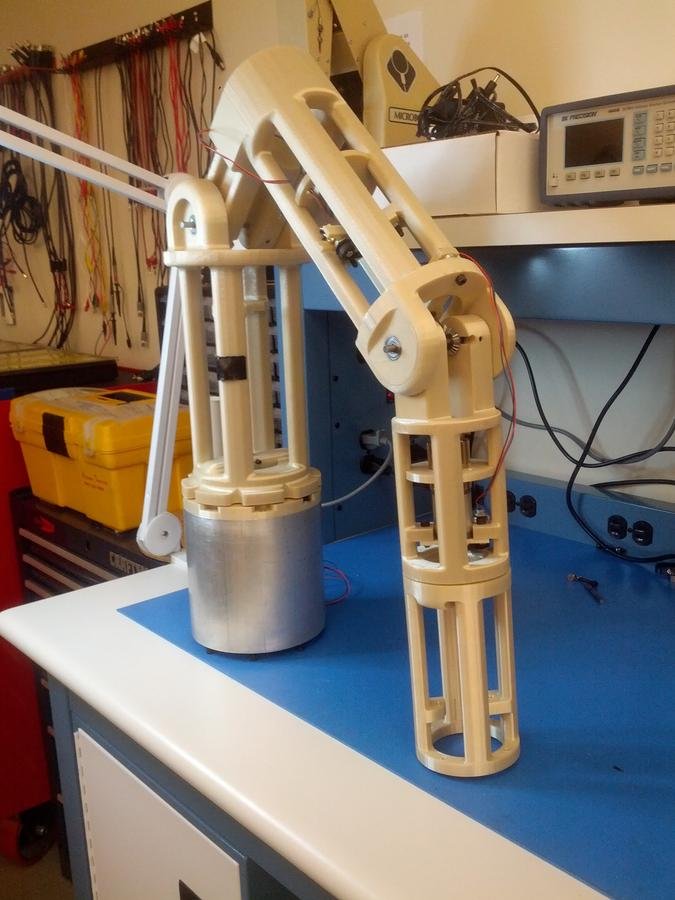
Robotic Arm

Robotic Arm
-Designed in Solidworks and 3D printed in Ultem
-Moving joints: Base, Shoulder, Elbow, Forearm, Claw
-Joint mechanics include: Bevel Gears, Worm drives, Direct Shaft Drives and Servo's
The process
-
Identifying existing problems
- Designing solutions
- Executing the solution


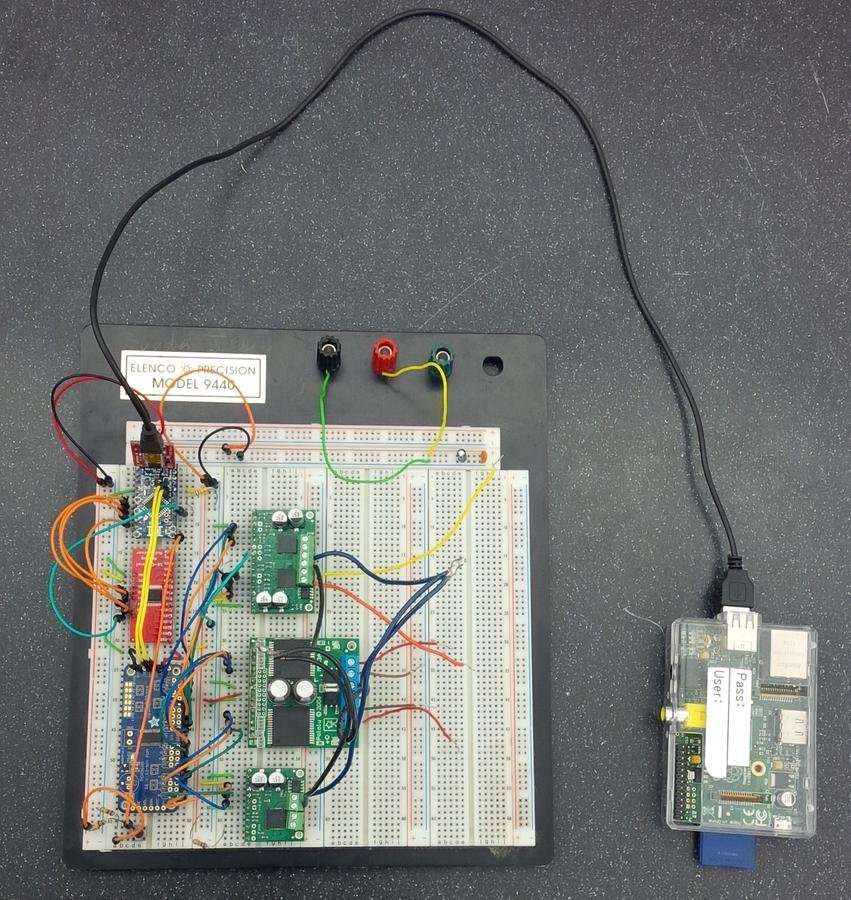
Electrical overview
Full schematic diagram
Block diagram
arduino pro mini
ARduino pro Mini
- Breakout board of the Atmega 329
- 5V 16MHz version
- Atmega 329
- Reset push-button
- Indicator LED
- Communication
- I2C
-
SPI
PWM generator
- Adafruit breakout board - PCA9685PW
- Communicates with Arduino via I2C communication port
- 16 individual outputs which are ordered into triplets: 2 control signals, 1 PWM signal
- Control signals govern motor direction and "braking"
- All outputs are 5 V logical signals
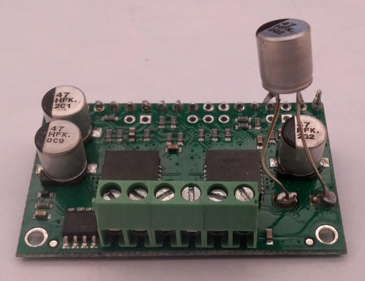
Motor drivers
- Convert 5 V Logical signals to high current 12 V drive signals
- Control signals are not amplified
- VNH2SP30 - dual H-Bridge motor driver carrier
- capable of supplying 30A of current to the motors
- MC33926 - standard H-Bridge motor driver carrier
- capable of supplying 3A (5A peak) of current to the motors
Encoders
- Absolute, Analog Voltage, Continuous Rotation
- 0 V to 5 V
-
Voltage directly proportional to angular position of encoder shaft
Multiplexer
- CD74HC4067 - 4 bit, 16 input multiplexer
- Multiplexes or "converges" 5 independent encoder signal inputs into one output pin
- Reduces number of Analog pins required on the microcontroller
- Each input from 0 to 15 corresponds to a 4 bit binary address
the Claaaw
- VEX Robotics kit component
- Low voltage motor can be run on 5V signal
-
Run with half L298 H-Bridge
Software overview
software map

- The control software for Prometheus
- 2 Microcontrollers
- Arduino - low level controls for the arm
- Raspberry Pi - higher level functions
- Communicate over Serial
Arduino software
- SistineChapel - Arduino Software
- motorController - lowest level of code and directly controls the in/out pins
- multiplexer - next level of code to control the multiplexer on the circuit board
- robotArm - contains the basic functions to control the movements of the arm
- PMotorSpeed - contains proportional calculations for the PID controller
- PIMotorSpeed - inherits PMotorSpeed class and contains integration calculations for the PID controller
- commandProcessor - communicates between the Arduino and Raspberry Pi
- debugger - test and debugging purposes
Raspberry Pi Software
- Narthex - Raspberry software
- Composed of two main parts
- Server side
- Client side
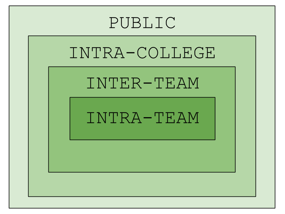
Narthex server side
- Narthex server side uses Python
- Bridges communication between the Arduino and the web interface
- Arduino -> Serial over USB
- Web Interface -> WebSocket
- Designed to handle multiple remote control interfaces at the same time
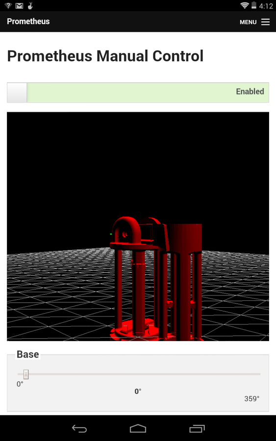
Narthex Client side
- HTML5 browser based interface
- 10.33.0.2
- Javascript for communication and 3D rendering
- Full 3D rendering
- PID tuning
- Debugging
Systems Challenges
- Communication
- even within smaller group difficulties were found communicating
- Meeting Times
- due to individual schedules being different, to accommodate time to meet was difficult
- Bill of Materials
- Inefficiency in placing orders
- Documentation
- Lack of documentation from previous group
- Current documentation is on Google Drive and being updated
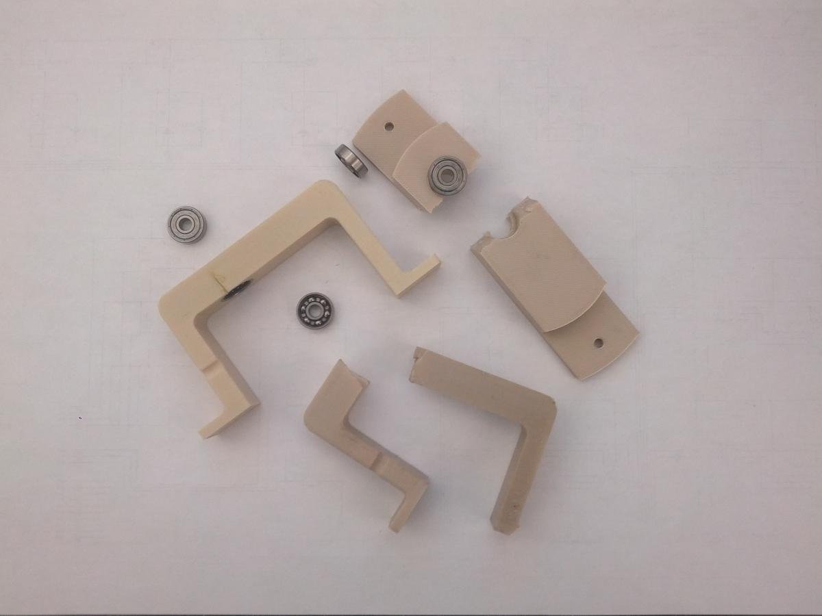
Mechanical Design Challenges

MECHANICAL DESIGN CHALLENGES
-Broken parts
-Unorganized drawing database
-Modifications made to parts without documentation
-Material costs
-Keeping the project within a reasonable budget
MECHANICAL DESIGN CHALLENGES
- Running into two additional problems after solving one
- Using as much of the existing structure as possible to keep costs reasonable
- Collateral damage from failing parts
Electrical DESIGN CHALLENGES
position
- Encoder readings inaccurate
- Arduino appeared to never read the full range of the analog encoder
- The incoming signal never reached 0V or 5V
- Encoder value is measured by the Arduino with an Analog to Digital Converter (ADC)
- ADC Type : Sample and Hold
- Key Concept of ADC Type : Successive Approximation
- Key Electrical Components : Input Capacitor and large series resistor
- ADC Resolution is 10 bit
- 1024 possibilities (5V/1024)
- Resolution is 0.0048828 V / bit
ADC input

- Capacitor Charges to VIN
- Capacitor Charge Time tau = R*C
- Atmel datasheet reports input capacitor 14pF, and series resistor 100M Ohm
- t = 0.0014 S
- @ t, VC = 63.2% VIN
- @ 5t, VC = 99.3% VIN, 5t = 7 mS
- Capacitor cannot reach 100% VIN
- Given ADC resolution of 0.0048828 V/bit , closest approximation of VC = 99.98% VIN = 1024
ADC Input
- Capacitor takes 7 mS to reach 99.3% VIN
- Arduino frequency is 16MHz (62.5 nS / Ass'y Instruction)
- 112,000 Assembly Instructions
- Microcontroller checks input voltage too early
-
Capacitor does not have sufficient time to charge up to 99.98% capacity
Software DESIGN CHALLENGES
Arduino Challenges
- Difficulty achieving precise movement
- Vex Claw support is hacked together
- Implementing the derivatives in PIDs
- Choice of microcontroller
Raspberry Pi Challenges
- The web client is not fully tested and has several issues remaining
- Features for multi-client syncing have been built but are not finished
- Remote control interface does not take collision detection into account
- Difficult to control for inexperienced
Mechanical Future Plan
Future plans
- Complete and design end-effector
- Remove slop from remaining joints
- Redesign damaged parts
- Use stepper motors
Electrical Future plans
Future plans
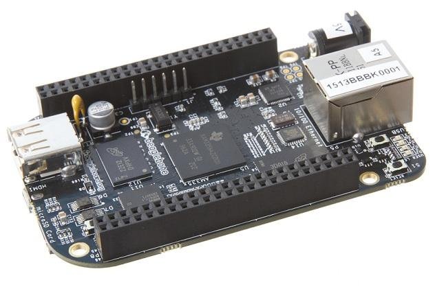
- The electronics will switch from Arduino to the Beaglebone Black
- multiplexer and PWM generator will be unnecessary
- encoders will connect directly to the Beaglebone Black along with motor drivers
- The arm will have an independent power supply
- Pressure sensor will be added for grip measurement and control
- Emergency stop
- Add end stops
- Convert to independent Delta Sigma ADC for faster conversion
Software future plans
Potential solutions
- Use stepper motors to allow for precise movement
- The communication and microcontroller limitations will be resolved by using a new microcontroller
- Collision detection will be handled by ROS
Future Plans
- Change microcontrollers
- Arduino + RaspberryPi -> BeagleBone Black
- Install ROS on new microcontroller
- Use ROS collision detection and inverse kinematics libraries
- Rewrite control code
- Develop speed controllers that handle dynamic loads
Results
Working
Robotic
Arm
Robotic
Arm
Mentors
Program Director: Voden, Tom
Mechanical Mentor: Toorian, Armen
Electrical Mentor: Ohanian, Richard
Software Mentor: Isayan, Sevada
Student Mentor: Pailevanian, Torkom
Mechanical Mentor: Toorian, Armen
Electrical Mentor: Ohanian, Richard
Software Mentor: Isayan, Sevada
Student Mentor: Pailevanian, Torkom
credit
Mechanical:
Zograbian, Roman
Electrical:
Hovhannisyan, Ernest
Software:
Kim, Sung Hoon
Litomisky, Marek
3D-Printer

Mission
Duplicate functionality of 3D printer used to construct arm parts
organization
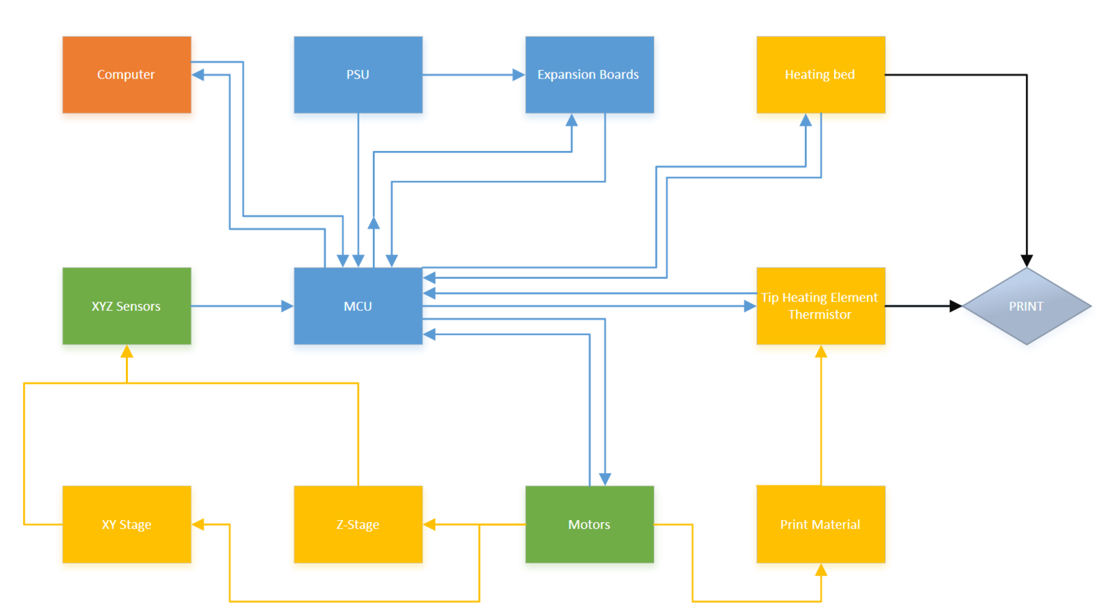
Functional Block Diagram
Comparison
Technical Timeline
Functional Block Diagram: Printer
Mechanical
Electrical
Electrical and Mechanical
Software
3d Printers: Comparison

|

|
| Enterprise | Hobbyist |
| $30,000-$250,000+ | $700-$2,500 |
| Propietary Materials | Universal Materials |
Requirements
-
Visually appealing
-
Modular
-
24" x 24" x 20"
-
Print volume maximized
-
Print various materials
-
Dual extruders, capable of independent motion
-
Capable of cooling the bed
REQUIREMENTS (CONT.)
Engineering Approaches
- Mechanical Team
- Prototype and Revise
- Electrical Team
- Replicate Functionality and Improve
- Software Team
- Expand on Mature Codebase
mechanical Overview
THE TEAM
Atkinson, John Paul
-Major: Mechanical Engineering
Khajatourians, Rene
-Major: Aerospace Engineering
Talverdian, Tamara
-Team Lead
-Major: Mechanical Engineering
Preparation
Research
Learning to Design
Buying/Building a Printer Kit
Testing the Printer
Deciding Features to Improve
purchasing
-
Finding necessary parts
-
Cost efficiency
-
Defining quantities
- Compiling Bill of Materials
-
Placing orders in a timely maner
Design
-
Using computer aided design tools
-
Dimensioning custom parts
-
Considering size expansion
-
Improving stability
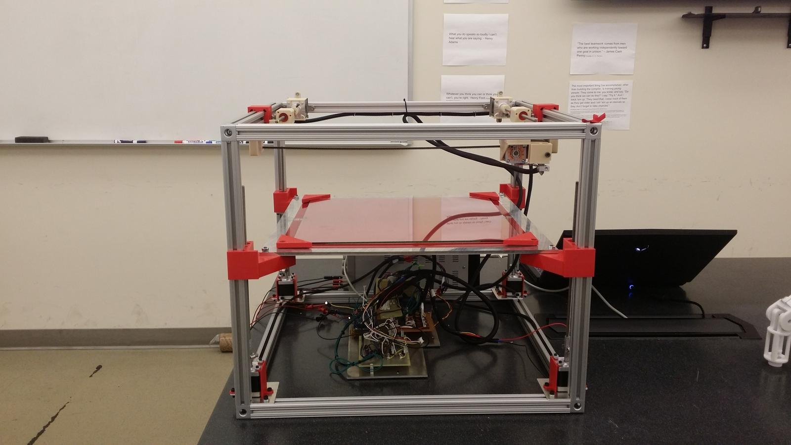
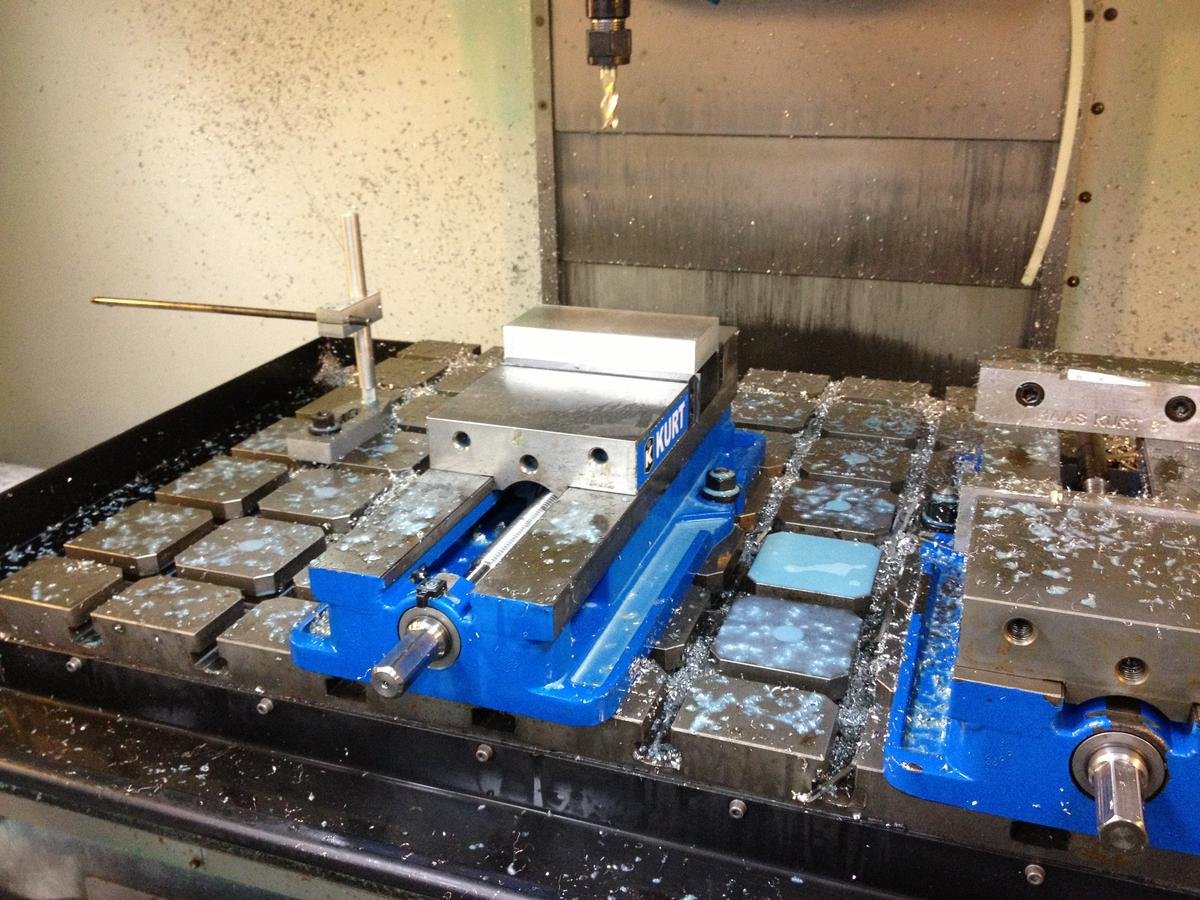
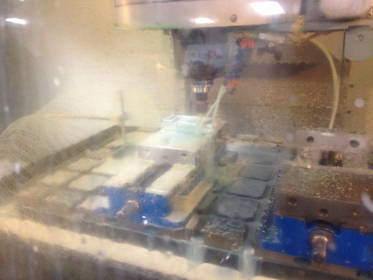
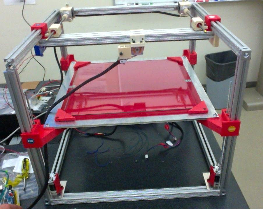
manufacturing
Technical
Structure
Motion
Heat Bed
Extruders
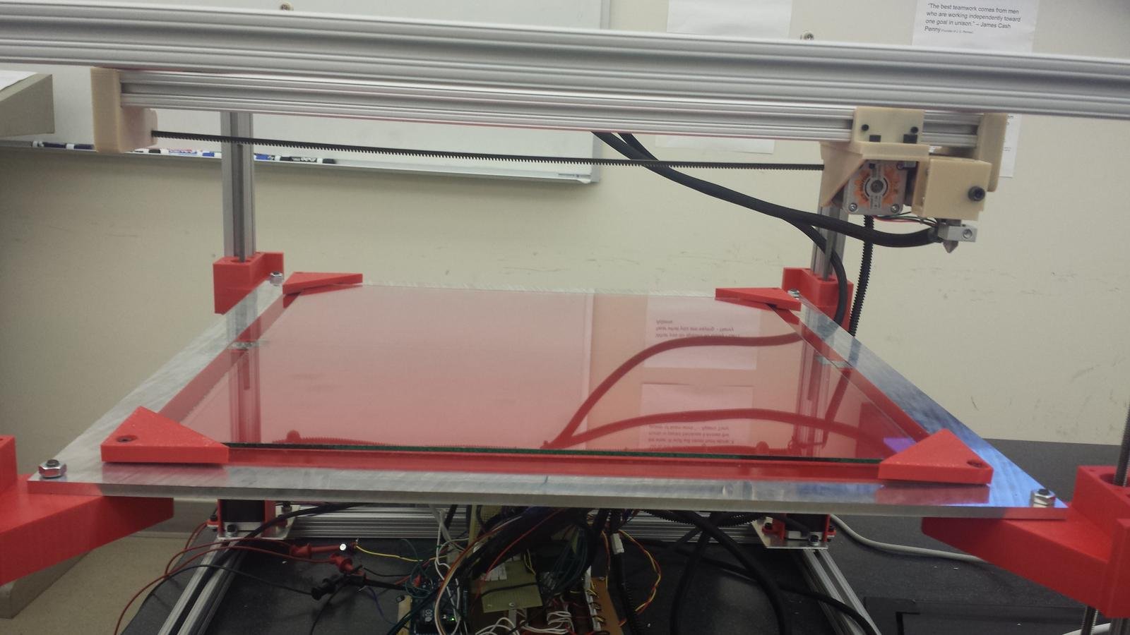
Structure


Structure

Components:
- Single Beam
- 1"x1"x18"
- 1"x1"x22"
- Double beam
- 2"x1"x24"
- Corner Connectors
Motion
Motors
Z-Axis
Y-Axis
X-Axis
Motors
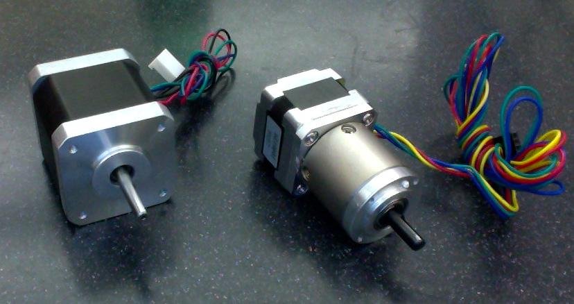
Motors
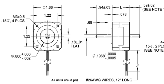
Axis Motors
-
Anaheim Automation
-
Nema 17
-
Length: 1.87 in
-
Lead wires: 4
-
Using: 8
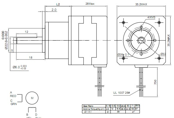
Extruder Motors
-
Kysan Electronics
-
Includes gear box
-
Length: 28+47mm
-
Lead wires: 4
-
Using: 2
x-Axis
Fastened to Y-axis
Driven by rack and pinion system
Two individual motors for each extruder

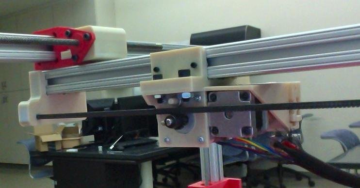
y-Axis
- Initial design: Belt drive system
- Changed to same drive system as Z-axis
- Driven by 2 motors
- Zero-Backlash nut

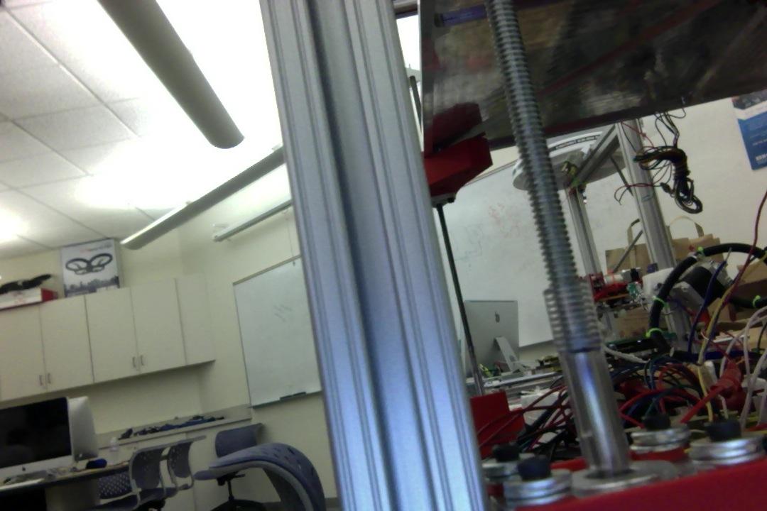
Z-Axis
Integrated into the structure.
- Custom 3D printed linear guide.
- Driven by lead screw/worm gear-nut system.
- Driven by 4 motors
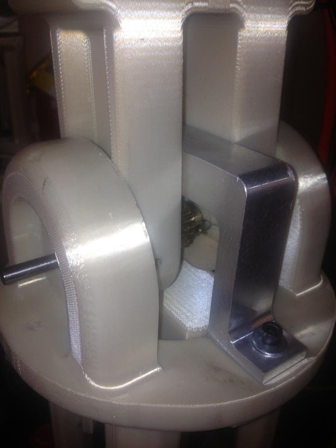
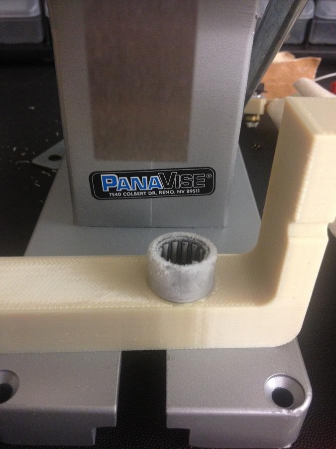
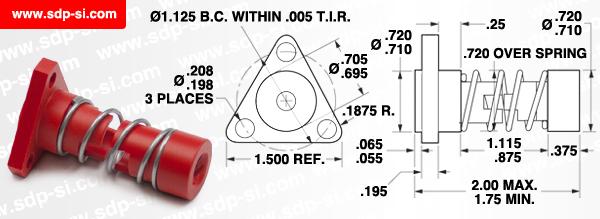
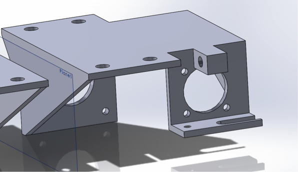
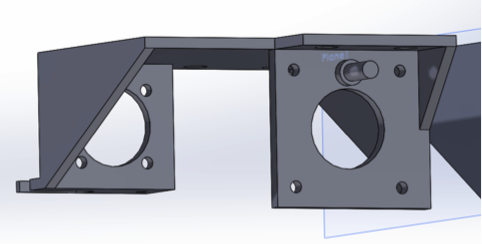
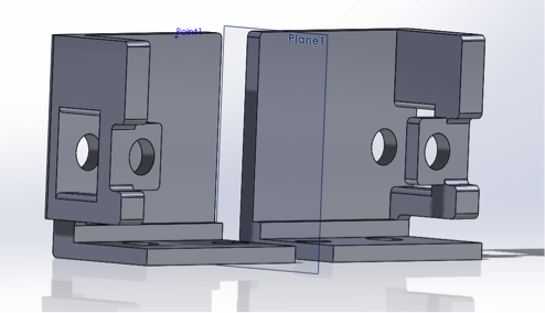
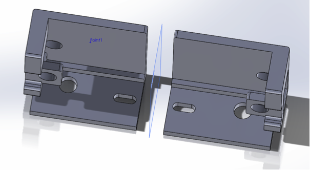
Custom Linear Guides
McMaster's Custom Design


Z-Axis
Z-Axis
Lead Screw/nut system
- 1/4"-20 Lead screw
- Coupled to motor using plastic hose
- Nut: Printed and tapped

Heat Bed
heat bed
Components:
- Heat sensor
- Glass w/ clamps
-
Heat bed
-
Aluminum plate
- TEC
-
Heat sink
-
Fan
Motion:
-
Z-axis

Extruders
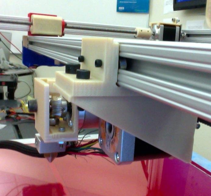
extruders
Components:
-
Extruder carriage
-
Lock Mechanism
-
Brass barrel
-
Resistor Block
-
Nozzle
Motion:
-
X-axis
-
Feeds filament
testing
Trial & Error
Challenges
-
Learning Essential Software
-
Time Constraints
-
Binding of Mounts
-
Accounting for Tolerances
-
Finding Specific Parts
-
Incorrect Parts Ordered
-
Manufacturing Defects
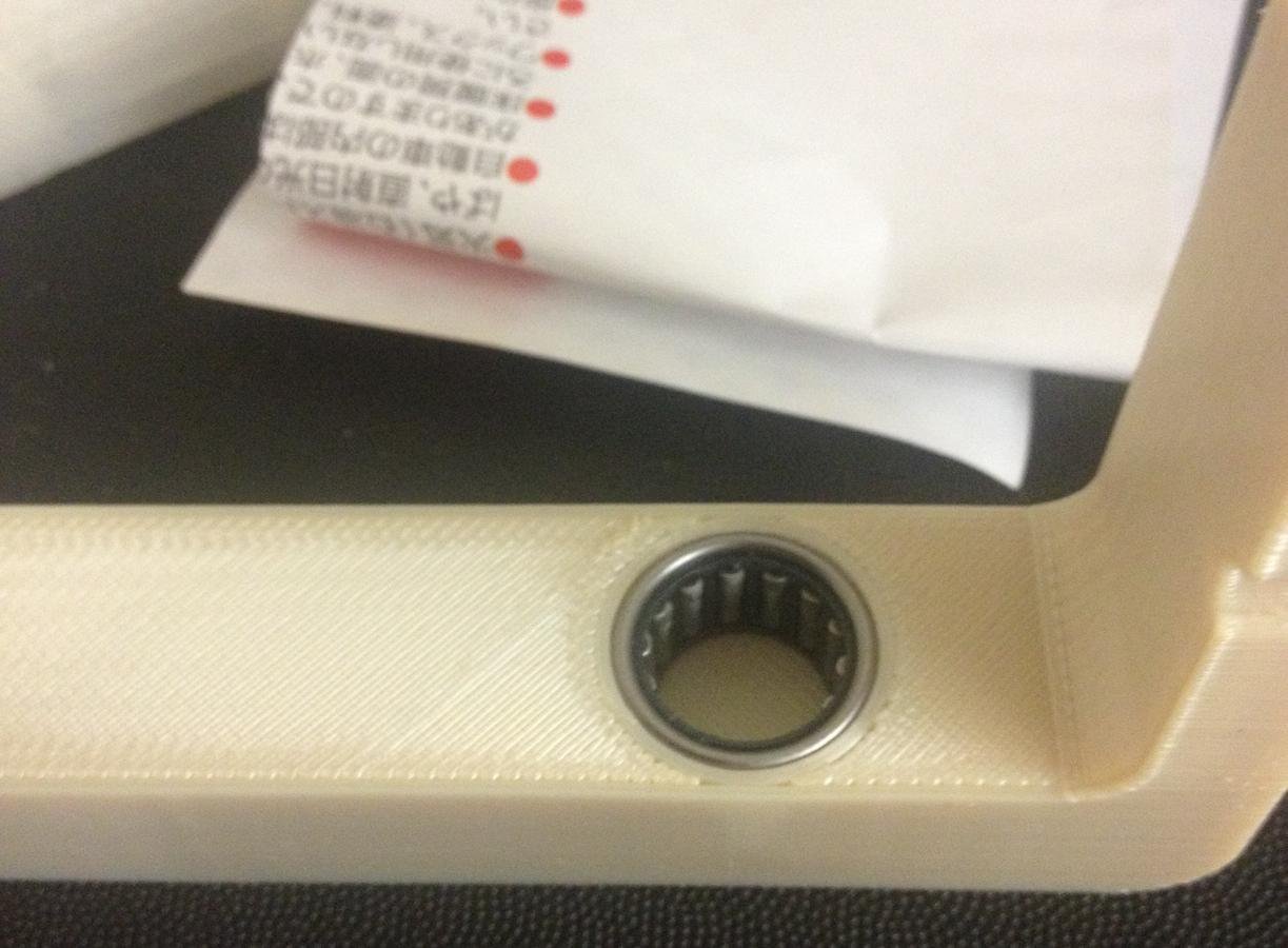
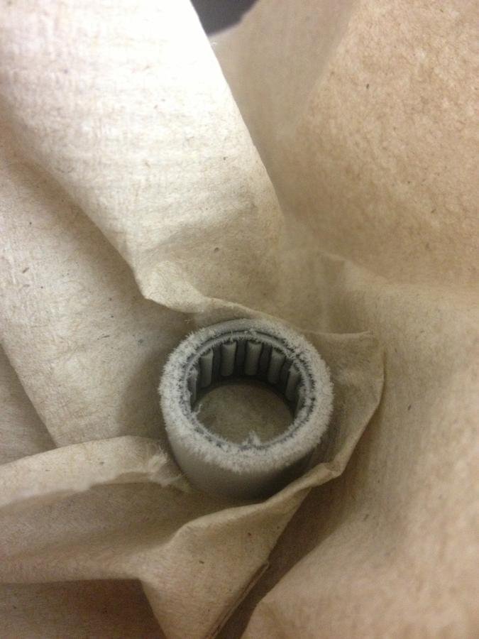
Continuous progress
Add linear bearings
More efficient guide design
Change Y-Axis motion system
Complete bill of materials for future purchasing/building
More efficient guide design
Change Y-Axis motion system
Complete bill of materials for future purchasing/building
Electrical Overview
THE TEAM

Hovhannisyan, Ernest
-Team Lead
-Major: Electrical Engineering
Kim, Sung Hoon
-Major: Computer Science/Engineering
Safarian, Vivian
-Major: Electrical Engineering
Preparation
-Research
-Gen6 Board
-Gen7 Schematic
Research
- Every Friday, compiled & presented ppt slides about topics
- Digital vs Analog
- Microcontrollers
- Rep-Rap
-
Main source of information and inspiration
Gen6 Board
- Prebuilt, predesigned board
- Ready to print during time of purchase
- No heated bed support
- Single extruder
- Tested for better understanding of its functionality
Gen7 schematics
- Primary source of design
- Used Atmega 1284
- Single Extruder
-
Supports heated bed
Purchasing
- Compiling Bill of Materials
- Selecting components that meet specifications
- Defining quantities
- Learning the importance of submitting in a timely matter
Design
-Old vs New Schematic Diagrams
-Block Diagram
Original schematic
New schematic
Block Diagram
the build
-Microcontroller
-Motor Drivers
-Heaters & Fans
ATmega 2560
- Microcontroller board based on the ATmega2560
16 MHz crystal oscillator
USB connection
ICSP header
Reset Button
atmega 2560
-
Power
- Can be powered via USB connection or with an external power supply
- Our board will be supplied with power from the USB connector (5V)
- Power pins:
- Input voltages are regulated to 5V
- GND. Ground pins
Atmega 2560
- Mega2560 Input/Output
- 54 digital pins
- can be used as I/O
-
16 analog inputs
ENDSTOPS
- Mechanical endstop
- using 4
- 2 for x-axis, 1 for y-axis, 1 for z-axis
- Purpose:
- Designates the origin of the coordinate system
- Connected directly to Arduino
- one line to 5V, other to digital pins
L297 & L298
- L297
- L297 Stepper motor controller IC
- Step and Direction Translator
- bipolar stepper motors
- single winding per phase
- Requires only clock & direction signals
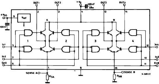
- L298
- High voltage, high current motor driver
- Designed to accept L297 signals
allegro Stepper Motor Driver
- A-4988 board
- Step and direction pins will communicate with the Atmega 2560
- 6 motor drivers:
- 2 x-axis
- 2 extruders
- 1 y-axis
- 2 z-axis
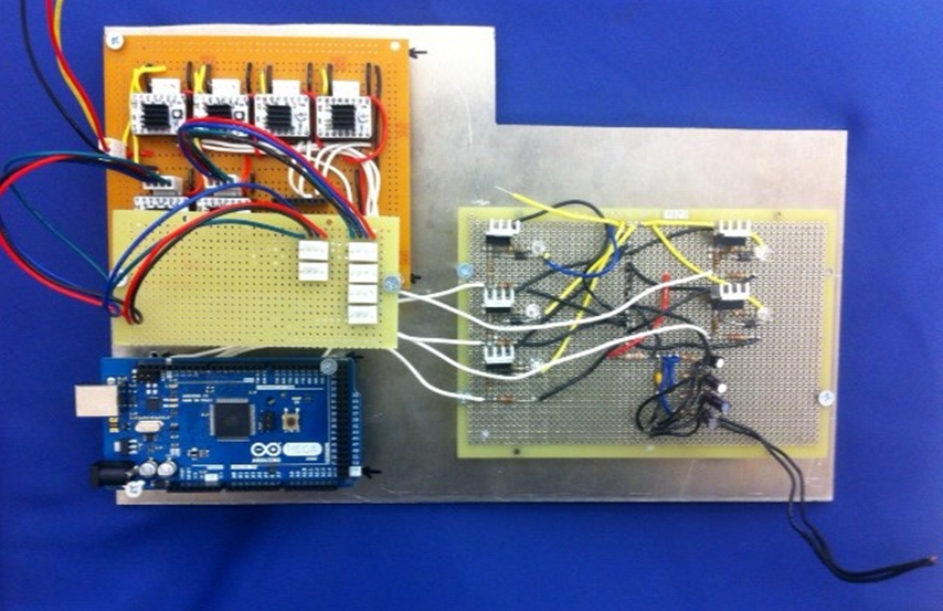
Our Motor Driver board
temperature
- Heater Bed
- Peltier Plate (TEC)
- Cools heat bed, requires 3 Amps
- Heater and Thermistor Board
- Heat up extruders, TEC place, & control the fans
- Measure temperatures of 2 extruders & electronics area for safety
heater bed
- Etched PCB Resistive heater
- Calculated current of 45 A
- Driven by MOSFET
- Requires independent PCB with large surface area of copper to supply sufficient current
- Requires larger flyback diode
tec and block
- TEC
- 3 Amps max power
- Engaged when print job is finished
- Heater Block
- Resistive heater
- 3 Amps max power
Temperature sensor
- 10k Ohm Thermistor
- NTC Type
- Non-linear temperature vs. resistance curve
- Requires 5 V Analog Voltage and GND
H &T Board
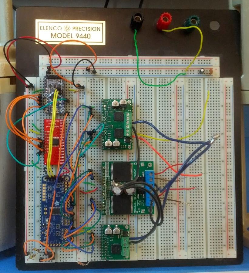
prototyping
-Equipment
-Process
-Testing
-Documentation
Equipment
- Digital Multimeter
-
Oscilloscope
-
Function Generator
-
Soldering Station/Desoldering Station
-
Power Supply
-
Hot Air Station
Process
- Prototype board
- Solderless breadboards
- Future goal: plan and design a PCB
- neater, space reduction
TESTING
- Testing was done in modules
- Approach:
-
Tested each component by itself to make sure it's working properly
-
Tested as an individual circuit
- Tested as a system
DOcumentation
- Documented after every milestone
- Recorded progress in Electronics Guide
- most relevant/useful documentation transferred to Google Doc
-
Used Google Doc
- easy access and editing
- team was already acquainted with it
challenges/
Future progress
Software Overview

the team
Kim, Sung Hoon
-Major: Computer Science/Engineering
Litomisky, Marek
-The Big Cheese
-The Big Cheese
-Major: Computer Engineering/Magic
Design Goals
- Code was forked from ErikZalm/Marlin
- Added functions
- Dual independent extruder carriages
- Main focus
- Control movements in all axes with Repetier-Host software
- Ability to find the start position (origin) with endstops
Design Challenges
- Understanding massive starting code base
- Dozens of classes
- 30+ thousand lines of code
- Dual extruder carriage with independent movements
- Non-standard 3D printer feature
- Time constraints
Arduino Software
- Main focus was making basic features work with the new electronics
- Required through understanding the code base
- Researched independent dual X-axis carriage control
Testing Procedures
- Had difficulty testing as a system
- Requires a whole functional unit
- Began testing individually
- Wrote simple code to test individual components
- Tested modules as they were completed
Results
- All directions can be controlled through Repetier-Host software
- The movements are not completely correct
- Need to adjust feedrates, accelerations, steps per unit
- Need to consult the Mechanical team for hardware limitations
- The endstops do not correctly register when pressed
- Needs more investigation
Future Directions
- Main focus
- Defining all the settings to be in printable states
- Once all the settings are determined
- Emphasis will be on dual extruder independent movements
- Will require new way of testing due to Repetier-Host not having controls for 2nd extruder movement
- Refining settings to get more accurate printing
Results
Mentors
Program Director: Voden, Tom
Mechanical Mentor: Toorian, Armen
Electrical Mentor: Ohanian, Richard
Software Mentor: Isayan, Sevada
members
Mechanical Team:
Atkinson, John Paul
Khajatourians, Rene
Talverdian, Tamara
Atkinson, John Paul
Khajatourians, Rene
Talverdian, Tamara
Electrical Team:
Hovhannisyan, Ernest
Kim, Sung Hoon
Safarian, Vivian
Hovhannisyan, Ernest
Kim, Sung Hoon
Safarian, Vivian
Software Team:
Kim, Sung Hoon
Litomisky, Marek
Kim, Sung Hoon
Litomisky, Marek
Systems:
Saleebyan, Skyler
Saleebyan, Skyler
question & answer
GCC Capstone Project
By sungkim7790


