
Prometheus
2013 - 2014
Outline
- Goals
- Team
- Mechanical
- Electronics
- Software
- Demo
-
Issues
Systems overview
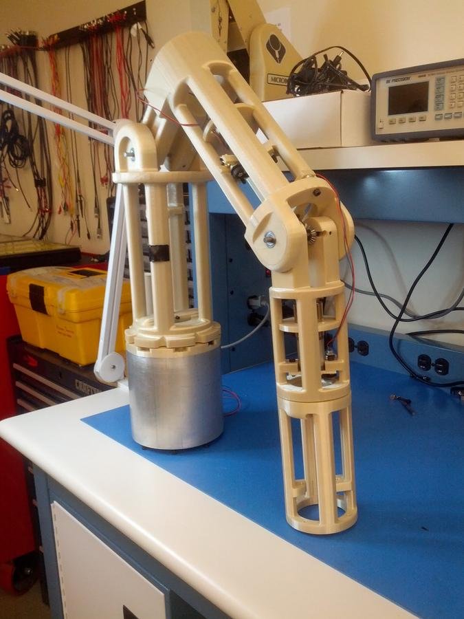
- The robot arm - "Prometheus"
- Inherited the project from last year
- All the codes as well as electrical schematics and STLs for the 3D printed parts are available in the Github repository
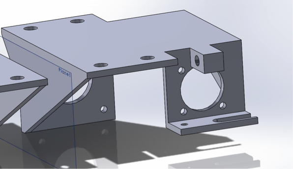
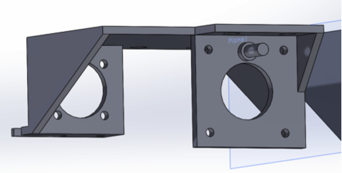
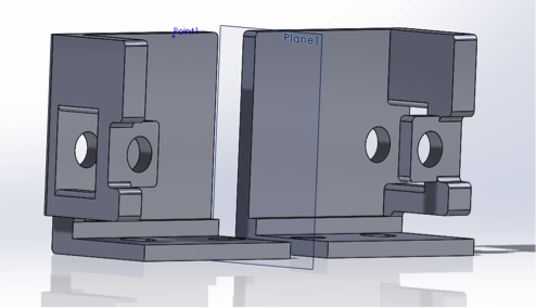
Mechanical Overview
Robotic Arm
Electrical overview
Full schematic diagram

Title

arduino pro mini

ARduino pro Mini
- Breakout board of the Atmega 329
- 5V 16MHz version
- Atmega 329
- 16MHz crystal oscillator
- 3.3V voltage regulator
- Reset push-button
- Indicator LED
Arduino pro Mini pin FUNCTIONS
- Arduino pro mini contains 13 digital pins and 4 analog pins
- digital pins receive and transmit information in binary form
- analog pins feed into 10-bit analog to digital converter, and read a voltage from 0V to 5V
Arduino mini pro communication
- Two methods of communication
- SPI bus
- reserved for USB communication
-
I2C bus
- requires one device to be set as the Master and subsequent devices to be set as slaves
- occupied by the PWM generator
PWM generator
- Adafruit breakout board - PCA9685PW
- requires 5V power and ground and standard two wire I2C communication port
- 16 individual outputs which are ordered into triplets: 2 control signal, 1 PWM signal
- 2 control signal - directional/control outputs
VNH2sp30

MC33926

Motor drivers
- VNH2SP30 - dual H-Bridge motor driver carrier
- capable of supplying 30A of current to the motors
- MC33926 - standard H-Bridge motor driver carrier
- capable of supplying 3A (5A peak) of current to the motors
Encoders
- The arm requires 5 encoders
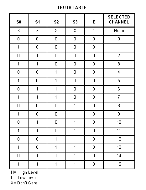
Multiplexer
- CD74HC4067 - 4 bit, 16 input multiplexer
- Each input from 0 to 15 corresponds to a 4 bit binary address
Multiplexer truth table
Software overview
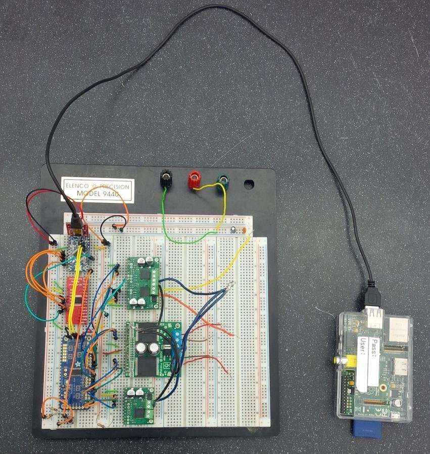
software map

- The control software for Prometheus
- 2 Microcontrollers
- Arduino - low level controls for the arm
- Raspberry Pi - higher level functions
- Communicate over Serial
Arduino Software

Arduino software
- SistineChapel - Arduino Software
- motorController - lowest level of code and directly controls the in/out pins
- multiplexer - next level of code to control the multiplexer on the circuit board
- robotArm - contains the basic functions to control the movements of the arm
- PMotorSpeed - contains proportional calculations for the PID controller
- PIMotorSpeed - inherits PMotorSpeed class and contains integration calculations for the PID controller
- commandProcessor - communicates between the Arduino and Raspberry Pi
- debugger - test and debugging purposes
Raspberry Pi Software Map

Raspberry Pi Software
- Narthex - Raspberry software
- Narthex - composed of two main parts
- Server side
- Client side
Narthex server side
- Narthex server side uses Python
- Utilizes the Twisted even driven networking engine
- Narthex server sides forms a bridge to allow communication between the Arduino and the remote control interface
- Communicates with the Arduino using Serial over USB
- Server side has three main parts:
- server.py
- The main program which runs all the other portions of the code
- PrometheusSerial.py
- handles communication with the Arduino
- PrometheusSocket.py
- Handles communication with the remote control interface
- Narthex is designed to handle multiple remote control interfaces at the same time
Narthex Client side
- The client side served to the users' browsers when they point it the IP or the Raspberry Pi
- 10.33.0.2
- The webpage contains Javascript
- Provides communication with the server side and the Arduinio
- The interface makes use of serveral 3rd party javascript libraries
- three.js
- Provides the 3D rendering of the arm to give the user visual
- knockout.js
- Provides two-way synchronization between the Javascript data models and the user interface
Systems Challenges
- Communication - even within smaller group difficulties were found communicating
- Arranging time for meeting - due to individual schedules being different, to accommodate time to meet was difficult
Mechanical Design Challenges
Electrical DESIGN CHALLENGES
Title
- Fundamental design of the circuitry is inherently flawed
- Arduino appeared to never read the full range of the analog encoder
- The incoming signal never reached 0V or 5V
- The source of the problem is due to the type of ADC on the ATMEGA328 chip

Title
- The I2C bus is a serial port which adds a delay between commands and motion
- The multiplexer adds on through its propagation delay
- The multiplexer adds unecessary resistance to the encoder voltage
Software DESIGN CHALLENGES
Arduino Challenges
- The motorController class requires modification of the speed function
- The robotArm class contains low level codes to directly communicate with in/out pins
- PMotorSpeed, PIMotorSpeed classes both require tuning of proportional and integral terms for more accuracy
- PIDMotorSpeed is not complete and also would require tuning
- commandProcessor class does not have any problem on the software side; however, due to hardware limitations
Raspberry Pi Challenges
- The client side of the Narthex code is not completely tested and has several issues
- The remote control interface does not correctly read the joint limits
- Features for multi-client syncing have been build into Narthex but are not finished
- Remote control interface does not take collision detection into account
- The remote control interface also does not read the setpoints from the Arduino when it is first started
Mechanical Future Plan
Future plans
- Complete and design end effector
- Remove slop from remaining joints
- Redesign damaged parts
Electrical Future plans
Future plans
- The electronics will switch from Arduino to the Beaglebone Black
- multiplexer and PWM generator will be unnecessary
- encoders will connect directly to the Beaglebone Black along with motor drivers
- The arm will have an independent power supply
- Pressure sensor will be added for grip measurement and control
- Emergency stop
Software future plans
Potential solutions
- The solution to control the speed of the motors is not yet figured out and will be one of the criteria for the future work
- The direct communication between the in/out pins and the arduino is temporary and will be abstracted away
- PID controller will require tuning and this can be done through series of testing and calculations
- The issue found in communicating between arduino and raspberry pi will be addressed by change in hardware
Future Plans
- Hardware change
- In version 2, arduino and raspberry pi will be replaced by single board, Beaglebone Black
- With the change in hardware, the software team can integrate ROS and their inverse kinematics libraries
- The software team will rewrite the code in order to run Prometheus with this new Beaglebone Black
- PID controller requires coding to accommodate the new board
- Once the PID controller codes are written, the software team needs to tune the PID in order to minimize the errors
Demo
Question & Answer
credit
- Capstone Advisor: Voden, Tom
- Mechanical Mentor: Toorian, Armen
- Electrical Mentor: Ohanian, Richard
- Software Mentor: Isayan, Sevada
- Mechanical :
- Zograbian, Roman
- Electrical:
- Hovhannisyan, Ernest
- Software:
- Kim, Sung Hoon
- Litomisky, Marek
"G.O.D.D."
Presentation
2013 - 2014
Capstone 2013-2014 Team
PICTURE HERE DAWG
Outline
Decision
Organization
Requirements
Experience
Future Plans
Q&A
-----------------
Mechanical Overview
Electrical Overview
Software Overview
Q&A
3d Printer

|

|
| Enterprise | Hobbyist |
| ($30,000-$250,000+) | Cheap ($700-$2,500) |
| Propietary Materials | Universal Materials |
decision
Arm project used 3D-printed parts
New Technology
Equal distribution of mechanical, electrical, and software
skyler
Organization
Functional Block Diagram
Team Structure
3 Sub-Teams:
-
Mechanical
-
Electrical
-
Software
SChedule
Team Meetings: Every other Friday @ Noon
-
Progress check
-
Systems coordination
Sub-Teams had additional individual meetings
Requirements
-
Size: 24 x 24 x 18 inches
- Bed moving in Z-motion
-
Dual extruders; moving independently of one another
-
Strong frame
- Quality motion mechanisms
- Modular
mechanical Overview
Lionel, John Paul
-Major: Mechanical Engineering; CSU Northridge Transfer
Khatchatourians, Rene
-Major: Aerospace Engineering; CalPoly Pomona Transfer
Talverdian, Tamara
-Team Lead
-Major: Mechanical Engineering; CalPoly Pomona Transfer
Preparation
purchasing
Challenges:
Design
manufacturing
Technical


Structure
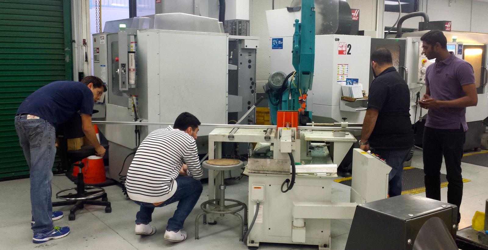
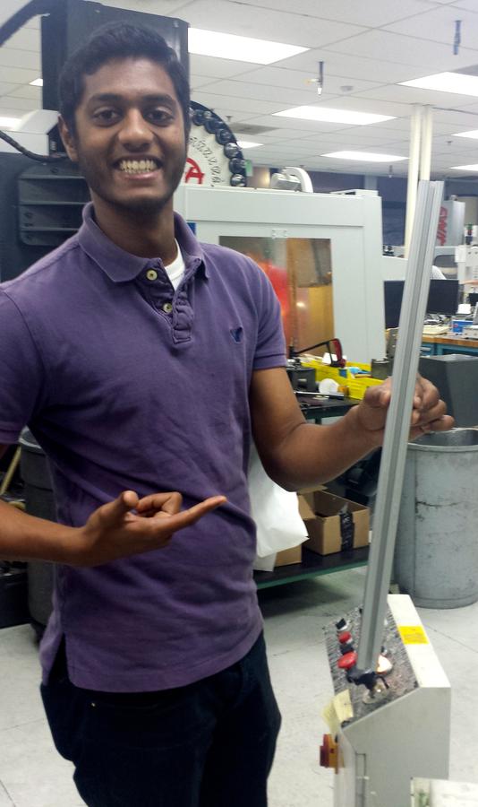
Based on 80/20 beams
Single Beam
1"x1"x18"
1"x1"x22"
Double beam
2"x1"x24"
- Corner Connectors.

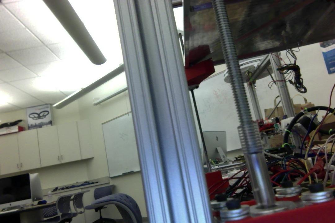
Structure

Z-Motion
Integrated into the structure.
- Custom 3D printed linear guide.
- Driven by lead screw/worm gear-nut system.
- Driven by 4 motors/2 motor drivers.
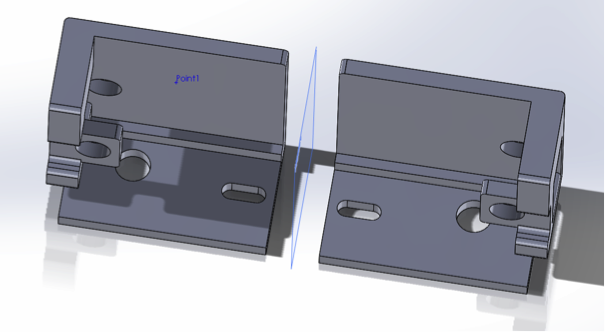
Custom Linear Guides
McMaster's Custom Design


Z-Motion
Z-motion
Lead Screw/nut system
- 1/4"-20 Lead screw
- Coupled to motor using plastic hose.
- Nut: Printed and tapped.

heat bed
Components:
- Heat sensor
- Glass w/ clamps
-
Heat bed
-
Aluminum plate
- TEC
-
Heat sink
-
Fan
Motion:
-
Z-axis


y-motion
- Initial design: Belt drive system.
- Changed to same drive system as Z-axis.
- Zero-Backlash nut.

x-motion
Moves with Y-axis
Driven by rack and pinion system
Two individual motors for each extruder
extruders
Components:
-
Extruder carriage
-
Lock Mechanism
-
Brass barrel
-
Resistor Block
-
Nozzle (.2, .3, and .4mm)
Motion:
-
X-axis
-
Feeds filament
testing
future work
More efficient sliding mount design
Complete bill of materials for future purchasing/building
Electrical Overview
the team
Hovhannisyan, Ernest
-Team Lead
-Major: Electrical Engineering; CalState LA Transfer
Kim, Sung Hoon
-Major: Computer Science/Engineering; 2nd Year GCC
Safarian, Vivian
-Major: Electrical Engineering; USC transfer
Preparation
-Research
-Gen6 Board
-Gen7 Schematic
PROduction methods
- Initially we directly soldered onto prototype boards
- boards did not work -->
- switched to using solderless breadboards for layout and testing
- minimized errors and number of boards/parts wasted
- Used perforated prototype board for final motor driver board & heater and temperature board
- Future goal: plan and design a PCB
- neater, physically more appealing, space reduction
production methods
solderless breadboard
prototype board


purchasing
-Compiling BOM's
Bill of materials
- Selecting components that meet specifications
- Defining quantities
- Learning the importance of submitting in a timely matter
Design
-Old vs New Schematic Diagrams
-Block Diagram
Design
- Learned to define specifications that will work with existing circuitry
Original schematic
New schematic
Block Diagram
Implementation
-Microcontroller
-Motor Drivers
-Heaters & Fans
atmega 2560
-
Power
- Can be powered via the USB connection or with an external power supply - we are connecting to a computer via USB to power
- Board has two voltage regulators: 5V & 3.3V
- The power pins:
- 5V. Outputs a regulated 5V from the regulator on board. Our board will be supplied with power from the USB connector (5V).
- 3V3. A 3.3 volt supply generated by the on-board regulator. Maximum current draw is 50 mA.
- GND. Ground pins.
ARDUINO mega 2560
- microcontroller board based on the ATmega2560
- It has 54 digital input/output pins & 16 analog inputs,
- 16 MHz crystal oscillator, a USB connection, a power jack, an ICSP header, and a reset button.
- The Mega2560 differs from does not use the FTDI USB-to-serial driver chip.
- Instead features the ATmega16U2 (ATmega8U2 in the revision 1 and revision 2 boards) programmed as a USB-to-serial converter.
Atmea 2560
- Input/Output
- Each of the 54 digital pins on the Mega can be used as an input or output, using pinMode(), digitalWrite(), and digitalRead() functions
- They operate at 5 volts
- Each pin can provide or receive a maximum of 40 mA and has an internal pull-up resistor
- The Mega2560 has 16 analog inputs
ENDSTOPS
- Mechanical endstop
- using 4
- 2 for x-axis, 1 for y-axis, 1 for z-axis
- Purpose:
- for software: by pressing the endstop, designates the origin of the coordinate system
- necessary because with the origin, cannot know/control where the motors are/go
- Connected directly to Arduino
- one line to 5V, other to digital pins on the Arduino
L297 & L298
- L297 Stepper motor controller IC generates four phase drive signals for two phase bipolar and four phase unipolar step motors
- Can be driven in half step, normal and wave drive modes
- Requires only clock, direction and mode input signals
- Can be used with monolithic bridge drives such as L298
- L298 is an integrated monolithic circuit
- It is high voltage, high current dual full-bridge driver
- Designed to accept standard TTL logic levels
- Two enable inputs are provided to enable or disable the device independently of the input signals
allegro Stepper Motor Driver
- A-4988 board
- each driver has step and direction pins which will communicate with the Atmega 2560
- Total of 6 motor drivers:
- 2 x-axis
- 2 independent motor drivers to control 2 separate motions
- 2 extruders
-
to print different materials
- 1 y-axis
- will drive 2 motors in parallel
- 2 z-axis
- will drive 2 motors in parallel per motor driver
- one signal is shared between the two motor drivers
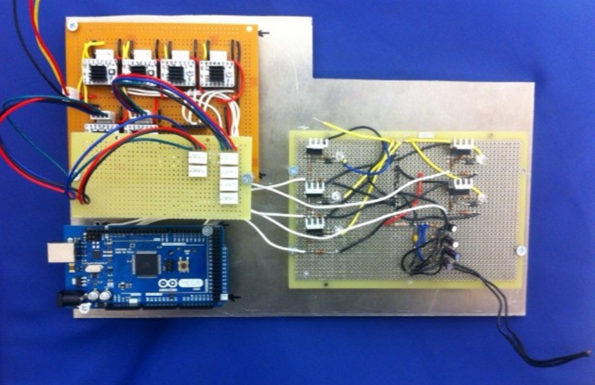
Our Motor Driver board
temperature
- Heater Bed
- Peltier Plate (TEC)
- Will cool heat bed, takes 3 amps
- Heater and Thermistor Board
- Function: heat up the extruders, TEC place, & control the fan
- 2nd Function: measure temperatures of 2 extruders and electronics area for safety
- Independent board to heat up as well as measure the temp. of the bed
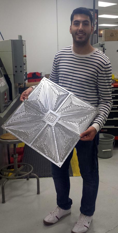
heater bed
- Etched PCB Resistive heater
- Designed for 12 V nominal power
- Calculated current of approximately 45 A
Peltier plate
- things and stuff
HEater block
- Resistive heater
- Standard Glow Plug
- 3 A max
Temperature sensor
- 10k Ohm Thermistor
- NTC Type
- max temperature
analog filter
H&T Board
prototyping
-Equipment
-Testing
-Documentation
Equipment
-
Digital Multimeter
-
Oscilloscope
-
Function Generator
-
Soldering Station/Desoldering Station
-
Power Supply
-
Hot Air Station
TESTING
- Testing was done in modules
- allows us to focus on one individual component at a time and identify errors more easily than if tested as a unit
- Approach:
1. Tested each component by itself to make sure it's working properly
2. Tested as an individual circuit
3. Tested as a system
- mechanical, electrical, software all in one
DOcumentation
- Documented after every milestone
- Recorded progress in Electronics Guide
- most relevant/useful documentation transferred to Google Doc
-
Used Google Doc
- easy access and editing
- team was already acquainted with it
challenges
- Heater bed requires a separate board due to high amperage
- 5 identical motor drivers are no longer working with the board
- Ground is not properly made
-->
Software Overview
Block Diagram
Design Goals
Design Challenges
Arduino Software
Challenges with Arduino
Potential Solutions
Results
Future Directions
Integration and Test
Results
Specifications
experience
question & answer
Mentors
Capstone Advisor: Voden, Tom
Electrical Mentor: Ohanian, Richard
Mechanical Mentor: Toorian, Armen
Software Mentor: Isayan, Sevada
members
Mechanical Team:
Atkinson, John Paul
Khajatourians, Rene
Talverdian, Tamara
Atkinson, John Paul
Khajatourians, Rene
Talverdian, Tamara
Electrical Team:
Hovhannisyan, Ernest
Kim, Sung Hoon
Safarian, Vivian
Hovhannisyan, Ernest
Kim, Sung Hoon
Safarian, Vivian
Software Team:
Kim, Sung Hoon
Litomisky, Marek
Kim, Sung Hoon
Litomisky, Marek
Systems:
Saleebyan, Skyler
Saleebyan, Skyler
Copy of Marek was here
By sungkim7790


