The
Imposter's
Guide to
Computer Science

1998






Why learn about
Computer Science?
- Understand abstractions
- Make informed decisions
- Appreciate the history of our craft
- ...Nail technical interviews
What we'll cover
- Part 1: Binary
- Part 2: Boolean Algebra
- Part 3: Logical Circuits
How does a computer add two numbers together?
Part 1: Binary
Number Systems

Decimal System (Base-10)

235 in Decimal

Binary System (Base-2)

235 in Binary

11101011
Hexidecimal System (Base-16)

235 in Hexidecimal

14 x 16 (224)
+ 11 x 1
EB
Part 2: Boolean Algebra
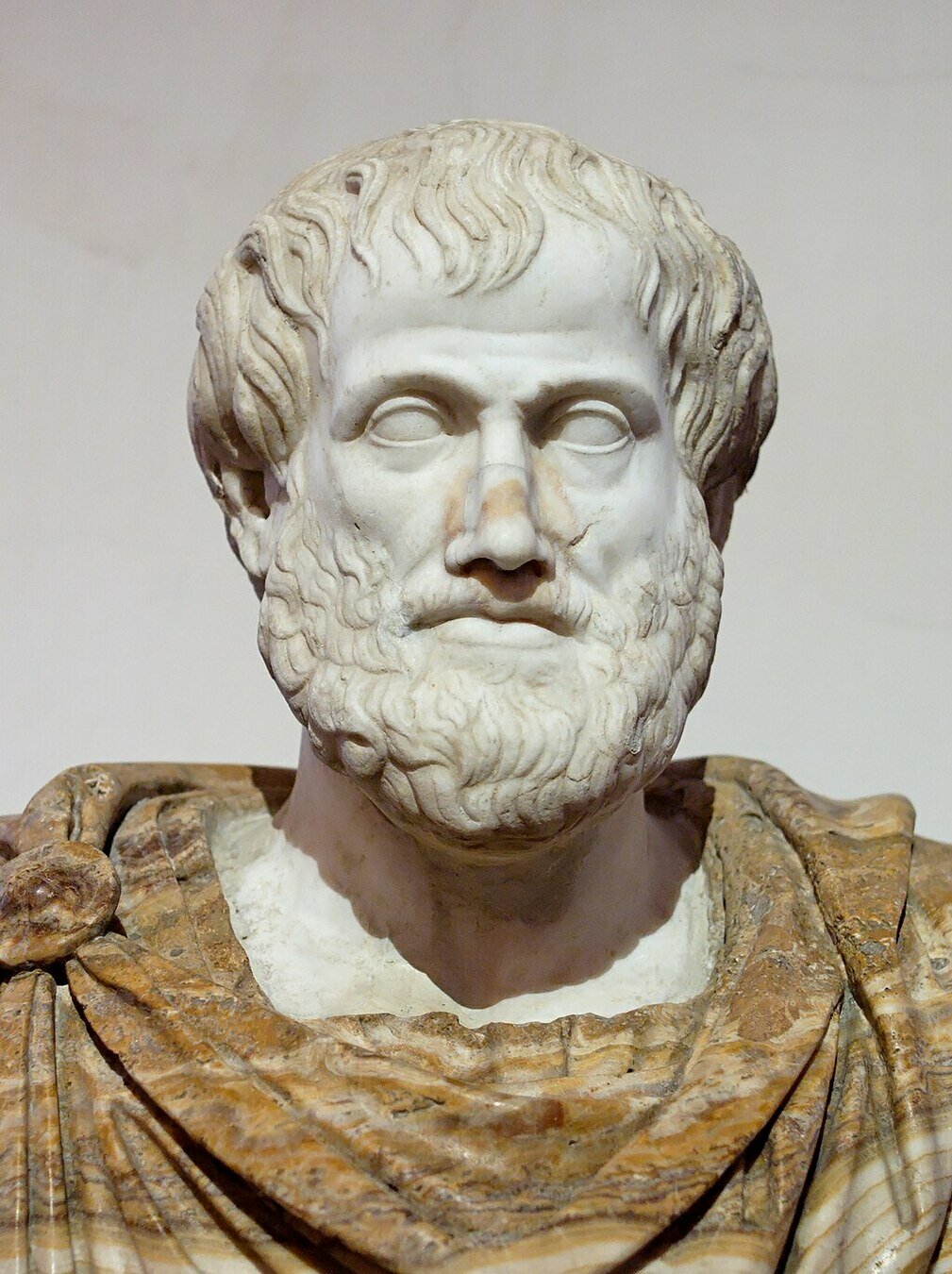
Aristotle
384 – 322 BC
Laid the groundwork for a system of logic based on binary propositions, true and false.
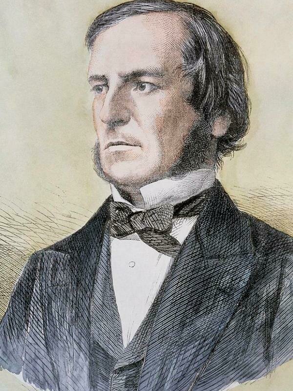
George Boole
1815 – 1864
In 1854 introduced Boolean algebra in his book "An Investigation of the Laws of Thought," which presented a symbolic representation of Aristotle’s logic.
Boolean Operations
While elementary algebra deals with numerical operations, Boolean algebra deals with logical operations. These operations form the backbone of programming logic and the design of digital circuits.
Primary operations
- A & B represents an AND operation
- A || B represents an OR operation
- !A is a NOT, or inversion operation
Secondary operations
Each of these operations can be represented by grouping the primary operations together:
- Exclusive OR (XOR): (A || B) && !(A & B)
- Implication (if A then B): !A || B
- Equivalence (equality): (A & B) || (!A & !B)
There are no numbers in Boolean algebra, only symbols for true and false values.
- TRUE: 1/ON
- FALSE: 0/OFF
Truth Tables
To visualize and understand the outcome of these operations, we use Truth tables. These tables enumerate all possible combinations of input truth values and their corresponding output.
AND
| A | B | OUT |
|---|---|---|
| 0 | 0 | 0 |
| 0 | 1 | 0 |
| 1 | 0 | 0 |
| 1 | 1 | 1 |
OR
| A | B | OUT |
|---|---|---|
| 0 | 0 | 0 |
| 0 | 1 | 1 |
| 1 | 0 | 1 |
| 1 | 1 | 1 |
XOR
| A | B | OUT |
|---|---|---|
| 0 | 0 | 0 |
| 0 | 1 | 1 |
| 1 | 0 | 1 |
| 1 | 1 | 0 |
Implication
| A | B | OUT |
|---|---|---|
| 0 | 0 | 1 |
| 0 | 1 | 1 |
| 1 | 0 | 0 |
| 1 | 1 | 1 |
If A then B otherwise true, i.e. a conditional statement.
Equivalence
| A | B | OUT |
|---|---|---|
| 0 | 0 | 1 |
| 0 | 1 | 0 |
| 1 | 0 | 0 |
| 1 | 1 | 1 |
Boolean Arithmetic
- Boolean operations can be used to perform arithmetic.
- In Boolean arithmetic, results are always either true (1) or false (0).
An OR operation represents addition:
1 + 1 = 1
1 + 0 = 1
0 + 0 = 0
0 + 1 = 1
An AND operation represents multiplication:
1 * 1 = 1
1 * 0 = 0
0 * 0 = 0
0 * 1 = 0
Subtraction and division do not exist in Boolean algebra.
Boolean operations serve as the building blocks for logical circuits that process and compute information in our digital devices.
Part 3: Logical Circuits
Claude Shannon
1916 – 2001
Often regarded as one of the most influential yet overlooked figures in computer science, Claude Shannon laid the foundation for the Information Age with his groundbreaking work in Information Theory.


Every single concept from Boole’s algebra had its physical counterpart in an electric circuit. An on switch could stand for "true" and an off switch for "false," and the whole thing could be represented in 1’s and 0’s. More important, as Shannon pointed out, the logical operators of Boole’s system—AND, OR, NOT—could be replicated exactly as circuits.
By merging principles of Boolean algebra and binary representation with electronic circuits, Shannon forged a path that revolutionized computing.
Computing Machines
Mechanical Computers
These early devices used proportional differences between gears to perform calculations. They were limited to specific tasks and lacked the versatility of general-purpose computations.
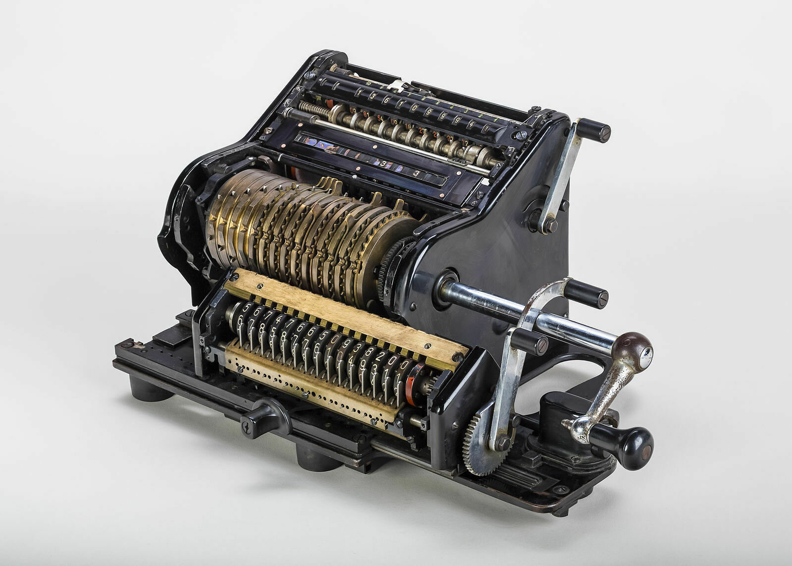
Mechanical calculator
Digital Computers
Digital computers perform calculations using electronic switches to implement logical circuits.
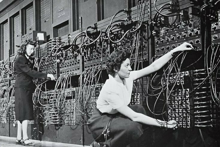
ENIAC programmers
Switches
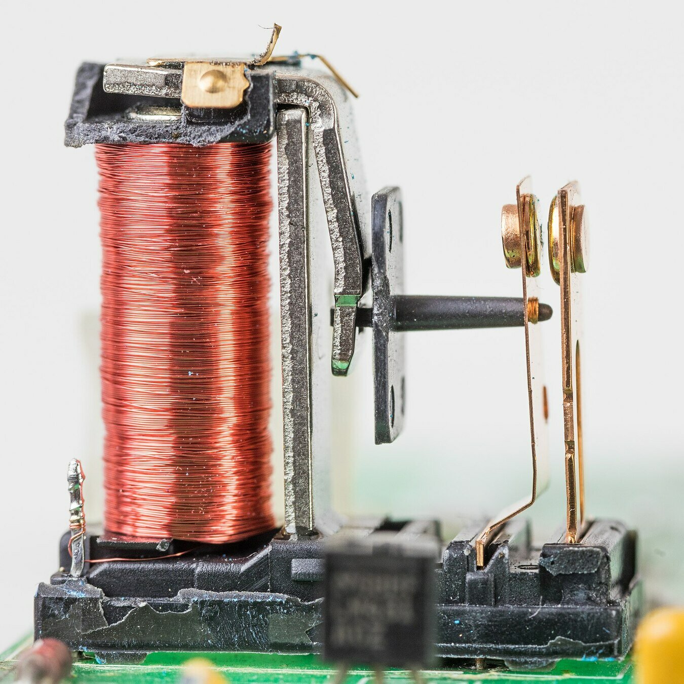
The types of switches used to perform boolean operations in digital computers changed as technology developed.

Relay
Vacuum tube
Transistor
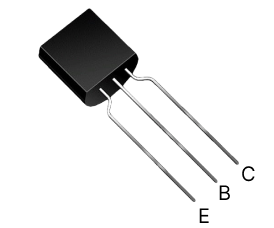

Logic Gates
Transitors can be combined in certain ways to create logic gates. These gates execute basic logical functions that are crucial in performing complex computational tasks. The most common logic gates include:
-
NOT Gate: Flips the input (1 becomes 0 and vice versa).
-
AND Gate: Outputs 1 only when both inputs are 1.
-
OR Gate: Outputs 1 if any input is 1.
-
XOR Gate: Outputs 1 if only one input is 1.
AND gate

OR gate

Logic Circuits
By chaining together different logic gates, we can create logic circuits. These circuits can perform more complex operations and calculations.
Performing binary arithmetic using boolean logic:
In binary, 2 bits are required to represent the number 2. The extra bit is "carried" to the left. The rightmost bit is reset to 0 because of the carry.
| A | B | A+B |
|---|---|---|
| 0 | 0 | 00 |
| 0 | 1 | 01 |
| 1 | 0 | 01 |
| 1 | 1 | 10 |
| A | B | AND | XOR |
|---|---|---|---|
| 0 | 0 | 0 | 0 |
| 0 | 1 | 0 | 1 |
| 1 | 0 | 0 | 1 |
| 1 | 1 | 1 | 0 |
Notice the leftmost bit represents the result of an AND operation. The rightmost bit is the result of an XOR operation.
The Half Adder
Adds two single binary digits and returns a sum plus a carry value.

1
1
0
1
(carry)
(sum)
The Full Adder
A full adder is a combination of two half-adders with an additional OR gate to manage the carry bit.

1
0
1
0
1
(carry)
1
0
(carry)
(sum)
1
0
Move from right to left and carry a 1 if we add two 1s together.
27 + 15
| A | 1 | 1 | 0 | 1 | 1 | (27) |
| B | 0 | 1 | 1 | 1 | 1 | (15) |
1
42
0
1
1
1
1
0
1
1
0
1
Full-adders can be chained together to add large numbers
| FA | FA | FA | FA | FA | FA | ||
|---|---|---|---|---|---|---|---|
| C | 1 | 1 | 1 | 1 | 1 | 0 | |
| A | 0 | 1 | 1 | 0 | 1 | 1 | (27) |
| B | 0 | 0 | 1 | 1 | 1 | 1 | (15) |
| 1 | 0 | 1 | 0 | 1 | 0 | 42 |
Demo: Logic circuits
Bitwise Operations
Bitwise means evaluating a series of bits, on order, from right to left. Bitwise operators apply the operation to each set of digits from right to left.
In Ruby, bitwise operations are represented as:
| AND | & |
| OR | | |
| XOR | ^ |
| NOT | ~ |
| Left shift | << |
| Right shift | >> |
The AND operation 13 & 11 = 9 can be visualized as:
   1 1 0 1 (13)
&  1 0 1 1 (11)
   ———————
   1 0 0 1 (9)
Bit Shifting
Shifting the bits to the left is multiplying by 2. Shifting to the right is dividing by two.
Bitwise left shift:
7 << 2 = 28
000111 << 2 = 011100
Bitwise right shift:
40 >> 2 = 10
0101000 >> 2 = 0001010
The Imposter's Handbook:
The Imposter's Guide to Computer Science
By timrossinfo
The Imposter's Guide to Computer Science
- 443


