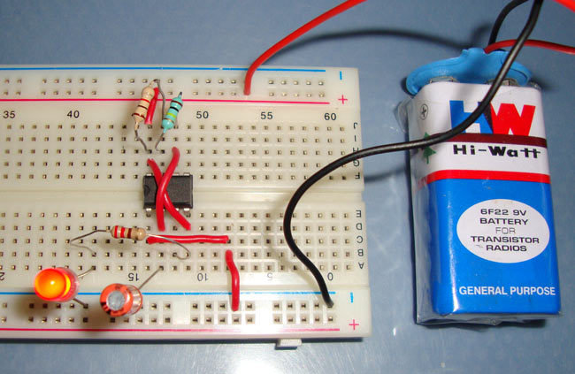
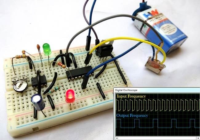
Astable Multivibrator using 555 Timer IC
IC 555
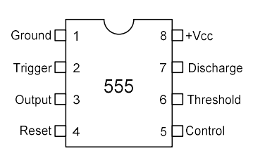
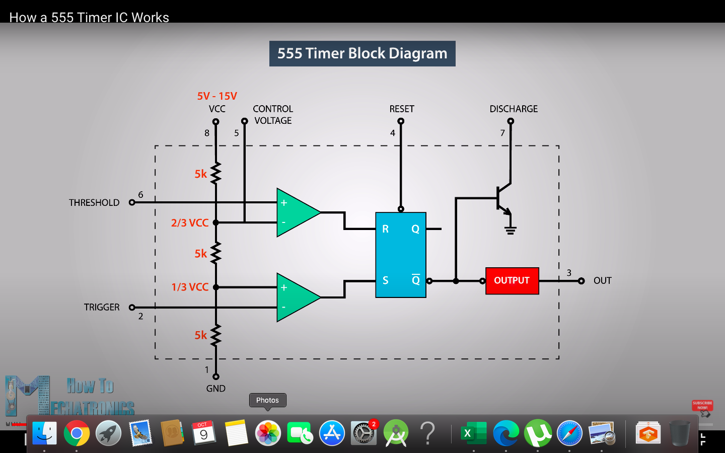
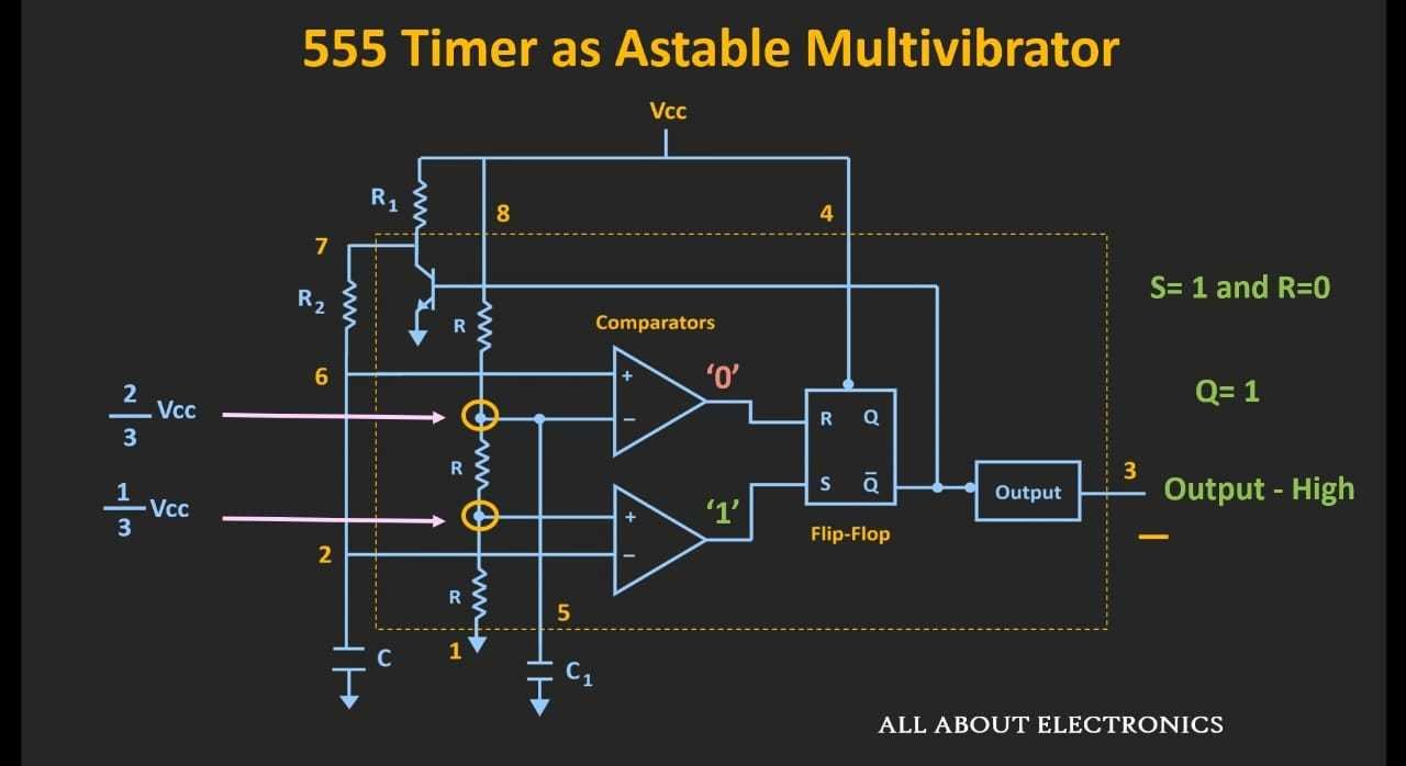
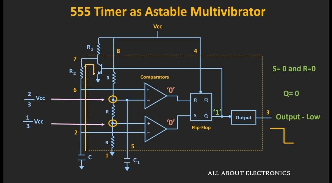
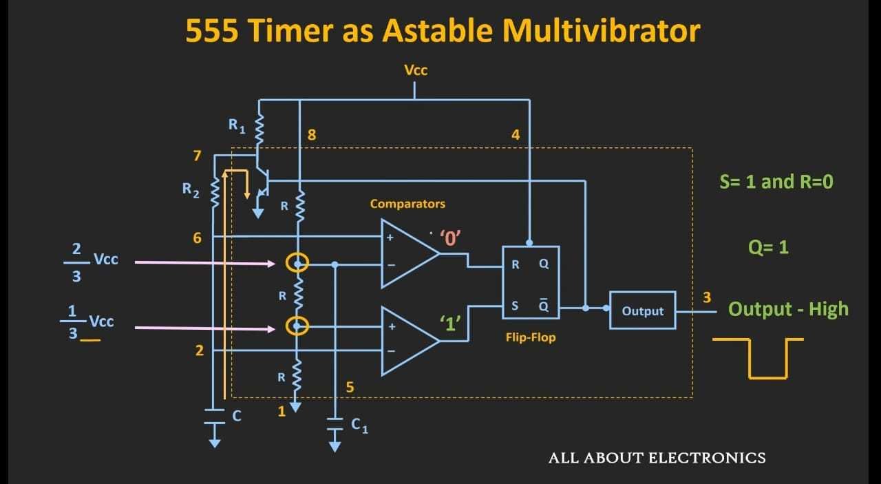
Block Diagram of IC 555
Voltage Divider
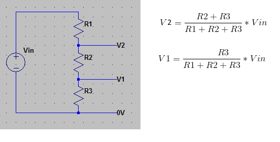
Vcc
(Vcc * 2R)/ 3R
= 2/3 Vcc
(Vcc * 1R)/ 3R
= 1/3 Vcc
By, Voltage Divider Rule, the voltage at the particular points
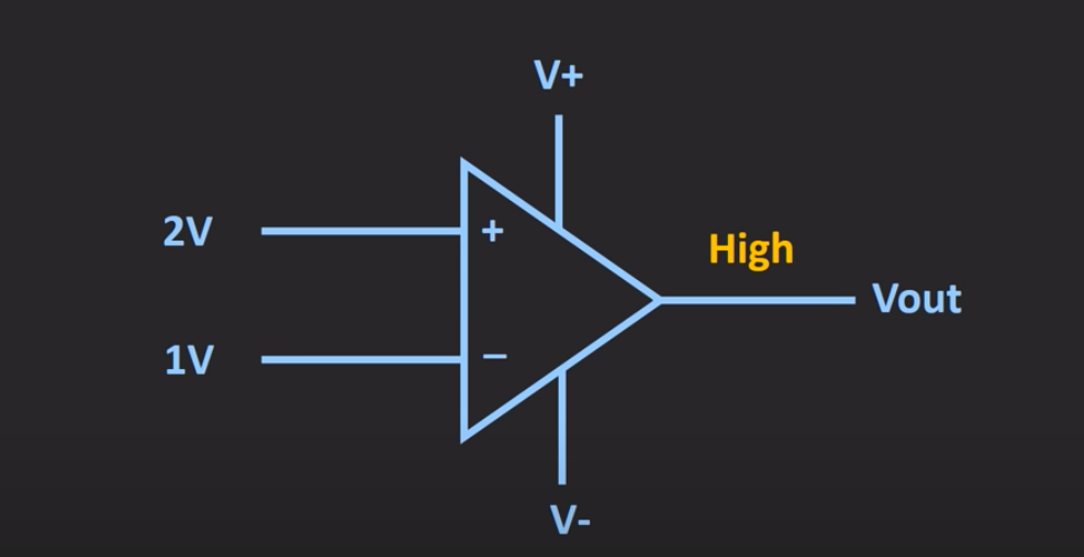
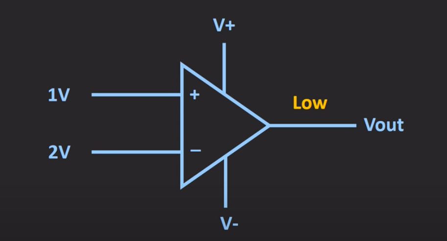
Comparators
S-R Flip Flop & Truth Table

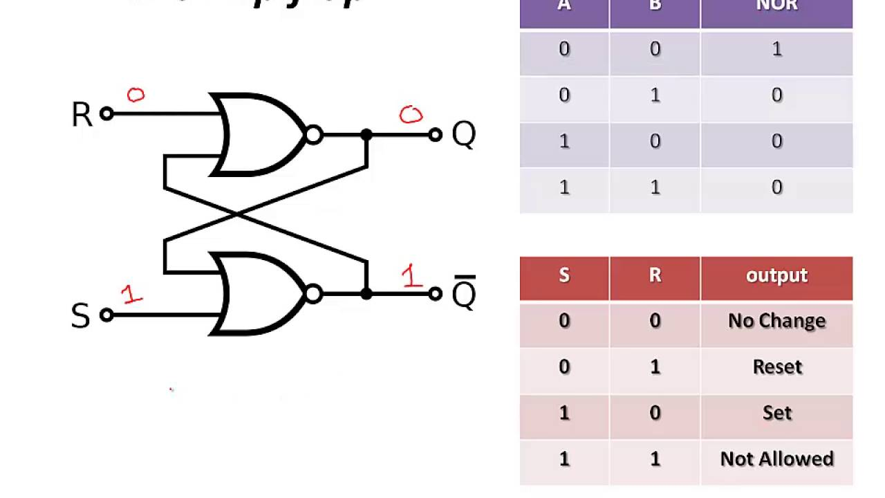
When S = 0 & R =1
1
0
0
1
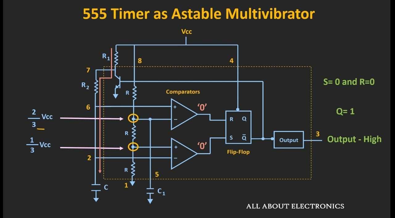
When S = 0 & R =0
0
0
0
1
SR Flipflop


Astable Multivibrator using 555 Timer IC
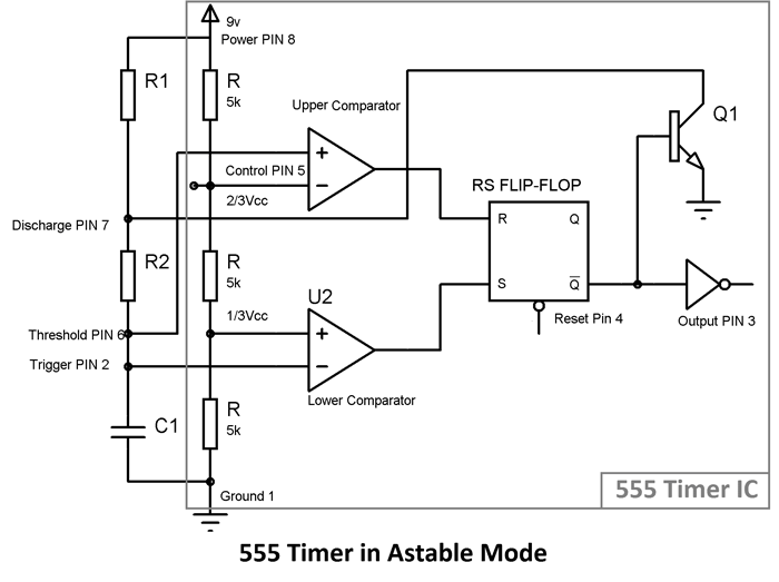
An astable multivibrator has no stable states. Once the Multivibrator is ON, it just changes its states on its own after a certain time period which is determined by the RC time constants. A dc power supply or Vcc is given to the circuit for its operation.
Text
When circuit is just turned 'ON' and the capacitor is fully uncharged
When the capacitor starts charging as current flows though R1 and R2 and the voltage at 2 and 6 is greater than 1/3 Vcc but less than 2/3 Vcc
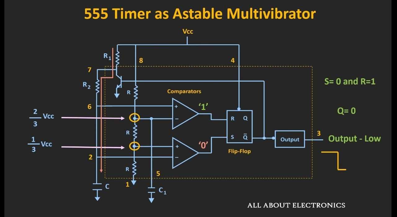
When the voltage across the capacitor becomes just higher than 2/3 Vcc
As Q'=1 The current flows to the Transistor and it goes to the state 'ON' and the capacitor starts discharging through R2 to the transistor. The Voltage across the capacitor goes below 2/3 Vcc
When the capacitor discharges below 1/3 Vcc
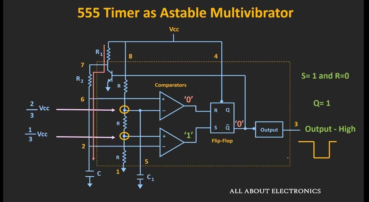
As Q' becomes zero the transistor is set to 'OFF' and the capacitor starts charging again.
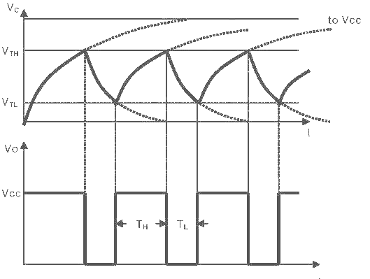
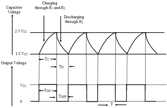
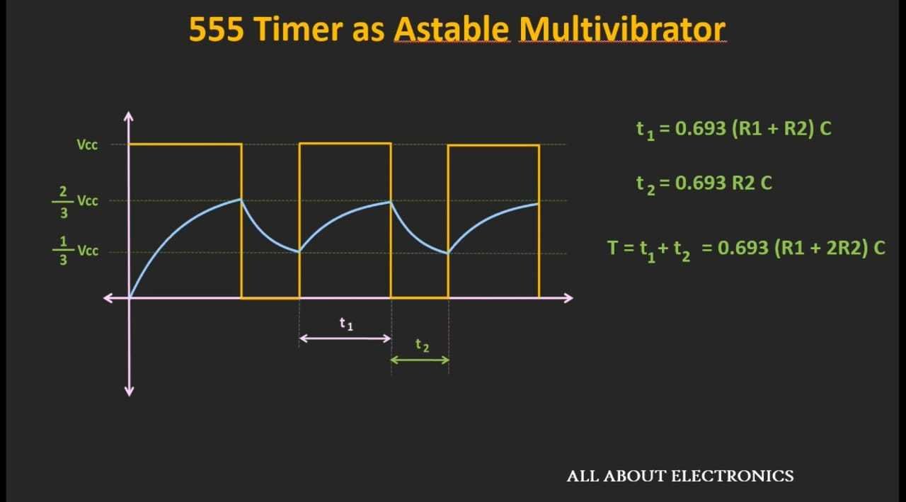
Output Waveform
Derivation
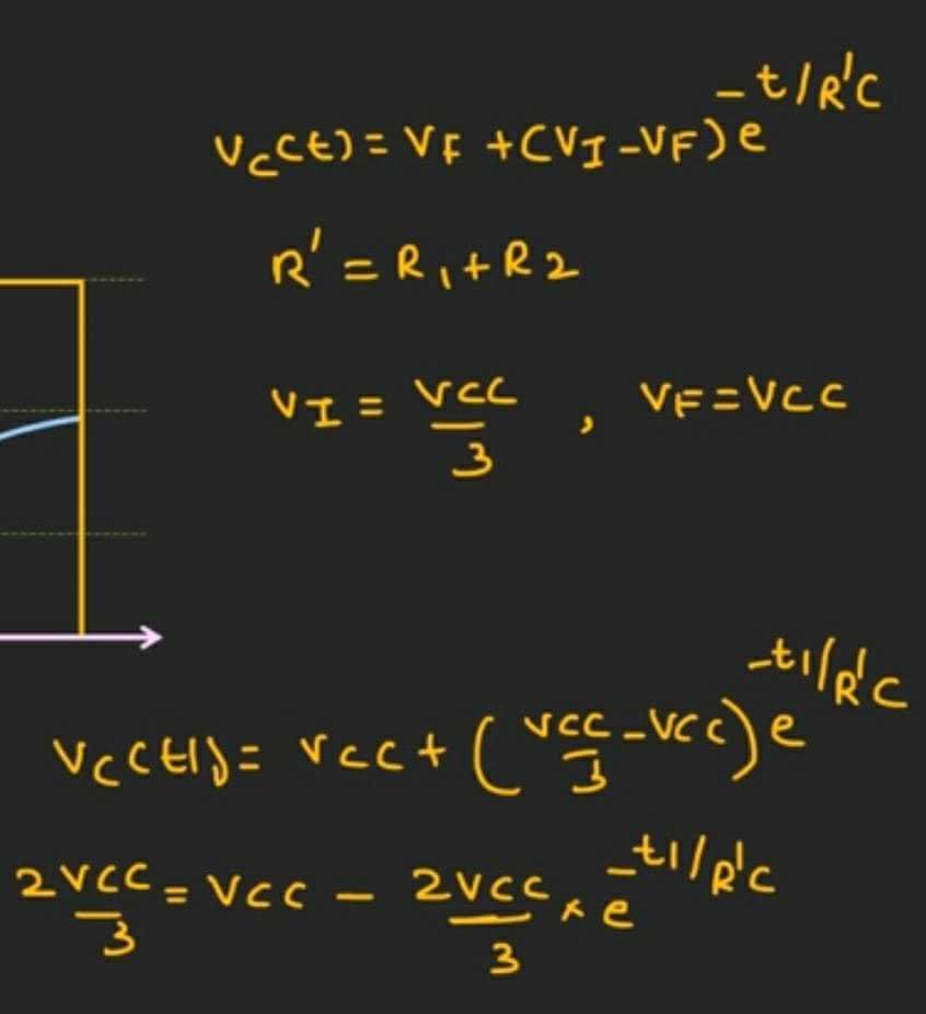
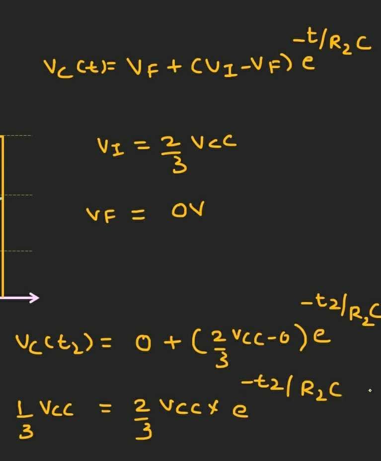
DERIVATION
For finding t1 we check the time it took for the capacitor to charge through R1 and R2 and use the voltage law for the capacitor while charging.

For finding t2 we check the time it took for the capacitor to discharge through R2
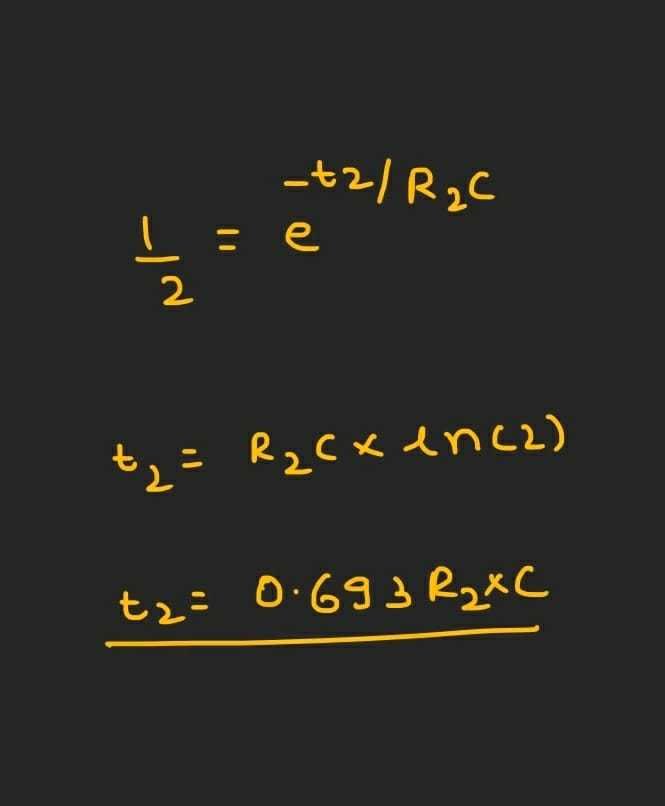
Total time period:
T = t1 + t2
T = 0.693 * (R1 + (2 * R2)) * C
Frequency
f = 1/T = 1/ 0.693 * (R1 + (2 * R2)) * C
f = 1.443/(R1 + (2 * R2)) * C
we find that t1>t2 because during charging the capacitor is charging through R1 and R2 whereas during discharging it only does through R2.
i.e the duty cycle will always be more than 50%.
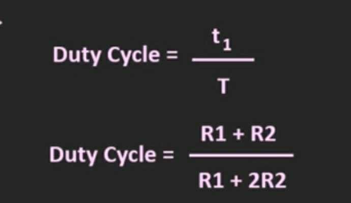
= 'ON' Time
Total Time
Period
If we try to achieve 50% in duty cycle in this circuit we need to keep our R1=0.
But when R1 becomes 0, the collector of the transistor gets exposed to the supply voltage hence can get damaged.
Hence another way to achieve 50% or less is to add a diode across pin 7 and 2.
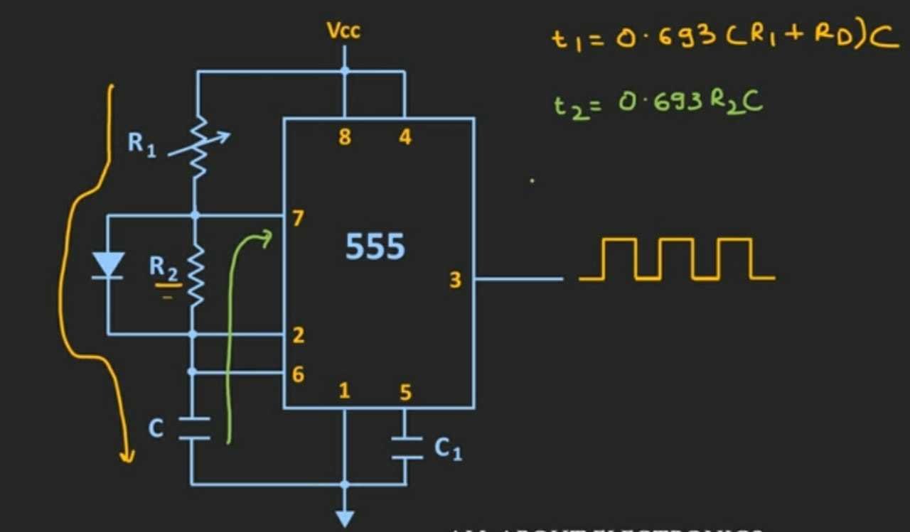
Adjust value of R1
R1+Rd = R2
to achieve 50%
An ideal diode:
Rd=0
R1=R2 D=50%
R1<R2 D<50%
R1>R2 D>50%
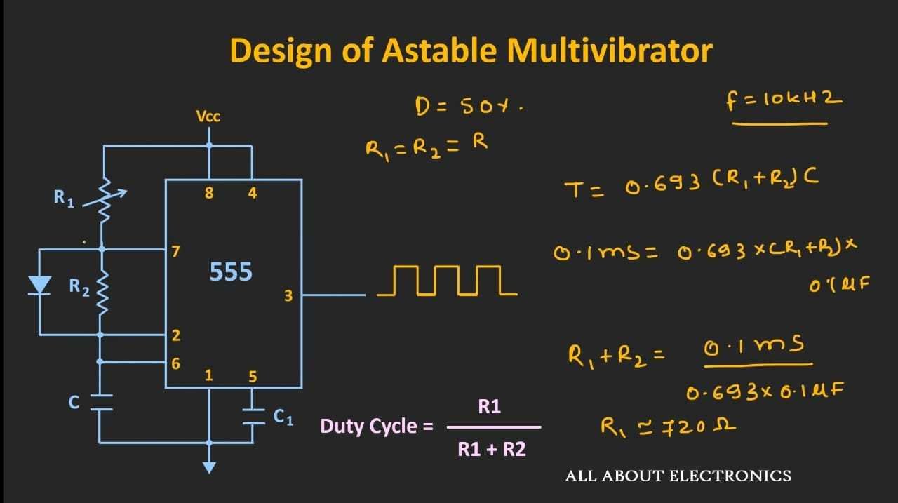
So likewise we can achieve 50% duty cycle from the above circuit by changing the value of R1 using a rheostat.
ADVANTAGES
- No external triggering such as a clock pulse is required
- Simple, inexpensive circuit design
- The circuit can function continuously.
DISADVANTAGES
- Output signal is of low energy
- High energy absorption within the circuit
- Duty cycle less than or equal to 50% can’t be achieved.
- When it is first energized, it is impossible to predict which transistor would go to cut off first due to circuit symmetry.
APPLICATIONS
- One shot or delay timers
- Pulse generation
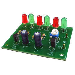
- LED and lamp flashers
- Alarms and tone generation
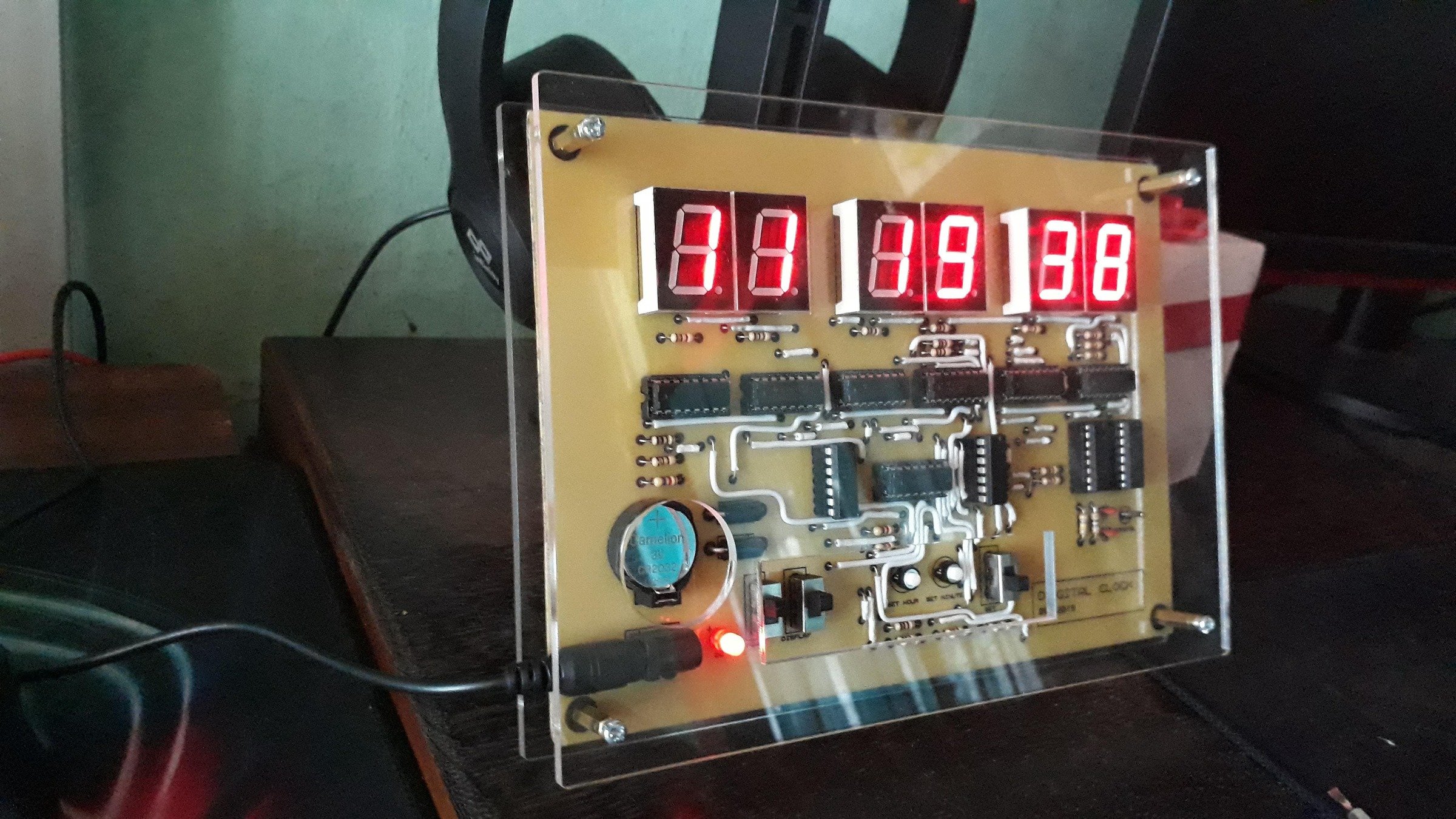
- Logic clocks
- Frequency division
- Power supplies
- Converters


PRECAUTIONS
- All the parameters and circuit were checked
- Make sure all the connections are tight and secure
- Calibrate the oscilloscope accurately.
- Supply voltage is fixed at a point and not more than 15V.
- If R is reduced to zero there is high chance that an extra current will flow through the transistor
Astable Multivibrator using 555 Timer IC
By Amal Augustine


