ECSE 321 - Tutorial 3
Dominic Charley-Roy
https://github.com/dominiccharleyroy
dominic.charley-roy @ mail.mcgill
UML - Use Case Diagrams & Class Diagrams

Use Case Diagrams
The goal of these diagrams is to represent how different types of users interact with the system you are designing.
These are generally very high level and do not include much technical detail. They are a good tool when discussing how the system works with the customer.
Diagram Basics
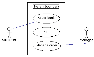
These diagrams show use cases, which is a list of steps to achieve some kind of goal.
Use case diagrams generally have a system boundary, which represents the set of use cases our system is responsible for.
Actors/users are outside the system the boundary and interact with the system via use cases.
Question?
What do use cases which are outside of the system boundary represent? Why might you want these?
They represent use cases which aren't performed by your system. As use case diagrams are shown to the customer, it can help them understand exactly what is included in what you are building.
Use Case Reuse
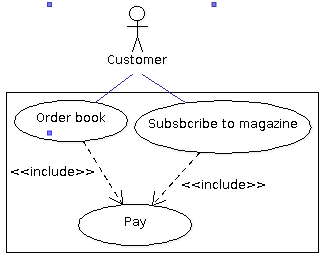
As use cases are list of steps, they can be broken down into use case fragments. These are often shared between larger use cases.
To represent that a small use case is used in a larger use case, we denote an <<include>> relationship.
This shows reuse!
Use Case Extension
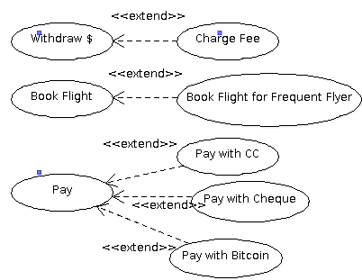
We sometimes want to have a specialized version of a use case, ie. a use case which adds steps to another.
For example, if we were making an ATM we may have a "Withdraw $" use case. But if we are using a card that isn't from the same bank, we want to extend it to be "Withdraw $ and Charge Fee".
We use <<extend>> to denote when a use case adds steps to another.
Note about Actors
Some Use Case diagrams show actor multiplicity, ie. how many of a given actor will our system see.
Suppose we are building an ATM system. We may have 0 or more customers. At least 1 technician will be interacting with the ATM. The bank has 2 to 4 managers responible for the ATM.

Class Diagrams
Class diagrams describe the structure of your system and are a natural fit for object-oriented programs.
Class diagrams show a system's classes, including their attributes and methods, and the relationship between classes.
Some tools let you generate code from class diagrams!
A Basic Class
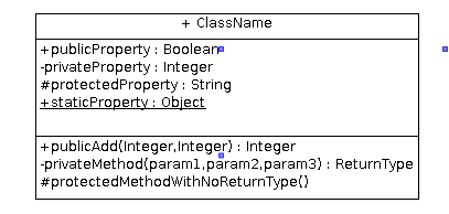
Classes are represented in class diagrams using this notation.
Properties are listed first: visibility propertyname : type
Methods are listed second: visibility methodName(args) : return
Visibility modifiers: + public, - private, # protected, static
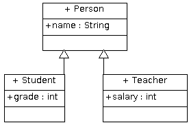
Inheritance
Inheritance is shown in class diagrams using a filled arrow.
Note: Inherited fields are only shown the class where they are defined. In our case, name is defined on Person and so is not shown on Student or Teacher
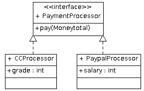
Interfaces
Interfaces are annotated with <<interface>> and only have a method section.
Classes which implement the interface are linked using a dashed full arrow. Again, methods defined on the interface are not repeated.
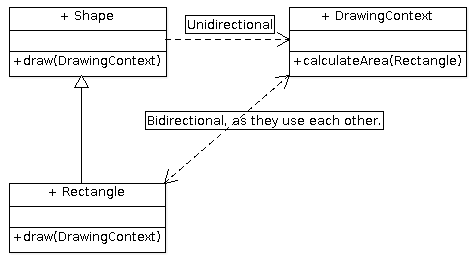
Dependencies
Class A depends on class B if it uses B as a parameter variable or local variable. This is shown with a dashed, open arrow. Can be either unidirectional (A uses B, B does not use A) or bidirectional (A uses B, B uses A).
Note that if A has B as an instance variable, we use associations instead.
Associations / "Has a"
If a class uses another as an instance variable, we mark this as an association, represented via a straight line. We annotate the line with the name of the instance variable. We also put a multiplicity representing how many instances there are.
If a relationship/association has a given name, we can annotate the line. For example a Person subscribes to many Magazines
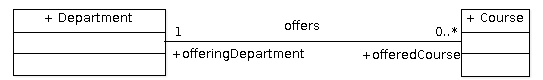
Association Example
A Department offers 0 to many Courses. A Course is offered by exactly 1 Department.
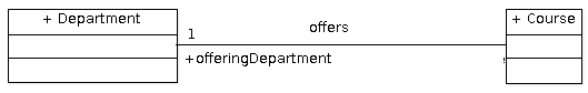
Associations can also be unidirectional. If the Department does not have instance variables for the courses it offers, then we would have this:
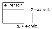
Reflexive Associations
Sometimes a class has an instance variable of the same type. We represent this by making the association line a loop.
Aggregation
This is more specific than "has-a". It is an association that marks a class as part of another object. The most common example is a class A that has a collection of objects of type B. In aggregation, if destroy an object of class A, the aggregated objects of type B are not destroyed. We show aggregation with a hollow diamond.
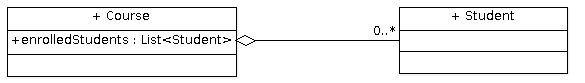
As part of a course, there are many enrolled students. However a Student object does not need to be destroyed if a class is cancelled. The Student can exist without it!
Composition
This is stricter than aggregation. In composition, if we destroy an object of class A, then its parts cannot exist, ie. it does not make sense for them to be an independent object. We represent this using a filled diamond.
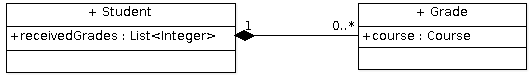
In this example, a Student has a list of grades. However it does not make sense for a Grade object to be independent - whose grade is it?!
Aggregation vs. Composition
Always kind of tricky to differentiate between these two. Given a Container class and a Component class (a Container has many Components).
Aggregation: A Component can be an independent object. Container uses Component.
Composition: A Component needs to be associated with a Container. Container owns Component.

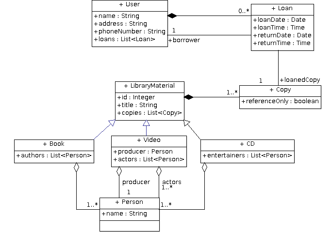
Let's practice!
The library has 1 or more copies of each library item, which can be loaned to users. Reference-only copies are loaned for 2 hours and can't be removed from the library while normal material can be loaned for 2 weeks.
We are designing a backend system for a library. The library has books, videos, and CDs which are loaned. These all have an ID as well as a title. Books have 1+ authors, videos have a producer and 1+ actors, and CDs have 1+ entertainers.
For every loan, the library records the user, the loan date and time and the return date and time. For every user, the library maintains their name, address, and phone number.
ArgoUML Demo

ECSE 321 - Tutorial 3
By dominiccharleyroy