Path Tracing
Parallel Algorithms
David Mayerich
Scalable Tissue Imaging and Modeling (STIM) Laboratory
Department of Electrical and Computer Engineering
Cullen College of Engineering
University of Houston
David Mayerich
STIM Laboratory, University of Houston

Global Illumination
David Mayerich
STIM Laboratory, University of Houston
\(\int \cdots d\theta\)
\(\mathbf{p}\)
\(e=(1,1,1)\)
\(d=(0,0,0)\)
\(\mathbf{v}\)
light from \(\phi\)
emission
from \(\phi\)
\(e=(0,0,0)\)
\(d=(1,1,1)\)
hemisphere
material
collected from \(\theta\)
L(\phi) = E(\phi) + \int_\Omega d(\phi, \theta) C(\theta) d \theta
\(-\frac{\pi}{2}\)
\(\frac{\pi}{2}\)
\(L(\theta)=\)
\(\theta\)
\(\theta=\frac{\pi}{2}\)
\(\theta=-\frac{\pi}{2}\)
Material Properties
David Mayerich
STIM Laboratory, University of Houston
\(\mathbf{p}\)
\(\mathbf{v}\)
\(e=(0,0,1)\)
\(d=(0,0,0)\)
\(e=(0,0,0)\)
\(d=(1,0,0)\)
\(e=(1,1,1)\)
\(d=(0,0,0)\)
\(e=(0,0,0)\)
\(d=(1,1,1)\)
\(e=(0,1,0)\)
\(d=(0,0,1)\)
Rendering Equation
-
\(L\) is the wavelength \(\lambda\) light from direction \(\phi\)
-
\(E\) is the wavelength \(\lambda\) light emitted from the object from direction \(\phi\)
-
\(R\) is the wavelength \(\lambda\) light reflected by the object at from direction \(\phi\)
David Mayerich
STIM Laboratory, University of Houston
L(\phi, \lambda) = E(\phi,\lambda) + R(\phi, \lambda)
R(\phi, \lambda) = \int_\Omega d(\phi, \theta, \lambda) C(\theta, \lambda) d \theta
-
\(d\) defines how the material transmits light \(\lambda\) from direction \(\theta\) to \(\phi\)
-
\(C\) is the light of wavelength \(\lambda\) coming from angle \(\theta\)
L(\phi, \lambda) = E(\phi,\lambda) + \int_\Omega d(\phi, \theta, \lambda) C(\theta, \lambda) d \theta
Bidirectional Reflectance Distribution
-
The material function \(d(\phi, \theta, \lambda)\in\mathbb{R}\) is known as the BRDF
bidirectional reflectance distribution function -
Defines how light is reflected off of a surface
- A BRDF is always positive: \(d(\phi, \theta, \lambda)\geq 0\)
-
Works the same in both directions: \(d(\phi, \theta, \lambda) = d(\theta, \phi, \lambda)\)
-
It doesn't add energy: \(\int_\Omega d(\phi, \theta) \cos(|\theta-\phi|)d\theta \leq 1\)
David Mayerich
STIM Laboratory, University of Houston
L(\phi, \lambda) = E(\phi,\lambda) + \int_\Omega d(\phi, \theta, \lambda) C(\theta, \lambda) d \theta
\(\theta\)
\(\phi\)
\(\mathbf{n}\)
Path Tracing Algorithm
-
calculate a ray \((\mathbf{p}_0, \mathbf{v}_0)\)
-
initialize the ray color \(\mathbf{c}\leftarrow(0, 0, 0)\)
-
initialize the current throughput \(\mathbf{r}=(1,1,1)\) to ensure energy is conserved
-
whilethroughput is high: \(|\mathbf{r}| \geq R_{min}\)- find the closest intersection \(\mathbf{p}_b = \mathbf{p}_{b-1}+t\mathbf{v}_{b-1}\) with object \(s[i]\)
- if you hit the background, set \(\mathbf{r}=(0,0,0)\) which will exit the loop
-
add the emissive light from the object based on throughput: \(\mathbf{c} =\mathbf{c} + \mathbf{r}\circ\mathbf{s}[i]_e\)
-
create a new ray \((\mathbf{p}_b, \mathbf{v}_b)\) with a random direction \(\mathbf{v}_b\) based on the BRDF
-
reduce the throughput based on the BRDF: \(\mathbf{r} = \mathbf{r} \circ \mathbf{d}(\mathbf{v}_{b-1}, \mathbf{v}_{b})\)
- find the closest intersection \(\mathbf{p}_b = \mathbf{p}_{b-1}+t\mathbf{v}_{b-1}\) with object \(s[i]\)
-
assign \(\mathbf{c}\) to the pixel
David Mayerich
STIM Laboratory, University of Houston
Provided Code
-
a tira::Camera class that provides ray directions based on a camera position
David Mayerich
STIM Laboratory, University of Houston
tira::Camera c;
// initialize camera with UI (provided)
glm::vec3 v = c.Ray(-0.2, 0.3)-
an ImGui user interface for controlling the camera position with a GUI
-
a template for two functions that you can expand to create your path tracer
\(-0.5,-0.5\)
\(0.5,0.5\)
\(-0.2,0.3\)
Basic Algorithms
-
some sort of
structorclasscontaining properties of the sphere, at the very least:-
position \(\mathbf{p}\) and radius \(a\)
-
emissive color \(\mathbf{e}=(e_r, e_g, e_b)\)
-
a basic diffuse BRDF color: \(\mathbf{d}=(d_r, d_g, d_b)\)
-
-
code to calculate the intersection of a ray and a sphere
-
a way to generate random numbers so that you can create new random rays after an intersection
-
the path tracing loop described in the previous slide
-
there are great websites describing all of these, but most importantly: You Must Understand Your Own Code!
David Mayerich
STIM Laboratory, University of Houston
Recommended Resources
-
Ray Tracing in One Weekend (Shirley, Black, and Hollasch):
https://raytracing.github.io/books/RayTracingInOneWeekend.html
note: this covers recursive ray tracing, not path tracing
-
Scratchpixel has an online book on 3D rendering:
https://www.scratchapixel.com/
note: you can probably skip to the "Global Illumination and Path Tracing" chapter
-
Intersection tests between objects:
https://www.realtimerendering.com/intersections.html
David Mayerich
STIM Laboratory, University of Houston
Programming Assignment 2
-
Create a scene with at least 10 spheres:
-
3+ spheres must emit light at different wavelengths (colors)
-
Your results will be very noisy in the first pass, so average multiple images
David Mayerich
STIM Laboratory, University of Houston
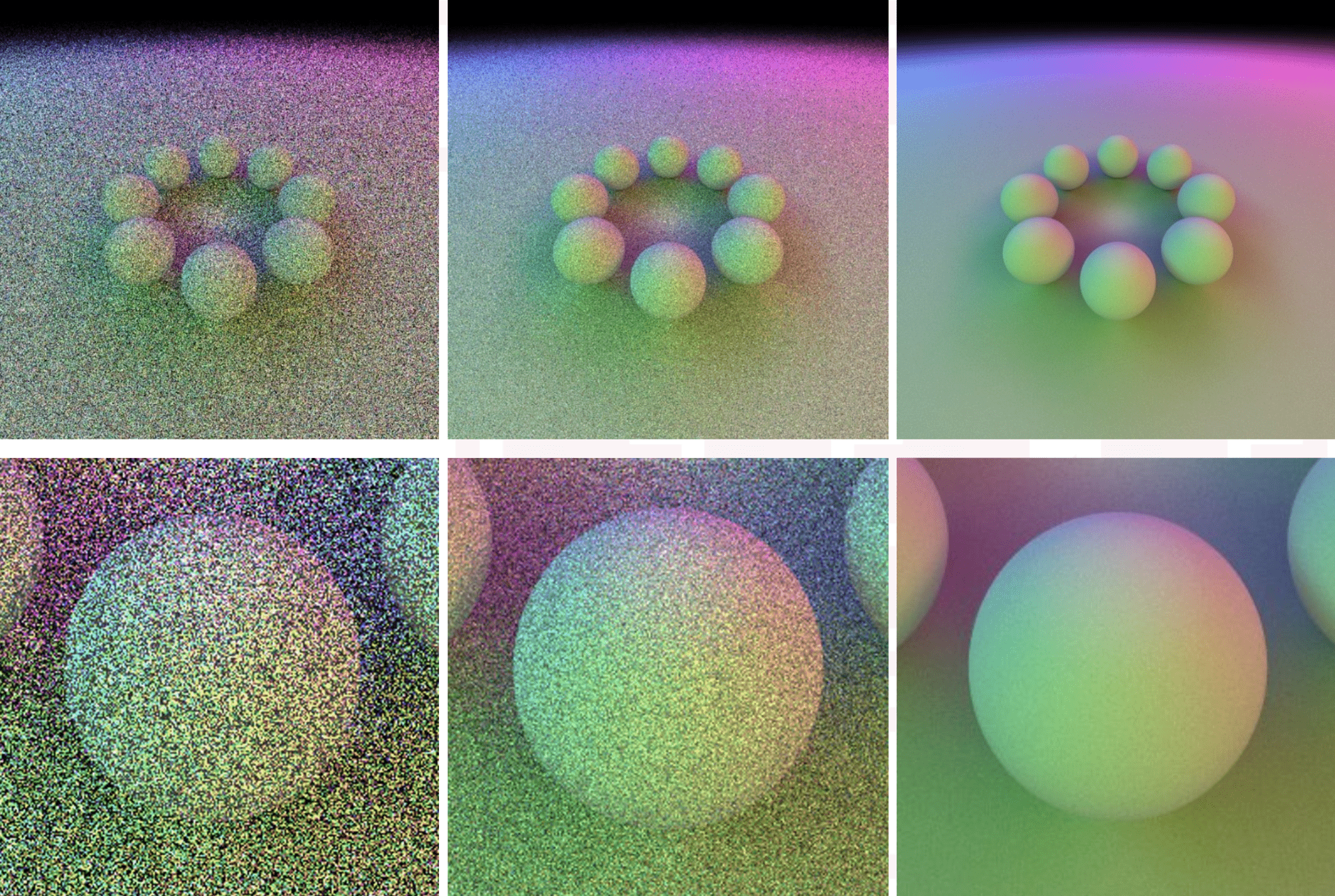
10X
100X
10,000X
-
See the README.md file for implementation details (I'll update it as they come up)
-
Start small (render one purely emissive sphere at the origin
What To Submit:
- a ZIP of your repository: make sure it compiles from scratch with CMake
- include a PDF of your flame graph and a description of your hot path
Template Demo
-
You can pull a repository with a template for the path tracer here:
https://codeberg.org/stimlab/par-raytrace
David Mayerich
STIM Laboratory, University of Houston
C.1a Path Tracing
By STIM Laboratory