ESP32 ADC
Introducing ADC
ADC stands for Analog-to-Digital Converter. It is a system that converts analog signals, such as sound recorded by a microphone or light captured by a digital camera, into digital signals. It can also measure temperature and humidity.
Why is ADC important?
In the digital world of computers and microcontrollers, it's essential to convert real-world, analog signals into digital data that can be processed, analyzed, or stored.
Analog🆚Digital

Analog To Digital

Example Code
from machine import ADC, Pin

adc = ADC(Pin(34))  # Create ADC object on ADC pin
adc.atten(ADC.ATTN_11DB)  # Set attenuation for greater range
reading = adc.read()  # Read a value in range 0-4095
print(reading)
Understanding the ATTN Parameter
The ATTN parameter in the adc.atten() method sets the attenuation level for the ADC, which essentially determines the maximum voltage range that the ADC can measure.
-
ADC.ATTN_0DB: Range 0 - 1.1V -
ADC.ATTN_2_5DB: Range 0 - 1.5V -
ADC.ATTN_6DB: Range 0 - 2.2V -
ADC.ATTN_11DB: Range 0 - 3.3V (full range)
For most applications with the ESP32, you'll use ADC.ATTN_11DB to get the full range of readings.
Using a Potentiometer with the ESP32
A potentiometer is a variable resistor. By turning its knob, you can vary the resistance, which in turn varies the voltage across it. This changing voltage can be read by the ADC on the ESP32.
wokwi-potentiometer
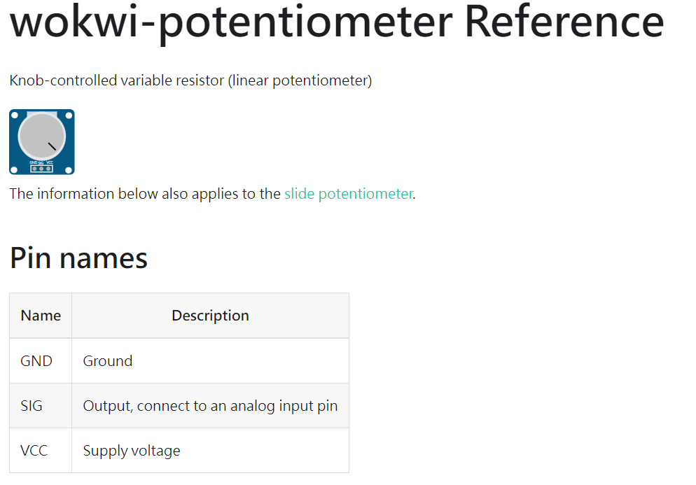
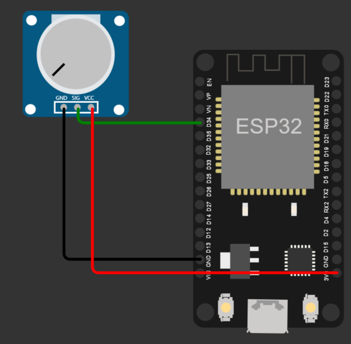
Connection
- Connect the VCC pin of the potentiometer to 3.3V (ESP32).
- Connect the GND pin of the potentiometer to GND.
- Connect the middle pin (SIG) to an ADC pin, such as GPIO34.
MicroPython Code
from machine import ADC, Pin, I2C

# ADC setup
adc = ADC(Pin(34))
adc.atten(ADC.ATTN_11DB)

reading = adc.read()
adc_str = f'Pot Value: {reading}'
print(adc_str)
MicroPython Code
from machine import ADC, Pin, I2C
from utime import sleep

# ADC setup
adc = ADC(Pin(34))
adc.atten(ADC.ATTN_11DB)

while True:
    reading = adc.read()
    adc_str = f'Pot Value: {reading}'
    print(adc_str)
    sleep(0.1)
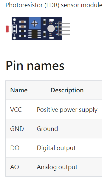
Using a Photo Sensor (LDR)
Photocells, also known as LDRs (Light Dependent Resistors), change resistance based on the amount of light they receive. The brighter the light, the lower the resistance.

Connection
- Connect VCC of the LDR to 3.3V.
- Connect GND of the LDR to GND.
- Connect AO to ADC pin (e.g., GPIO34).
Convert the illumination (in lux)
// These constants should match the photoresistor's "gamma" and "rl10" attributes
const float GAMMA = 0.7;
const float RL10 = 50;

// Convert the analog value into lux value:
int analogValue = analogRead(A0);
float voltage = analogValue / 1024. * 5;
float resistance = 2000 * voltage / (1 - voltage / 5);
float lux = pow(RL10 * 1e3 * pow(10, GAMMA) / resistance, (1 / GAMMA));
# Constants for the photoresistor's attributes
GAMMA = 0.7
RL10 = 50
def calculate_lux(analogValue):
# ESP32 ADC is 12-bit, so max value is 4095 and voltage range is 5V
voltage = analogValue / 4095 * 5
resistance = 2000 * voltage / (1 - voltage / 5)
lux = pow(RL10 * 1e3 * pow(10, GAMMA) / resistance, (1 / GAMMA))
return int(lux)LDR MicroPython Code
from machine import ADC, Pin, I2C
from utime import sleep
import ssd1306
from math import pow

# Constants for the photoresistor's attributes
GAMMA = 0.7
RL10 = 50
def calculate_lux(analogValue):
    voltage = analogValue / 4095 * 5
    resistance = 2000.0 * voltage / (1 - voltage / 5)
    lux = pow(RL10 * 1e3 * pow(10, GAMMA) / resistance, (1 / GAMMA))
    return int(lux)

# ADC setup
adc = ADC(Pin(34))
adc.atten(ADC.ATTN_11DB)

# OLED setup
i2c = I2C(0, scl=Pin(22), sda=Pin(21))
oled_width = 128
oled_height = 64
oled = ssd1306.SSD1306_I2C(oled_width, oled_height, i2c)

while True:
    reading = adc.read()
    lux = calculate_lux(reading)
    # Clear display
    oled.fill(0)
    adc_str = f'Pot Value: {lux:5}'
    oled.text(adc_str, 0, 0)
    oled.show()
sleep(0.1)ESP32 KIT LDR MicroPython Code
from machine import ADC, Pin, I2C
from utime import sleep
import ssd1306
from math import pow

# ADC setup
adc = ADC(Pin(39))
adc.atten(ADC.ATTN_11DB)
# ESP32 Pin assignment
i2c = I2C(0, scl=Pin(22), sda=Pin(21))

oled_width = 128
oled_height = 64
oled = ssd1306.SSD1306_I2C(oled_width, oled_height, i2c)

while True:
    reading = adc.read()
    # Clear display
    oled.fill(0)
    adc_str = f'Pot Value: {reading}'
    oled.text(adc_str, 0, 0)
    oled.show()
    print(adc_str)
    sleep(0.1)
Joystick
- A beginner's guide to using an Analog Joystick with ESP32
- Exploring joystick operation
- Demonstrations in the Worwi simulator
Joystick: Overview
- A device that provides analog input for both vertical and horizontal axes
- Contains an integrated push button
- Utilizes varying voltage levels to determine position
Pin Configuration
| Pin Name | Description |
|---|---|
| VCC | Positive power supply |
| VERT | Vertical axis output (analog) |
| HORZ | Horizontal axis output (analog) |
| SEL | Push button |
| GND | Ground |
Understanding the Joystick Operation
- Idle position:
- VCC/2 voltage on both VERT and HORZ pins
- Vertical Movement:
- Bottom: 0 volts ( 0 )
- Top: VCC volts ( 4095 )
- Horizontal Movement:
- Right: 0 volts ( 0 )
- Left : VCC volts ( 4095 )
The Integrated Push Button
- SEL pin is normally open (floating)
- Clicking on the joystick's center shorts SEL to ground
- Note: The joystick button simulates bouncing by default. Disable bouncing by setting the "bounce" attribute to "0".
Connecting the Joystick to the ESP32
- VCC → 3.3V on ESP32
- VERT → Any analog pin (e.g., GPIO 4)
- HORZ → Any analog pin (e.g., GPIO 2)
- SEL → Any digital pin with pull-up capability (e.g., GPIO 15)
- GND → GND on ESP32
MicroPython Code for Joystick Interface
from machine import ADC, Pin

# Initialize analog pins for horizontal and vertical axes
vert = ADC(Pin(4))
horz = ADC(Pin(2))

vert.atten(ADC.ATTN_11DB)
horz.atten(ADC.ATTN_11DB)

# Initialize SEL pin for the push button
button = Pin(15, Pin.IN, Pin.PULL_UP)

def read_joystick():
    vertical_val = vert.read()
    horizontal_val = horz.read()
    button_status = not button.value()  # Button pressed when value is 0

    return vertical_val, horizontal_val, button_status

while True:
    v, h, b = read_joystick()
    print("Vertical:", v, "Horizontal:", h, "Button Pressed:", b)
    time.sleep(0.5)
Add ESP32 pin numbers and adjust timing as needed.
Applications of Analog Joystick with ESP32
- Gaming and entertainment
- Robotics and drone control
- User interfaces for various applications
Conclusion
- The Analog Joystick provides a versatile input method for various applications
- ESP32 and MicroPython make interfacing and reading the joystick intuitive
- Explore further by integrating the joystick into your projects and see its capabilities in action!
ADC Application
ADC is used as a PWM width value to control devices such as buzzers, LED brightness, and servo motor rotation angles.
ESP32 ADC
By wschen


